Page 4329 of 4731
RAX-6
WHEEL HUB
Revision: 2005 July 2005 FX
10. Loosen fixing bolts and nuts of front lower link, radius rod, and rear lower link in side of suspension mem-
ber.
11. Set jack under rear lower link. Then remove fixing bolt in front lower link side of shock absorber with power tool.
12. Remove bolt and nut in axle side of rear lower link with power tool. Then remove coil spring. Refer to RSU-15, "
REAR LOWER LINK & COIL SPRING" .
13. Remove fixing bolts and nuts in axle side of front lower link, radius rod with power tool.
14. Remove suspension arm and cotter pin at axle, then loosen mounting nut.
15. Use a ball joint remover (suitable tool) to remove suspension arm from axle. Be careful not to damage ball joint boot.
CAUTION:
Tighten temporarily mounting nut to prevent damage to threads and to prevent ball joint remover
(suitable tool) from coming off.
16. Remove axle from vehicle.
INSPECTION AFTER REMOVAL
Ball Joint Inspection
Check for boot breakage, axial looseness, and torque of suspension arm ball joint. Refer to RSU-11,
"INSPECTION AFTER REMOVAL" .
INSTALLATION
�Refer to RAX-5, "Removal and Installation" for tightening torque. Install in the reverse order of removal.
NOTE:
Refer to component parts location and do not reuse non-reusable parts.
�Perform final tightening of installation position of suspension links (rubber bushing) under unladen condi-
tions with tires on level ground, Check wheel alignment. Refer to RSU-5, "
Wheel Alignment Inspection" .
�After adjusting wheel alignment, adjust neutral position of steering angle sensor. Refer to BRC-6, "Adjust-
ment of Steering Angle Sensor Neutral Position" .
Disassembly and AssemblyADS000C6
DISASSEMBLY
Wheel Bearing
CAUTION:
Do not disassemble if wheel bearing has no trouble.
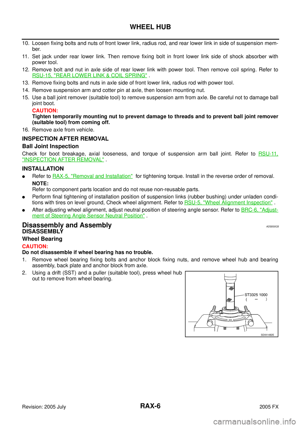
1. Remove wheel bearing fixing bolts and anchor block fixing nuts, and remove wheel hub and bearing assembly, back plate and anchor block from axle.
2. Using a drift (SST) and a puller (suitable tool), press wheel hub out to remove from wheel bearing.
SDIA1482E
Page 4332 of 4731
REAR DRIVE SHAFT RAX-9
C E F
G H
I
J
K L
M A
B
RAX
Revision: 2005 July 2005 FX
REAR DRIVE SHAFTPFP:39600
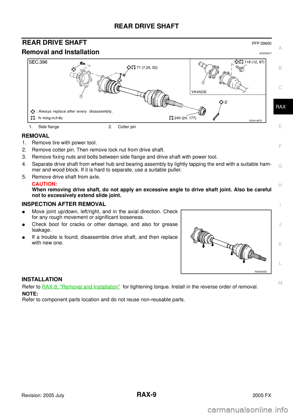
Removal and InstallationADS000C7
REMOVAL
1. Remove tire with power tool.
2. Remove cotter pin. Then remove lock nut from drive shaft.
3. Remove fixing nuts and bolts between side flange and drive shaft with power tool.
4. Separate drive shaft from wheel hub and bearing assembly by lightly tapping the end with a suitable ham- mer and wood block. If it is hard to separate, use a suitable puller.
5. Remove drive shaft from axle. CAUTION:
When removing drive shaft, do not apply an excessive angle to drive shaft joint. Also be careful
not to excessively extend slide joint.
INSPECTION AFTER REMOVAL
�Move joint up/down, left/right, and in the axial direction. Check
for any rough movement or significant looseness.
�Check boot for cracks or other damage, and also for grease
leakage.
�If a trouble is found, disassemble drive shaft, and then replace
with new one.
INSTALLATION
Refer to RAX-9, "Removal and Installation" for tightening torque. Install in the reverse order of removal.
NOTE:
Refer to component parts location and do not reuse non-reusable parts.
1. Side flange 2. Cotter pin
SDIA1487E
RAA0030D
Page 4413 of 4731
RSU-6
REAR SUSPENSION ASSEMBLY
Revision: 2005 July 2005 FX
TOE-IN
Measure toe-in using following procedure. If out of the specification, inspect and replace any damaged or worn
rear suspension parts.
WARNING:
�Always perform the following procedure on a flat surface.
�Make sure that no person is in front of vehicle before push-
ing it.
1. Bounce rear of vehicle up and down to stabilize the posture.
2. Push vehicle straight ahead about 5 m (16 ft).
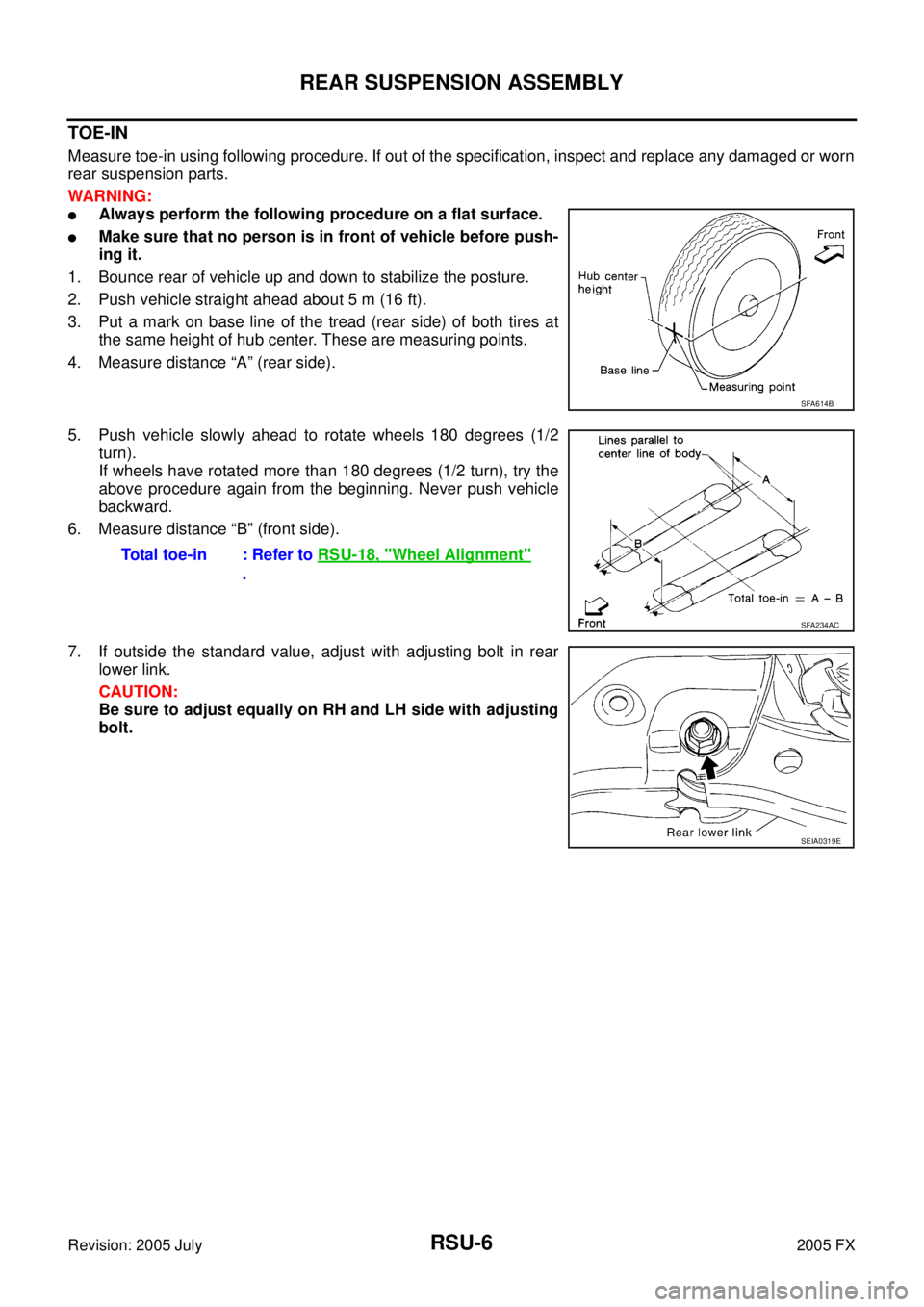
3. Put a mark on base line of the tread (rear side) of both tires at the same height of hub center. These are measuring points.
4. Measure distance “A” (rear side).
5. Push vehicle slowly ahead to rotate wheels 180 degrees (1/2 turn).
If wheels have rotated more than 180 degrees (1/2 turn), try the
above procedure again from the beginning. Never push vehicle
backward.
6. Measure distance “B” (front side).
7. If outside the standard value, adjust with adjusting bolt in rear lower link.
CAUTION:
Be sure to adjust equally on RH and LH side with adjusting
bolt.
SFA614B
Total toe-in : Refer to RSU-18, "Wheel Alignment"
.
SFA234AC
SEIA0319E