Page 4289 of 4731

PS-14
STEERING COLUMN
Revision: 2005 July 2005 FX
INSPECTION AFTER REMOVAL
�Check if there is something wrong with jacket tube of steering column assembly and collar etc. And then if
they are damaged, replace with new one.
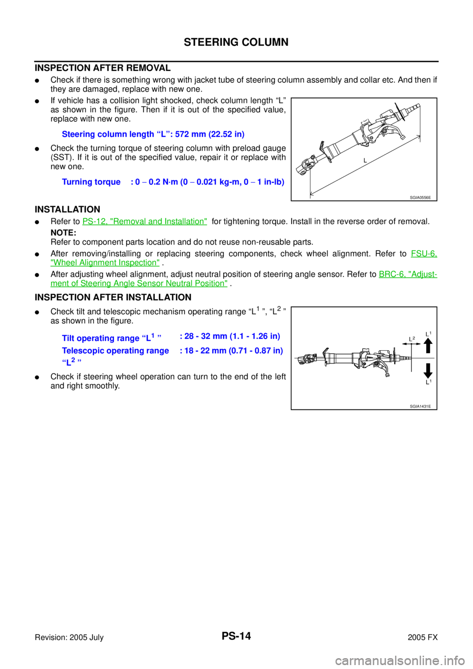
�If vehicle has a collision light shocked, check column length “L”
as shown in the figure. Then if it is out of the specified value,
replace with new one.
�Check the turning torque of steering column with preload gauge
(SST). If it is out of the specified value, repair it or replace with
new one.
INSTALLATION
�Refer to PS-12, "Removal and Installation" for tightening torque. Install in the reverse order of removal.
NOTE:
Refer to component parts location and do not reuse non-reusable parts.
�After removing/installing or replacing steering components, check wheel alignment. Refer to FSU-6,
"Wheel Alignment Inspection" .
�After adjusting wheel alignment, adjust neutral position of steering angle sensor. Refer to BRC-6, "Adjust-
ment of Steering Angle Sensor Neutral Position" .
INSPECTION AFTER INSTALLATION
�Check tilt and telescopic mechanism operating range “L1 ”, “L2 ”
as shown in the figure.
�Check if steering wheel operation can turn to the end of the left
and right smoothly. Steering column length “L”: 572 mm (22.52 in)
Turning torque : 0 − 0.2 N·m (0 − 0.021 kg-m, 0 − 1 in-lb)
SGIA0556E
Tilt operating range “L1 ” : 28 - 32 mm (1.1 - 1.26 in)
Telescopic operating range
“L
2 ” : 18 - 22 mm (0.71 - 0.87 in)
SGIA1431E
Page 4294 of 4731

POWER STEERING GEAR AND LINKAGE PS-19
C
D E
F
H I
J
K L
M A
B
PS
Revision: 2005 July 2005 FX
POWER STEERING GEAR AND LINKAGEPFP:49001
Removal and InstallationAGS000H0
CAUTION:
Spiral cable may snap due to steering operation if steering column is separated from steering gear
assembly. Therefore fix steering wheel with a string to avoid turns.
REMOVAL
1. Set wheels in the straight-ahead position.
2. Remove tires from vehicle with power tool.
3. Remove undercover with power tool.
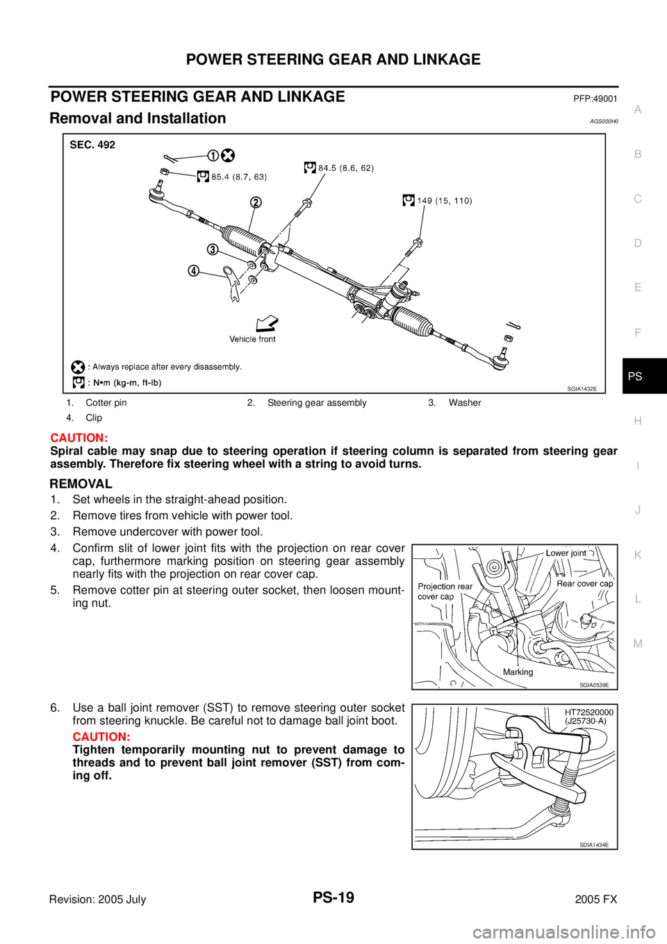
4. Confirm slit of lower joint fits with the projection on rear cover cap, furthermore marking position on steering gear assembly
nearly fits with the projection on rear cover cap.
5. Remove cotter pin at steering outer socket, then loosen mount- ing nut.
6. Use a ball joint remover (SST) to remove steering outer socket from steering knuckle. Be careful not to damage ball joint boot.
CAUTION:
Tighten temporarily mounting nut to prevent damage to
threads and to prevent ball joint remover (SST) from com-
ing off.
1. Cotter pin 2. Steering gear assembly 3. Washer
4. Clip
SGIA1432E
SGIA0539E
SDIA1434E
Page 4321 of 4731

PS-46
SERVICE DATA AND SPECIFICATIONS (SDS)
Revision: 2005 July 2005 FX
SERVICE DATA AND SPECIFICATIONS (SDS)PFP:00030
Steering WheelAGS000H7
Steering AngleAGS000H8
Steering ColumnAGS000H9
Steering Outer Socket and Inner SocketAGS000HA
End play of the axle direction for steering wheel 0 mm (0 in)
Steering wheel play on the outer circumference 0 − 35 mm (0 − 1.38 in)
Inner wheel
Degree minute (Decimal degree) Minimum 32
°00 ′ (32.0 °)
Nominal 35 °00 ′ (35.0 °)
Maximum 36 °00 ′ (36.0 °)
Outer wheel
Degree minute (Decimal degree) Nominal 30
°00 ′ (30.0 °)
Steering column length “ L1 ” 572 mm (22.52 in)
SGIA0556E
Steering gear type PR26AM
Tie-rod ball joint outer socket Swinging torque 0.3
− 2.9 N·m (0.03 − 0.29 kg-m, 3 − 25 in-lb)
Measurement on spring balance
�Measuring point: cotter pin hole of stud 4.84
− 46.7 N (0.5 − 4.8 kg, 1.0 − 10 lb)
Rotating torque 0.3 − 2.9 N·m (0.03 − 0.29 kg-m, 3 − 25 in-lb)
Axial end play 0.5 mm (0.02 in) or less
Tie-rod ball joint inner socket Swinging torque 1.0
− 7.8 N·m (0.11 − 0.79 kg-m, 9 − 69 in-lb)
Measurement on spring balance
�Measuring point: L mark see below,
L=83.2 mm (3.28 in). 12.1
− 93.7 N (1.2 − 9.6 kg, 3.0 − 21 lb)
Axial end play 0.2 mm (0.01 in) or less
SGIA0358E
Page 4586 of 4731

PRECAUTIONS SRS-3
C
D E
F
G
I
J
K L
M A
B
SRS
Revision: 2005 July 2005 FX
PRECAUTIONSPFP:00001
Precautions for Supplemental Restraint System (SRS) “AIR BAG” and “SEAT
BELT PRE-TENSIONER”
AHS000HB
The Supplemental Restraint System such as “AIR BAG” and “SEAT BELT PRE-TENSIONER”, used along
with a front seat belt, helps to reduce the risk or severity of injury to the driver and front passenger for certain
types of collision. This system includes seat belt switch inputs and dual stage front air bag modules. The SRS
system uses the seat belt switches to determine the front air bag deployment, and may only deploy one front
air bag, depending on the severity of a collision and whether the front occupants are belted or unbelted.
Information necessary to service the system safely is included in the SRS and SB section of this Service Man-
ual.
WARNING:
�To avoid rendering the SRS inoperative, which could increase the risk of personal injury or death
in the event of a collision which would result in air bag inflation, all maintenance must be per-
formed by an authorized NISSAN/INFINITI dealer.
�Improper maintenance, including incorrect removal and installation of the SRS, can lead to per-
sonal injury caused by unintentional activation of the system. For removal of Spiral Cable and Air
Bag Module, see the SRS section.
�Do not use electrical test equipment on any circuit related to the SRS unless instructed to in this
Service Manual. SRS wiring harnesses can be identified by yellow and/or orange harnesses or
harness connectors.
Precautions for SRS “AIR BAG” and “SEAT BELT PRE-TENSIONER” ServiceAHS000HC
�Do not use electrical test equipment to check SRS circuits unless instructed to in this Service Manual.
�Before servicing the SRS, turn ignition switch OFF, disconnect both battery cables and wait at least 3 min-
utes.
For approximately 3 minutes after the cables are removed, it is still possible for the air bag and seat belt
pre-tensioner to deploy. Therefore, do not work on any SRS connectors or wires until at least 3 minutes
have passed.
�Diagnosis sensor unit must always be installed with their arrow marks “ ⇐” pointing towards the front of the
vehicle for proper operation. Also check diagnosis sensor unit for cracks, deformities or rust before instal-
lation and replace as required.
�The spiral cable must be aligned with the neutral position since its rotations are limited. Do not turn steer-
ing wheel and column after removal of steering gear.
�Handle air bag module carefully. Always place driver and front passenger air bag modules with the pad
side facing upward and seat mounted front side air bag module standing with the stud bolt side facing
down.
�Conduct self-diagnosis to check entire SRS for proper function after replacing any components.
�After air bag inflates, the front instrument panel assembly should be replaced if damaged.
�Always replace instrument panel pad following front passenger air bag deployment.
Page 4620 of 4731

SPIRAL CABLE SRS-37
C
D E
F
G
I
J
K L
M A
B
SRS
Revision: 2005 July 2005 FX
SPIRAL CABLEPFP:25554
Removal and InstallationAHS000HX
REMOVAL
CAUTION:
Before servicing SRS, turn ignition switch OFF, disconnect both battery cables and wait at least 3 min-
utes.
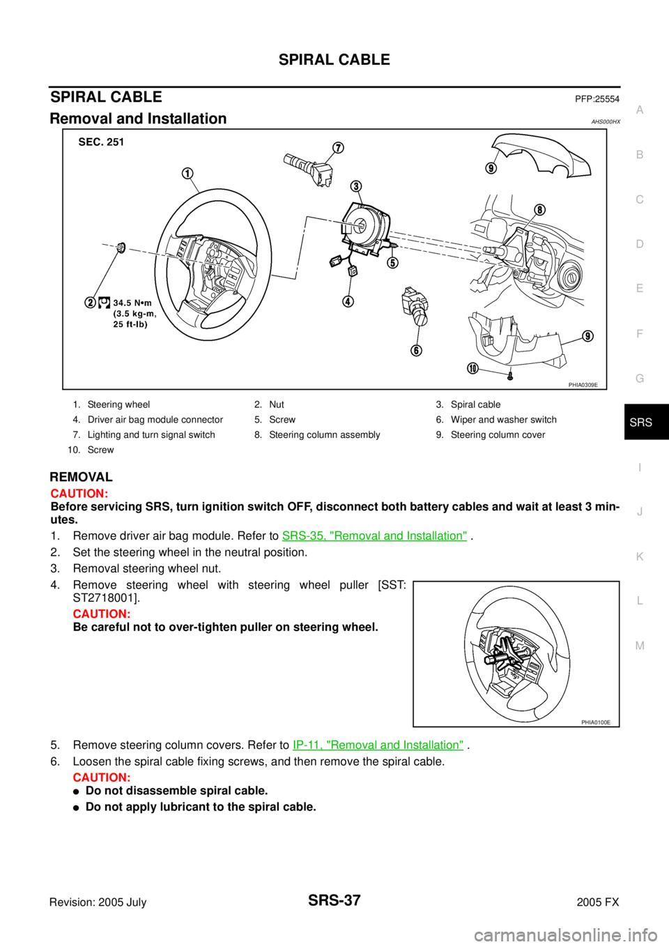
1. Remove driver air bag module. Refer to SRS-35, "
Removal and Installation" .
2. Set the steering wheel in the neutral position.
3. Removal steering wheel nut.
4. Remove steering wheel with steering wheel puller [SST: ST2718001].
CAUTION:
Be careful not to over-tighten puller on steering wheel.
5. Remove steering column covers. Refer to IP-11, "
Removal and Installation" .
6. Loosen the spiral cable fixing screws, and then remove the spiral cable. CAUTION:
�Do not disassemble spiral cable.
�Do not apply lubricant to the spiral cable.
PHIA0309E
1. Steering wheel 2. Nut 3. Spiral cable
4. Driver air bag module connector 5. Screw 6. Wiper and washer switch
7. Lighting and turn signal switch 8. Steering column assembly 9. Steering column cover
10. Screw
PHIA0100E