Page 4612 of 4731
TROUBLE DIAGNOSIS SRS-29
C
D E
F
G
I
J
K L
M A
B
SRS
Revision: 2005 July 2005 FX
Trouble Diagnosis without CONSULT-IIAHS000HT
DIAGNOSTIC PROCEDURE 6
Inspecting SRS Malfunctioning Parts by Using “AIR BAG” Warning Lamp — Diagnosis Mode
NOTE:
SRS will not enter Diagnosis mode if no malfunction is detected in User mode.
1. Turn ignition switch ON.
2. After “AIR BAG” warning lamp lights for 7 seconds, turn ignition switch OFF within 1 second.
3. Wait more than 3 seconds.
4. Repeat the steps 1 to 3 twice. (Perform three times in all.)
5. Turn ignition switch ON.
SRS is now in Diagnosis mode.
“AIR BAG” warning lamp operates in Diagnosis mode as follows:
WARNING LAMP FLASH CODE CHART
PHIA0532E
PHIA1233E
SHIA0028E
Page 4616 of 4731

TROUBLE DIAGNOSIS SRS-33
C
D E
F
G
I
J
K L
M A
B
SRS
Revision: 2005 July 2005 FX
Trouble Diagnosis: “AIR BAG” Warning Lamp Does Not Turn OFFAHS000HU
DIAGNOSTIC PROCEDURE 7
1. CHECK THE DEPLOYMENT OF AIR BAG MODULE
Is air bag module deployed?
YES or NO
YES >> Refer to SRS-46, "COLLISION DIAGNOSIS" .
NO >> GO TO 2.
2. CHECK THE AIR BAG FUSE
Check 10A fuse [No. 13, located in fuse block (J/B)].
Refer to PG-3, "
POWER SUPPLY ROUTING CIRCUIT" .
OK or NG
OK >> GO TO 4.
NG >> GO TO 3.
3. CHECK AIR BAG FUSE AGAIN
Replace “AIR BAG” fuse and turn ignition switch ON.
Does the
“AIR BAG” fuse blow again?
YES >> Repair or replace main harness.
NO >> INSPECTION END
4. CHECK DIAGNOSIS SENSOR UNIT
Connect CONSULT-II and touch “START”.
�Is “AIR BAG” displayed on CONSULT-II?
YES or NO
YES >> GO TO 5.
NO >> Visually check the wiring harness connection of diagno- sis sensor unit. If the harness connection check result is
OK, replace diagnosis sensor unit.
5. CHECK HARNESS CONNECTION
Is harness connection between warning lamp and diagnosis sensor unit OK?
OK or NG
OK >> Replace diagnosis sensor unit.
NG >> Connect “AIR BAG” warning lamp and diagnosis sensor unit connector properly. If “AIR BAG” warning lamp still does not go off, replace harness.
BCIA0030E
Page 4617 of 4731
SRS-34
TROUBLE DIAGNOSIS
Revision: 2005 July 2005 FX
Trouble Diagnosis: “AIR BAG” Warning Lamp Does Not Turn ONAHS000HV
DIAGNOSTIC PROCEDURE 8
1. CHECK METER FUSE
Check 10A fuse [No. 14, located in fuse block (J/B)].
Refer to PG-3, "
POWER SUPPLY ROUTING CIRCUIT" .
OK or NG
OK >> GO TO 3.
NG >> GO TO 2.
2. CHECK METER FUSE AGAIN
Replace 10A fuse [No. 14, located in fuse block (J/B)] and turn ignition switch ON.
Does the meter fuse blow again?
YES >> Repair or replace the related harness.
NO >> INSPECTION END
3. CHECK HARNESS CONNECTION BETWEEN DIAGNOSIS SENSOR UNIT AND COMBINATION
METER
Disconnect diagnosis sensor unit connector and turn ignition switch ON.
�Does “AIR BAG” warning lamp turn on?
YES or NO
YES >> Replace diagnosis sensor unit.
NO >> Replace combination meter assembly.
Page 4618 of 4731
DRIVER AIR BAG MODULE SRS-35
C
D E
F
G
I
J
K L
M A
B
SRS
Revision: 2005 July 2005 FX
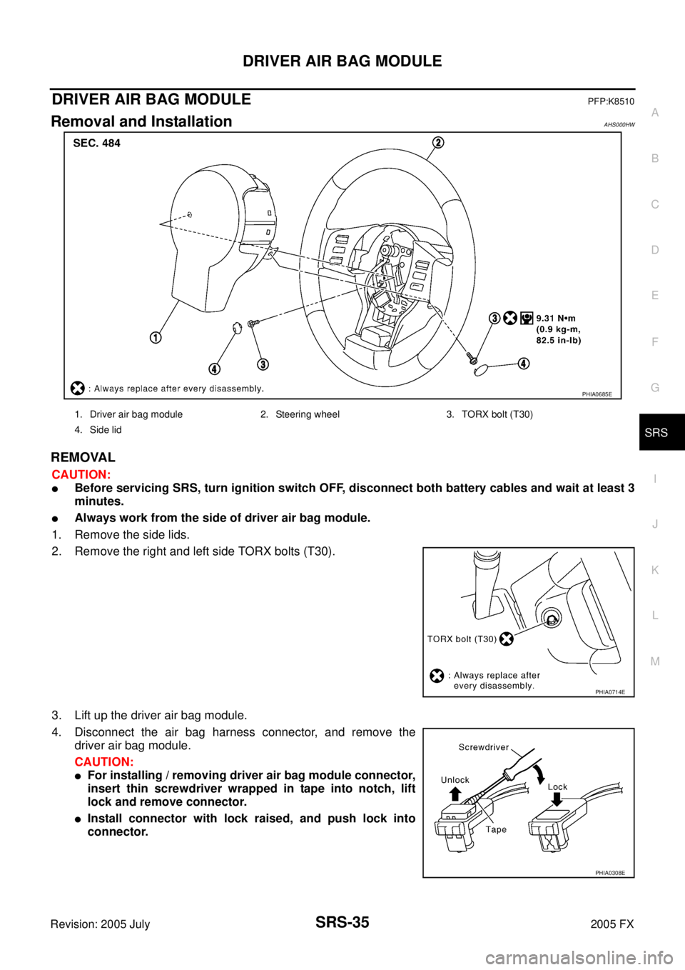
DRIVER AIR BAG MODULEPFP:K8510
Removal and InstallationAHS000HW
REMOVAL
CAUTION:
�Before servicing SRS, turn ignition switch OFF, disconnect both battery cables and wait at least 3
minutes.
�Always work from the side of driver air bag module.
1. Remove the side lids.
2. Remove the right and left side TORX bolts (T30).
3. Lift up the driver air bag module.
4. Disconnect the air bag harness connector, and remove the driver air bag module.
CAUTION:
�For installing / removing driver air bag module connector,
insert thin screwdriver wrapped in tape into notch, lift
lock and remove connector.
�Install connector with lock raised, and push lock into
connector.
PHIA0685E
1. Driver air bag module 2. Steering wheel 3. TORX bolt (T30)
4. Side lid
PHIA0714E
PHIA0308E
Page 4620 of 4731

SPIRAL CABLE SRS-37
C
D E
F
G
I
J
K L
M A
B
SRS
Revision: 2005 July 2005 FX
SPIRAL CABLEPFP:25554
Removal and InstallationAHS000HX
REMOVAL
CAUTION:
Before servicing SRS, turn ignition switch OFF, disconnect both battery cables and wait at least 3 min-
utes.
1. Remove driver air bag module. Refer to SRS-35, "
Removal and Installation" .
2. Set the steering wheel in the neutral position.
3. Removal steering wheel nut.
4. Remove steering wheel with steering wheel puller [SST: ST2718001].
CAUTION:
Be careful not to over-tighten puller on steering wheel.
5. Remove steering column covers. Refer to IP-11, "
Removal and Installation" .
6. Loosen the spiral cable fixing screws, and then remove the spiral cable. CAUTION:
�Do not disassemble spiral cable.
�Do not apply lubricant to the spiral cable.
PHIA0309E
1. Steering wheel 2. Nut 3. Spiral cable
4. Driver air bag module connector 5. Screw 6. Wiper and washer switch
7. Lighting and turn signal switch 8. Steering column assembly 9. Steering column cover
10. Screw
PHIA0100E
Page 4622 of 4731

FRONT PASSENGER AIR BAG MODULE SRS-39
C
D E
F
G
I
J
K L
M A
B
SRS
Revision: 2005 July 2005 FX
FRONT PASSENGER AIR BAG MODULEPFP:K8515
Removal and InstallationAHS000HY
REMOVAL
CAUTION:
�Before servicing SRS, turn ignition switch OFF, disconnect both battery cables and wait at least 3
minutes.
�Always work from the side of or under front passenger air bag module.
1. Remove glove box assembly and instrument passenger lower panel. Refer to IP-13, "
(J) Instrument Pas-
senger Lower Panel" .
2. Remove display control unit, if navigation system is equipped.
3. Remove tire pressure warning control unit, if tire pressure warning control system is equipped.
4. Disconnect front passenger air bag module connector.
5. Remove the front passenger air bag module fixing nuts and bolt, then remove front passenger air bag module.
CAUTION:
�Always place front passenger air bag module with caution
label side facing upward.
�Do not insert any foreign objects (screwdriver, etc.) into
front passenger air bag module.
�Do not disassemble front passenger air bag module.
�Do not use old bolts after removal; replace with new bolts.
�Replace front passenger air bag module if it has been
dropped or sustained an impact.
�Do not expose the front passenger air bag module to tem-
peratures exceeding 90 °C (194 °F).
�Do not allow oil, grease or water to come in contact with the
front passenger air bag module.
�After front passenger air bag module inflates, the instru-
ment panel assembly should be replaced.
INSTALLATION
Install in the reverse order of removal.
CAUTION:
�Always work from the side of or under front passenger air bag module.
�After the work is completed, perform self-diagnosis to make sure no malfunction is detected.
Refer to SRS-17, "
SRS Operation Check" .
PHIA0322E
PHIA0325E
SBF814E
Page 4623 of 4731

SRS-40
SIDE CURTAIN AIR BAG MODULE
Revision: 2005 July 2005 FX
SIDE CURTAIN AIR BAG MODULEPFP:985P0
Removal and InstallationAHS000I0
REMOVAL
CAUTION:
�Before servicing SRS, turn ignition switch OFF, disconnect both battery cables and wait at least 3
minutes.
�Always work from the side of the side curtain air bag module.
1. Remove headlining. Refer to EI-41, "
Removal and Installation" .
2. Disconnect side curtain air bag connector.
3. Remove side curtain air bag module fixing bolts, and remove the side curtain air bag module.
CAUTION:
�Always place the side curtain air bag module with the warn-
ing label facing upward.
�Do not disassemble side curtain air bag module.
�Do not insert any foreign objects (screwdriver, etc.) into air
bag module connector.
�Replace side curtain air bag module if it has been dropped
or sustained an impact.
�Do not expose the air bag module to temperatures exceed-
ing 90 °C (194 °F).
�Do not allow oil, grease or water to come in contact with the
side curtain air bag module.
1. Side curtain air bag Inflator 2. Side curtain air bag 3. Bolt
4. Assist grip bracket 5. Bolt (There is no torque control)
PHIA0656E
PHIA0317E
SBF814E
Page 4625 of 4731
SRS-42
CRASH ZONE SENSOR
Revision: 2005 July 2005 FX
CRASH ZONE SENSORPFP:98531
Removal and InstallationAHS000I1
REMOVAL
CAUTION:
Before servicing SRS, turn ignition switch OFF, disconnect both battery cables and wait at least 3 min-
utes.
1. Remove front grille. Refer to EI-22, "
Removal and Installation" .
2. Remove crash zone sensor connector.
3. Remove crash zone sensor fixing nuts.
CAUTION:
�Replace crash zone sensor if it has been dropped or sustained an impact.
�Do not disassemble crash zone sensor.
INSTALLATION
Install in the reverse order of removal.
CAUTION:
�Check crash zone sensor for proper installation.
�After the work is complete, perform self-diagnosis to make sure that no malfunction is detected.
Refer to SRS-17, "
SRS Operation Check" .
PHIA0316E