Page 4317 of 4731
PS-42
HYDRAULIC LINE
Revision: 2005 July 2005 FX
VQ35DE AWD MODEL
7. Oil cooler 8. Eye bolt 9. Copper washer
10. Oil pressure sensor
SGIA0560E
1. Reservoir tank 2. Reservoir tank bracket 3. Suction hose
4. High pressure hose 5. Oil pump 6. Steering gear assembly
7. Oil cooler 8. Eye bolt 9. Copper washer
10. Oil pressure sensor
Page 4318 of 4731
HYDRAULIC LINE PS-43
C
D E
F
H I
J
K L
M A
B
PS
Revision: 2005 July 2005 FX
Removal and InstallationAGS000H6
�Refer to PS-41, "Components" for tightening torque. Install in the reverse order of removal.
NOTE:
Refer to component parts location and do not reuse non-reusable parts.
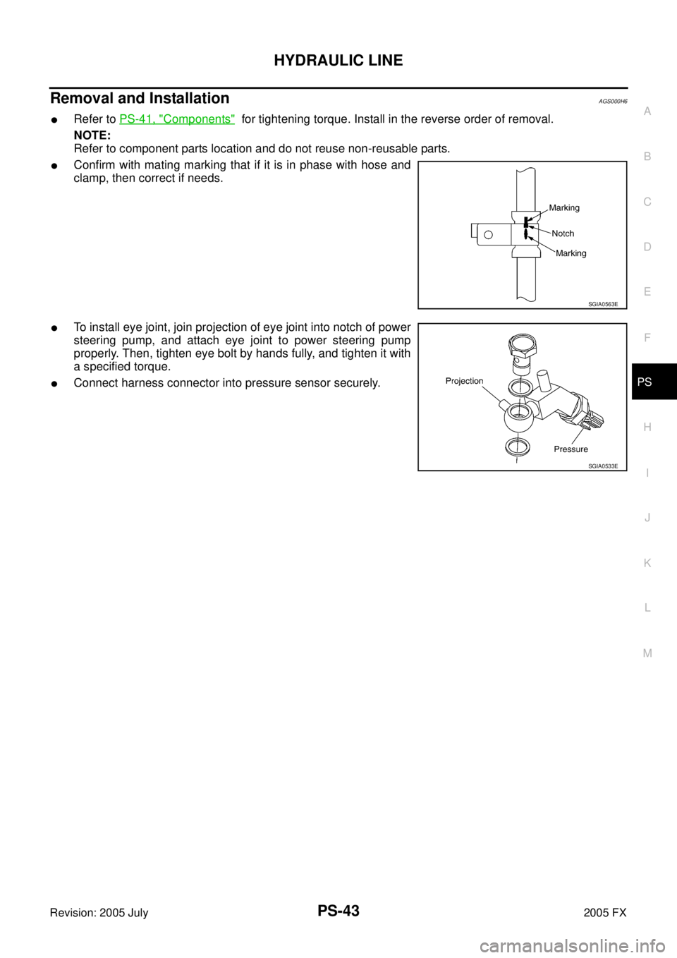
�Confirm with mating marking that if it is in phase with hose and
clamp, then correct if needs.
�To install eye joint, join projection of eye joint into notch of power
steering pump, and attach eye joint to power steering pump
properly. Then, tighten eye bolt by hands fully, and tighten it with
a specified torque.
�Connect harness connector into pressure sensor securely.
SGIA0563E
SGIA0533E
Page 4328 of 4731

WHEEL HUB RAX-5
C E F
G H
I
J
K L
M A
B
RAX
Revision: 2005 July 2005 FX
WHEEL HUBPFP:43202
On-Vehicle Inspection and ServiceADS000C4
Make sure the mounting conditions (looseness, back lash) of each component and component status (wear,
damage) are normal.
WHEEL BEARING INSPECTION
�Move wheel hub in the axial direction by hand. Make sure there is no looseness of wheel bearing.
�Rotate wheel hub and make sure there is no unusual noise or other irregular conditions. If there are any
irregular conditions, replace wheel bearings.
Removal and InstallationADS000C5
REMOVAL
1. Remove tire with power tool.
2. Remove brake caliper with power tool. Hang it in a place where it will not interfere with work. Refer to BR-
27, "Removal and Installation of Brake Caliper Assembly" .
NOTE:
�Avoid depressing brake pedal while brake caliper is removed.
3. Remove disc rotor.
4. Remove wheel sensor from axle. Refer to BRC-57, "
WHEEL SENSORS" .
CAUTION:
Do not pull on wheel sensor harness.
5. Remove cotter pin. Then remove lock nut from drive shaft.
6. Separate drive shaft from wheel hub and bearing assembly by lightly tapping the end with a suitable ham- mer and wood block. If it is hard to separate, use a suitable puller.
7. Remove fixing bolts of wheel hub and bearing assembly with power tool, then remove wheel hub and bearing assembly from axle.
8. Remove parking brake cable and parking brake shoe from back plate. Refer to PB-5, "
PARKING BRAKE
SHOE" and PB-3, "PARKING BRAKE CONTROL" .
9. Remove fixing nuts of anchor block with power tool, then remove anchor block and back plate from axle. Axial end play : 0 mm (0 in)
1. Drive shaft 2. Bushing 3. Axle
4. Back plate 5. Anchor block 6. Wheel bearing
7. Wheel hub 8. Cotter pin
SDIA1481E
Page 4329 of 4731

RAX-6
WHEEL HUB
Revision: 2005 July 2005 FX
10. Loosen fixing bolts and nuts of front lower link, radius rod, and rear lower link in side of suspension mem-
ber.
11. Set jack under rear lower link. Then remove fixing bolt in front lower link side of shock absorber with power tool.
12. Remove bolt and nut in axle side of rear lower link with power tool. Then remove coil spring. Refer to RSU-15, "
REAR LOWER LINK & COIL SPRING" .
13. Remove fixing bolts and nuts in axle side of front lower link, radius rod with power tool.
14. Remove suspension arm and cotter pin at axle, then loosen mounting nut.
15. Use a ball joint remover (suitable tool) to remove suspension arm from axle. Be careful not to damage ball joint boot.
CAUTION:
Tighten temporarily mounting nut to prevent damage to threads and to prevent ball joint remover
(suitable tool) from coming off.
16. Remove axle from vehicle.
INSPECTION AFTER REMOVAL
Ball Joint Inspection
Check for boot breakage, axial looseness, and torque of suspension arm ball joint. Refer to RSU-11,
"INSPECTION AFTER REMOVAL" .
INSTALLATION
�Refer to RAX-5, "Removal and Installation" for tightening torque. Install in the reverse order of removal.
NOTE:
Refer to component parts location and do not reuse non-reusable parts.
�Perform final tightening of installation position of suspension links (rubber bushing) under unladen condi-
tions with tires on level ground, Check wheel alignment. Refer to RSU-5, "
Wheel Alignment Inspection" .
�After adjusting wheel alignment, adjust neutral position of steering angle sensor. Refer to BRC-6, "Adjust-
ment of Steering Angle Sensor Neutral Position" .
Disassembly and AssemblyADS000C6
DISASSEMBLY
Wheel Bearing
CAUTION:
Do not disassemble if wheel bearing has no trouble.
1. Remove wheel bearing fixing bolts and anchor block fixing nuts, and remove wheel hub and bearing assembly, back plate and anchor block from axle.
2. Using a drift (SST) and a puller (suitable tool), press wheel hub out to remove from wheel bearing.
SDIA1482E
Page 4381 of 4731

RFD-12
SIDE OIL SEAL
Revision: 2005 July 2005 FX
SIDE OIL SEALPFP:33142
Removal and InstallationADS001AN
REMOVAL
1. Remove center muffler with a power tool. Refer to EX-3, "EXHAUST SYSTEM" .
2. Remove rear wheel sensor. Refer to BRC-57, "
WHEEL SENSORS" .
3. Remove drive shaft from final drive. Then suspend it by wire etc. Refer to RAX-9, "
REAR DRIVE SHAFT"
.
4. Install attachment to side flange, and then pull out the side flange with the sliding hammer.
�For VQ35DE models
NOTE:
Circular clip installation position: Final drive side
�For VK45DE models
NOTE:
Circular clip installation position: Final drive side
5. Remove side oil seal, using a flat-bladed screwdriver. CAUTION:
Be careful not to damage gear carrier.
INSTALLATION
1. Apply multi-purpose grease to side oil seal lips.
2. Install side oil seal until it becomes flush with the case end, using the drift.
CAUTION:
�Do not reuse oil seal.
�When installing, do not incline oil seal. Tool number A: KV40104100 ( — )
B: ST36230000 (J-25840-A)
SDIA1582E
Tool number A: KV40101000 ( — )B: ST36230000 (J-25840-A)
SDIA1583E
SDIA1584E
Tool number : KV38100200 (J-26233)
SDIA1585E
Page 4382 of 4731
SIDE OIL SEAL RFD-13
C E F
G H
I
J
K L
M A
B
RFD
Revision: 2005 July 2005 FX
3. Install side flange with the following procedure.
a. Attach the protector to side oil seal.
b. After the side flange is inserted and the serrated part of side gear has engaged the serrated part of flange, remove the pro-
tector.
c. Put a suitable drift on the center of side flange, then drive it until sound changes.
NOTE:
When installation is completed, driving sound of the side flange
turns into a sound which seems to affect the whole final drive.
d. Confirm that the dimension of the side flange installation (Mea- surement A) in the figure comes into the following.
4. Install drive shaft. Refer to RAX-9, "
REAR DRIVE SHAFT" .
5. Install rear wheel sensor. Refer to BRC-57, "
WHEEL SEN-
SORS" .
6. Install center muffler. Refer to EX-3, "
Removal and Installation" .
Tool number : KV38107900 (J-39352)
SDIA0822E
Measurement A: 326 - 328 mm (12.83 - 12.91 in)
SDIA1039E
Page 4383 of 4731
RFD-14
REAR FINAL DRIVE ASSEMBLY
Revision: 2005 July 2005 FX
REAR FINAL DRIVE ASSEMBLYPFP:38300
Removal and InstallationADS001AO
COMPONENTS
REMOVAL
1. Remove center muffler with a power tool. Refer to EX-3, "EXHAUST SYSTEM" .
2. Remove rear stabilizer bar with a power tool. Refer to FSU-16, "
STABILIZER BAR" .
3. Remove propeller shaft from the final drive. Refer to PR-9, "
Removal and Installation" .
4. Remove drive shaft from final drive. Then suspend it by wire etc. Refer to RAX-9, "
REAR DRIVE SHAFT" .
5. Remove breather hose from the final drive.
6. Remove rear wheel sensor. Refer to BRC-57, "
WHEEL SEN-
SORS" .
1. Rear final drive assembly 2. Upper stopper 3. Propeller shaft
4. Washer 5. Lower stopper 6. Drive shaft
PDIA0686E
SDIA1094E
Page 4415 of 4731

RSU-8
REAR SUSPENSION ASSEMBLY
Revision: 2005 July 2005 FX
Removal and InstallationAES000MM
REMOVAL
1. Remove tire with power tool.
2. Remove brake caliper with power tool. Hang it in a place where it will not interfere with work. Refer to BR-
26, "REAR DISC BRAKE" .
NOTE:
Avoid depressing brake pedal while brake caliper is removed.
3. Remove wheel sensor from rear final drive, then remove wheel sensor harness from rear suspension member.
4. Remove height sensor harness from rear suspension member (if equipped).
5. Remove center muffler and main muffler. Refer to EX-3, "
Removal and Installation" .
6. Remove stabilizer bar. Refer to RSU-16, "
Removal and Installation" .
7. Remove rear propeller shaft. Refer to PR-9, "
Removal and Installation" .
8. Separate attachments between parking brake cable and vehicle and rear suspension member.
9. Remove rear lower link and coil spring. Refer to RSU-15, "
Removal and Installation" .
10. Remove fixing bolt in lower side of shock absorber with power tool.
11. Set jack under rear final drive.
12. Remove fixing bolts and nuts of tunnel stay and member stay with power tool, then remove those parts from vehicle.
13. Remove fixing bolts and nuts of rear pin stay with power tool and then remove rear pin stay from vehicle.
14. Gradually lowering jack, remove rear suspension assembly.
INSTALLATION
�Refer to RSU-7, "Components" for tightening torque. Install in the reverse order of removal.
NOTE:
Refer to component parts location and do not reuse non-reusable parts.
�Perform final tightening of installation position of links (rubber bushing) under unladen conditions with tires
on level ground. Check wheel alignment. Refer to RSU-5, "
Wheel Alignment Inspection" .
�After adjusting wheel alignment, adjust neutral position of steering angle sensor. Refer to BRC-6, "Adjust-
ment of Steering Angle Sensor Neutral Position" .
1. Bushing 2. Mounting seal 3. Mounting seal bracket
4. Distance tube 5. Bound bumper cover 6. Bound bumper
7. Shock absorber 8. Upper seat 9. Coil spring
10. Rubber seat 11. Rear lower link 12. Axle
13. Cotter pin 14. Radius rod 15. Front lower link protector
16. Front lower link 17. Stopper 18. Shock absorber assembly
19. Suspension arm 20. Stabilizer connecting rod mounting bracket 21. Stabilizer connecting rod
22. Rear pin stay 23. Rear suspension member 24. Stabilizer bar
25. Stabilizer bushing 26. Stabilizer clamp 27. Member stay
28. Tunnel stay A: With height sensor B: Without height sensor
Refer to GI-10, "
Components" , for the symbols in the figure.