Page 4152 of 4731

ENGINE MAINTENANCE (VK45DE ENGINE) MA-25
C
D E
F
G H
I
J
K
M A
B
MA
Revision: 2005 July 2005 FX
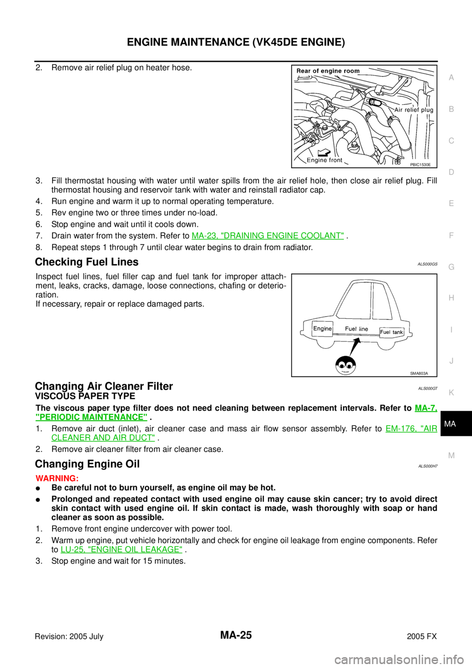
2. Remove air relief plug on heater hose.
3. Fill thermostat housing with water until water spills from the air relief hole, then close air relief plug. Fill
thermostat housing and reservoir tank with water and reinstall radiator cap.
4. Run engine and warm it up to normal operating temperature.
5. Rev engine two or three times under no-load.
6. Stop engine and wait until it cools down.
7. Drain water from the system. Refer to MA-23, "
DRAINING ENGINE COOLANT" .
8. Repeat steps 1 through 7 until clear water begins to drain from radiator.
Checking Fuel LinesALS000GS
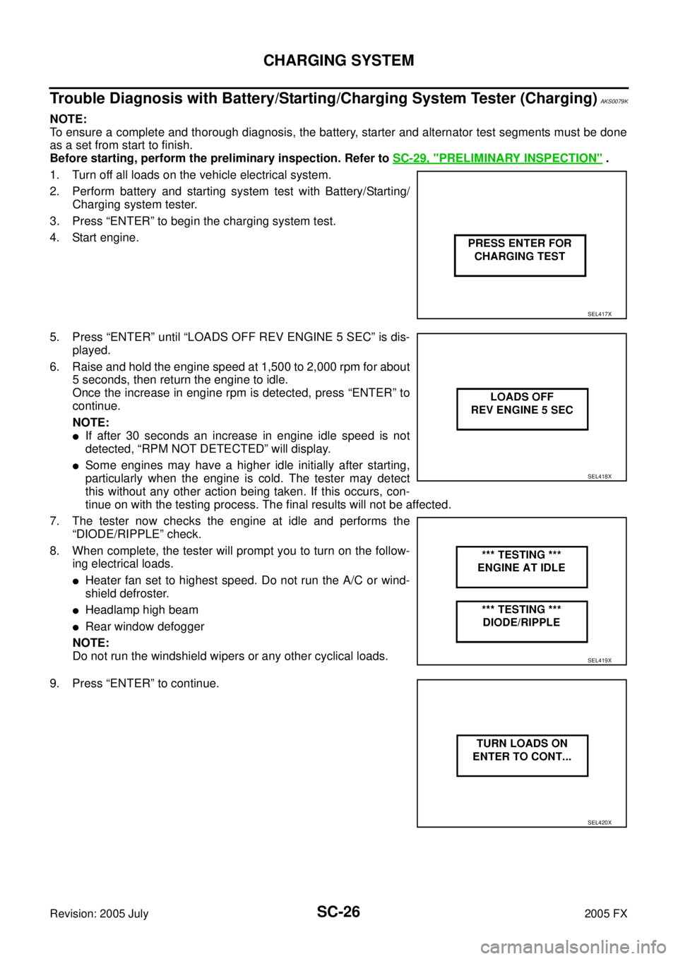
Inspect fuel lines, fuel filler cap and fuel tank for improper attach-
ment, leaks, cracks, damage, loose connections, chafing or deterio-
ration.
If necessary, repair or replace damaged parts.
Changing Air Cleaner FilterALS000GT
VISCOUS PAPER TYPE
The viscous paper type filter does not need cleaning between replacement intervals. Refer to MA-7,
"PERIODIC MAINTENANCE" .
1. Remove air duct (inlet), air cleaner case and mass air flow sensor assembly. Refer to EM-176, "
AIR
CLEANER AND AIR DUCT" .
2. Remove air cleaner filter from air cleaner case.
Changing Engine OilALS000H7
WARNING:
�Be careful not to burn yourself, as engine oil may be hot.
�Prolonged and repeated contact with used engine oil may cause skin cancer; try to avoid direct
skin contact with used engine oil. If skin contact is made, wash thoroughly with soap or hand
cleaner as soon as possible.
1. Remove front engine undercover with power tool.
2. Warm up engine, put vehicle horizontally and check for engine oil leakage from engine components. Refer to LU-25, "
ENGINE OIL LEAKAGE" .
3. Stop engine and wait for 15 minutes.
PBIC1530E
SMA803A
Page 4245 of 4731

PG-68
HARNESS
Revision: 2005 July 2005 FX
H/AIM LT Headlamp Aiming Control System
H/LAMP LT Headlamp
HORN WW Horn
HSEAT SE Heated Seat
I/KEY BL Intelligent Key System
I/MIRR GW Inside Mirror (Auto Anti-Dazzling Mirror)
IATS EC Intake Air Temperature Sensor
ICC ACS Intelligent Cruise Control System
ICC/BS EC ICC Brake Switch
ICC/SW EC ICC Steering Switch
ICCBOF EC ICC Brake Switch
IGNSYS EC Ignition System
ILL LT Illumination
INF/D AV Vehicle Information and Integrated Switch System
INJECT EC Injector
IVCB1 EC Intake Valve Timing Control Solenoid Valve Bank 1
IVCB2 EC Intake Valve Timing Control Solenoid Valve Bank 2
IVCSB1 EC Intake Valve Timing Control Position Sensor Bank 1
IVCSB2 EC Intake Valve Timing Control Position Sensor Bank 2
IVTB1 EC Intake Valve Timing Control System (Bank 1)
IVTB2 EC Intake Valve Timing Control System (Bank 2)
KEYLES BL Remote Keyless Entry System
KS EC Knock Sensor
LDW DI Lane Departure Warning System
M/ANT AV Manual Antenna
MAFS EC Mass Air Flow Sensor
MAIN AT Main Power Supply and Ground Circuit
MAIN EC Main Power Supply and Ground Circuit
MES AV Mobile Entertainment System
METER DI Speedometer, Tachometer, Temp. and Fuel Gauges
MIL/DL EC MIL & Data Link Connectors
MIRROR GW Power Door Mirror
MMSW AT Manual Mode Switch
NATS BL Nissan Anti-Theft System
NAVI AV Navigation System
NONDTC AT Non-Detective Items
O2H1B1 EC Heated Oxygen Sensor 1 Heater Bank 1
O2H1B2 EC Heated Oxygen Sensor 1 Heater Bank 2
O2H2B1 EC Heated Oxygen Sensor 2 Heater Bank 1
O2H2B2 EC Heated Oxygen Sensor 2 Heater Bank 2
O2S1B1 EC Heated Oxygen Sensor 1 Bank 1
O2S1B2 EC Heated Oxygen Sensor 1 Bank 2
O2S2B1 EC Heated Oxygen Sensor 2 Bank 1
O2S2B2 EC Heated Oxygen Sensor 2 Bank 2 Code Section Wiring Diagram Name
Page 4461 of 4731

SC-26
CHARGING SYSTEM
Revision: 2005 July 2005 FX
Trouble Diagnosis with Battery/Starting/Charging System Tester (Charging)AKS0079K
NOTE:
To ensure a complete and thorough diagnosis, the battery, starter and alternator test segments must be done
as a set from start to finish.
Before starting, perform the preliminary inspection. Refer to SC-29, "
PRELIMINARY INSPECTION" .
1. Turn off all loads on the vehicle electrical system.
2. Perform battery and starting system test with Battery/Starting/ Charging system tester.
3. Press “ENTER” to begin the charging system test.
4. Start engine.
5. Press “ENTER” until “LOADS OFF REV ENGINE 5 SEC” is dis- played.
6. Raise and hold the engine speed at 1,500 to 2,000 rpm for about 5 seconds, then return the engine to idle.
Once the increase in engine rpm is detected, press “ENTER” to
continue.
NOTE:
�If after 30 seconds an increase in engine idle speed is not
detected, “RPM NOT DETECTED” will display.
�Some engines may have a higher idle initially after starting,
particularly when the engine is cold. The tester may detect
this without any other action being taken. If this occurs, con-
tinue on with the testing process. The final results will not be affected.
7. The tester now checks the engine at idle and performs the “DIODE/RIPPLE” check.
8. When complete, the tester will prompt you to turn on the follow- ing electrical loads.
�Heater fan set to highest speed. Do not run the A/C or wind-
shield defroster.
�Headlamp high beam
�Rear window defogger
NOTE:
Do not run the windshield wipers or any other cyclical loads.
9. Press “ENTER” to continue.
SEL417X
SEL418X
SEL419X
SEL420X
Page 4577 of 4731
SE-104
FRONT SEAT
Revision: 2005 July 2005 FX
3. Remove the stay securing the inner cloth.
4. Remove the headrest.
5. Remove the headrest holder. From the back of the seatback, press the headrest holder tab of
the stay pipe hole to disengage. Then pull the headrest holder
up to remove.
NOTE:
Before installing the headrest holder, check its orientation (front,
rear, left and right).
6. Remove the heated seat connector.
7. After removing the seatback trim and pad, remove the hog rings to separate the trim, pad, and seatback heater unit.
INSTALLATION OF SEATBACK TRIM AND PAD
Install in the reverse order of removal.
REMOVAL OF SEAT CUSHION TRIM AND PAD
1. Remove the seat cushion inner finisher.
PIIA6048E
PIIA6050E
PIIA6049E
PIIA6052E
Page 4578 of 4731
FRONT SEAT SE-105
C
D E
F
G H
J
K L
M A
B
SE
Revision: 2005 July 2005 FX
2. Remove the velcro and retainer.
3. Remove the seat harness connector.
4. Remove the seatback frame.
5. Remove the reclining device assembly.
6. Remove the power seat switch assembly.
7. Remove the retainer and clip.
8. After removing the seat cushion trim and pad, remove the hog rings to separate the trim and pad and the seat cushion heater unit.
INSTALLATION OF SEAT CUSHION TRIM AND PAD
Install in the reverse order of removal.
PIIA6053E
PIIA6054E
PIIA1160E
PIIA6055E