Page 2865 of 4731
![INFINITI FX35 2005 Service Manual EM-30
[VQ35DE]
OIL PAN AND OIL STRAINER
Revision: 2005 July 2005 FX
OIL PAN AND OIL STRAINERP F P : 1111 0
Components (2WD Model)ABS00E5Z
Removal and Installation (2WD Model)ABS004U5
REMOVAL
CAUTION:](/manual-img/42/57020/w960_57020-2864.png "INFINITI FX35 2005 Service Manual EM-30
[VQ35DE]
OIL PAN AND OIL STRAINER
Revision: 2005 July 2005 FX
OIL PAN AND OIL STRAINERP F P : 1111 0
Components (2WD Model)ABS00E5Z
Removal and Installation (2WD Model)ABS004U5
REMOVAL
CAUTION:")
EM-30
[VQ35DE]
OIL PAN AND OIL STRAINER
Revision: 2005 July 2005 FX
OIL PAN AND OIL STRAINERP F P : 1111 0
Components (2WD Model)ABS00E5Z
Removal and Installation (2WD Model)ABS004U5
REMOVAL
CAUTION:
To avoid the danger of being scalded, never drain engine oil when the engine is hot.
NOTE:
To remove oil pan (lower) only, take step 5, then step 20. Removal of step 1, hood assembly (step 2) and step
4 are unnecessary.
1. Remove front tire.
2. Remove hood assembly. Refer to BL-13, "
HOOD" .
3. Remove front and rear engine undercover with power tool.
4. Remove front cross bar with power tool. FSU-6, "
FRONT SUSPENSION ASSEMBLY" .
5. Drain engine oil. Refer to LU-9, "
Changing Engine Oil" .
CAUTION:
�Perform this step when the engine is cold.
1. Oil pan gasket (rear) 2. Oil pan (upper) 3. O-ring
4. Oil pan gasket (front) 5. Oil filter 6. Connector bolt
7. Oil cooler 8. O-ring 9. Relief valve
10. Oil pressure switch 11. Bracket 12. Oil strainer
13. Drain plug 14. Drain plug washer 15. Oil pan (lower)
16. Rear plate 17. Crankshaft position sensor (POS) 18. Seal rubber
19. Rear cover plate
SBIA0587E
Page 2866 of 4731
![INFINITI FX35 2005 Service Manual OIL PAN AND OIL STRAINER EM-31
[VQ35DE]
C
D E
F
G H
I
J
K L
M A
EM
Revision: 2005 July 2005 FX
�Do not spill engine oil on drive belts.
6. Drain engine coolant. Refer to CO-11, "
Chang](/manual-img/42/57020/w960_57020-2865.png "INFINITI FX35 2005 Service Manual OIL PAN AND OIL STRAINER EM-31
[VQ35DE]
C
D E
F
G H
I
J
K L
M A
EM
Revision: 2005 July 2005 FX
�Do not spill engine oil on drive belts.
6. Drain engine coolant. Refer to CO-11, \"
Chang")
OIL PAN AND OIL STRAINER EM-31
[VQ35DE]
C
D E
F
G H
I
J
K L
M A
EM
Revision: 2005 July 2005 FX
�Do not spill engine oil on drive belts.
6. Drain engine coolant. Refer to CO-11, "
Changing Engine Coolant" .
CAUTION:
�Perform this step when the engine is cold.
�Do not spill engine coolant on drive belts.
7. Remove engine cover with power tool. Refer to EM-19, "
INTAKE MANIFOLD COLLECTOR" .
8. Remove air hose from air duct to mass air flow sensor side and electric throttle control actuator side. Refer to EM-17, "
AIR CLEANER AND AIR DUCT" .
9. Removal engine rear lower slinger, and install engine rear slinger [SST: 10006 31U00 ( — )] to sling engine assembly for positioning. Refer to EM-8, "
Special Service Tools" .
10. Remove front suspension member. Refer to FSU-17, "
FRONT SUSPENSION MEMBER" .
11. Remove drive belts. Refer to EM-15, "
DRIVE BELTS" .
12. Remove alternator stay. Refer to SC-23, "
CHARGING SYSTEM" .
13. Remove starter motor. Refer to SC-10, "
STARTING SYSTEM" .
14. Remove idler pulley and bracket assembly. Refer to EM-64, "
TIMING CHAIN" .
15. Disconnect oil cooler water hoses, and remove oil cooler water pipe mounting bolt. Refer to LU-14, "
OIL
COOLER" .
16. Disconnect A/T fluid cooler hoses, and remove A/T fluid cooler tube. Refer to AT- 2 7 0 , "
TRANSMISSION
ASSEMBLY" .
17. Remove crankshaft position sensor (POS).
CAUTION:
�Handle carefully to avoid dropping and shocks.
�Do not disassemble.
�Do not allow metal powder to adhere to magnetic part at sensor tip.
�Do not place sensors in a location where they are exposed to magnetism.
18. Remove oil filter, as necessary. Refer to LU-10, "
OIL FILTER" .
19. Remove oil cooler, as necessary. Refer to LU-14, "
OIL COOLER" .
20. Remove oil pan (lower) as follows:
a. Loosen mounting bolts in reverse order as shown in the figure to remove.
b. Insert the seal cutter [SST] between oil pan (upper) and oil pan (lower).
CAUTION:
�Be careful not to damage the mating surfaces.
�Do not insert a screwdriver, this will damage the mating
surfaces.
c. Slide the seal cutter by tapping on the side of tool with a ham- mer. Remove oil pan (lower). Slinger bolts:
: 28.0 N·m (2.9 kg-m, 21 ft-lb)
PBIC0782E
SEM960F
Page 2870 of 4731
OIL PAN AND OIL STRAINER EM-35
[VQ35DE]
C
D E
F
G H
I
J
K L
M A
EM
Revision: 2005 July 2005 FX
�Tighten mounting bolts in numerical order as shown in the fig-
ure.
4. Install oil pan drain plug.
�Refer to the figure of components of former page for installation direction of drain plug washer. Refer to
EM-30, "
Components (2WD Model)" .
5. Install in the reverse order of removal after this step.
NOTE:
At least 30 minutes after oil pan is installed, pour engine oil.
INSPECTION AFTER INSTALLATION
1. Check the engine oil level and adjust engine oil. Refer to LU-7, "ENGINE OIL" .
2. Start engine, and check there is no leak of engine oil.
3. Stop engine and wait for 10 minutes.
4. Check the engine oil level again. Refer to LU-7, "
ENGINE OIL" .
Components (AWD Model)ABS00E60
PBIC0782E
SBIA0567E
Page 2871 of 4731
![INFINITI FX35 2005 Service Manual EM-36
[VQ35DE]
OIL PAN AND OIL STRAINER
Revision: 2005 July 2005 FX
Removal and Installation (AWD Model)ABS00E3Q
REMOVAL
CAUTION:
To avoid the danger of being scalded, never drain engine oil when the](/manual-img/42/57020/w960_57020-2870.png "INFINITI FX35 2005 Service Manual EM-36
[VQ35DE]
OIL PAN AND OIL STRAINER
Revision: 2005 July 2005 FX
Removal and Installation (AWD Model)ABS00E3Q
REMOVAL
CAUTION:
To avoid the danger of being scalded, never drain engine oil when the")
EM-36
[VQ35DE]
OIL PAN AND OIL STRAINER
Revision: 2005 July 2005 FX
Removal and Installation (AWD Model)ABS00E3Q
REMOVAL
CAUTION:
To avoid the danger of being scalded, never drain engine oil when the engine is hot.
NOTE:
To remove oil pan (lower) only, take step 5, then step 24. Removal of step 1, hood assembly (step 2) and step
4 are unnecessary.
1. Remove front tire.
2. Remove hood assembly. Refer to BL-13, "
HOOD" .
3. Remove front and rear engine undercover with power tool.
4. Remove front cross bar with power tool. Refer to FSU-6, "
FRONT SUSPENSION ASSEMBLY" .
5. Drain engine oil. Refer to LU-9, "
Changing Engine Oil" .
CAUTION:
�Perform this step when the engine is cold.
�Do not spill engine oil on drive belts.
6. Drain engine coolant. Refer to CO-11, "
Changing Engine Coolant" .
CAUTION:
�Perform this step when the engine is cold.
�Do not spill engine coolant on drive belts.
7. Remove engine cover with power tool. Refer to EM-19, "
INTAKE MANIFOLD COLLECTOR" .
8. Remove air hose from air duct to mass air flow sensor side and electric throttle control actuator side. Refer to EM-17, "
AIR CLEANER AND AIR DUCT" .
9. Remove drive belts. Refer to EM-15, "
DRIVE BELTS" .
10. Remove front drive shaft (LH and RH) and side shaft. Refer to FAX-12, "
FRONT DRIVE SHAFT" .
11. Remove side shaft. Refer to FFD-12, "
FRONT FINAL DRIVE ASSEMBLY" .
12. Removal engine rear lower slinger, and install engine rear slinger [SST: 10006 31U00 ( — )] to sling engine assembly for positioning. Refer to EM-8, "
Special Service Tools" .
13. Remove front suspension member. Refer to Refer to FSU-17, "
FRONT SUSPENSION MEMBER" .
14. Remove engine mounting bracket, engine mounting bracket (lower) and insulator. Refer to EM-112,
"ENGINE ASSEMBLY" .
15. Remove front propeller shaft. Refer to PR-4, "
FRONT PROPELLER SHAFT" .
16. Remove oil filter and oil filter bracket. Refer to LU-12, "
OIL FILTER BRACKET (AWD)" .
17. Remove alternator stay. Refer to SC-23, "
CHARGING SYSTEM" .
18. Remove idler pulley and bracket. Refer to EM-15, "
DRIVE BELTS" .
19. Disconnect oil cooler water hoses, and remove oil cooler water pipe mounting bolt. Refer to LU-14, "
OIL
COOLER" .
20. Disconnect A/T fluid cooler hoses, and remove A/T fluid cooler tube. Refer to AT- 2 7 0 , "
TRANSMISSION
ASSEMBLY" .
21. Remove front final drive assembly. Refer to FFD-12, "
FRONT FINAL DRIVE ASSEMBLY" .
22. Remove starter motor. Refer to SC-10, "
STARTING SYSTEM" .
23. Remove crankshaft position sensor (POS).
1. Oil pan gasket (rear) 2. Oil pan (upper) 3. O-ring
4. Oil pan gasket (front) 5. Oil filter 6. Connector bolt
7. Oil cooler 8. O-ring 9. Relief valve
10. Oil filter bracket 11. Oil filter bracket gasket 12. Oil strainer
13. Drain plug 14. Drain plug washer 15. Oil pan (lower)
16. Rear plate 17. Crankshaft position sensor (POS) 18 O-ring (small)
19. O-ring (large) 20. Axle pipe
Slinger bolts: : 28.0 N·m (2.9 kg-m, 21 ft-lb)
Page 2873 of 4731
EM-38
[VQ35DE]
OIL PAN AND OIL STRAINER
Revision: 2005 July 2005 FX
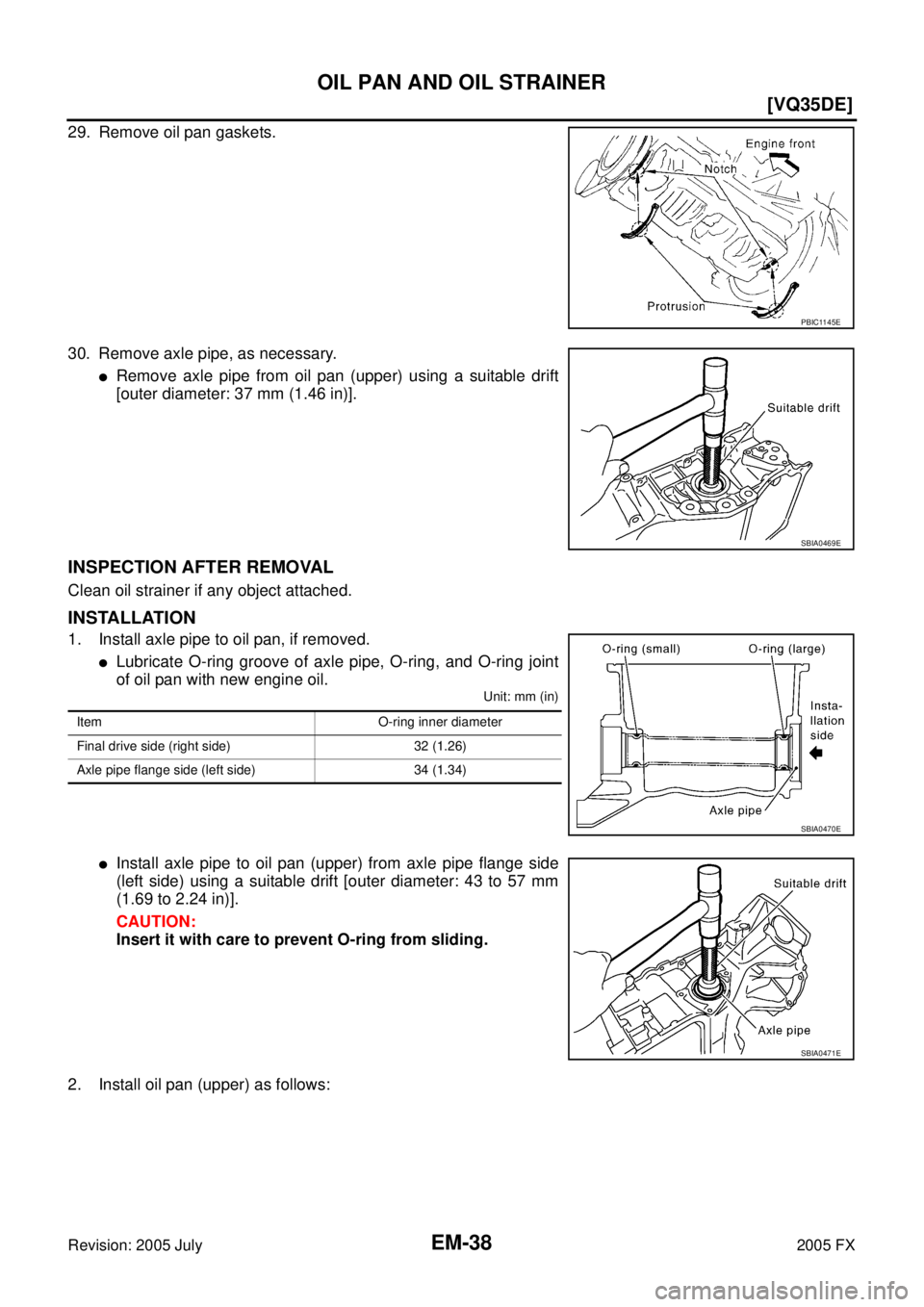
29. Remove oil pan gaskets.
30. Remove axle pipe, as necessary.
�Remove axle pipe from oil pan (upper) using a suitable drift
[outer diameter: 37 mm (1.46 in)].
INSPECTION AFTER REMOVAL
Clean oil strainer if any object attached.
INSTALLATION
1. Install axle pipe to oil pan, if removed.
�Lubricate O-ring groove of axle pipe, O-ring, and O-ring joint
of oil pan with new engine oil.
Unit: mm (in)
�Install axle pipe to oil pan (upper) from axle pipe flange side
(left side) using a suitable drift [outer diameter: 43 to 57 mm
(1.69 to 2.24 in)].
CAUTION:
Insert it with care to prevent O-ring from sliding.
2. Install oil pan (upper) as follows:
PBIC1145E
SBIA0469E
Item O-ring inner diameter
Final drive side (right side) 32 (1.26)
Axle pipe flange side (left side) 34 (1.34)
SBIA0470E
SBIA0471E
Page 2876 of 4731
![INFINITI FX35 2005 Service Manual OIL PAN AND OIL STRAINER EM-41
[VQ35DE]
C
D E
F
G H
I
J
K L
M A
EM
Revision: 2005 July 2005 FX
b. Apply a continuous bead of liquid gasket with the tube presser
[SST: WS39930000 ( — )]](/manual-img/42/57020/w960_57020-2875.png "INFINITI FX35 2005 Service Manual OIL PAN AND OIL STRAINER EM-41
[VQ35DE]
C
D E
F
G H
I
J
K L
M A
EM
Revision: 2005 July 2005 FX
b. Apply a continuous bead of liquid gasket with the tube presser
[SST: WS39930000 ( — )]")
OIL PAN AND OIL STRAINER EM-41
[VQ35DE]
C
D E
F
G H
I
J
K L
M A
EM
Revision: 2005 July 2005 FX
b. Apply a continuous bead of liquid gasket with the tube presser
[SST: WS39930000 ( — )] to the oil pan (lower) as shown in
the figure.
Use Genuine RTV Silicone Sealant or equivalent. Refer to
GI-48, "
RECOMMENDED CHEMICAL PRODUCTS AND
SEALANTS" .
CAUTION:
Attaching should be done within 5 minutes after coating.
c. Install oil pan (lower).
�Tighten mounting bolts in numerical order as shown in the fig-
ure.
5. Install oil pan drain plug.
�Refer to the figure of components of former page for installation direction of drain plug washer. Refer to
EM-35, "
Components (AWD Model)" .
6. Install in the reverse order of removal after this step.
NOTE:
At least 30 minutes after oil pan is installed, pour engine oil.
INSPECTION AFTER INSTALLATION
1. Check the engine oil level and adjust engine oil. Refer to LU-7, "ENGINE OIL" .
2. Start engine, and check there is no leak of engine oil.
3. Stop engine and wait for 10 minutes.
4. Check the engine oil level again. Refer to LU-7, "
ENGINE OIL" .
PBIC2657E
PBIC0782E
Page 2877 of 4731
EM-42
[VQ35DE]
IGNITION COIL
Revision: 2005 July 2005 FX
IGNITION COILPFP:22448
ComponentsABS00E61
Removal and InstallationABS004U6
REMOVAL
1. Remove engine cover with power tool. Refer to EM-19, "INTAKE MANIFOLD COLLECTOR" .
2. Remove air duct (At the left bank side, remove ignition coil). Refer to EM-17, "
AIR CLEANER AND AIR
DUCT" .
3. Move aside harness, harness bracket, and hoses located above ignition coil.
4. Disconnect harness connector from ignition coil.
5. Remove ignition coil. CAUTION:
Do not shock it.
INSTALLATION
Installation is the reverse order of removal.
1. Ignition coil 2. Spark plug
SBIA0568E
Page 2878 of 4731
![INFINITI FX35 2005 Service Manual SPARK PLUG (PLATINUM-TIPPED TYPE) EM-43
[VQ35DE]
C
D E
F
G H
I
J
K L
M A
EM
Revision: 2005 July 2005 FX
SPARK PLUG (PLATINUM-TIPPED TYPE)PFP:22401
ComponentsABS00E62
Removal and Installat](/manual-img/42/57020/w960_57020-2877.png "INFINITI FX35 2005 Service Manual SPARK PLUG (PLATINUM-TIPPED TYPE) EM-43
[VQ35DE]
C
D E
F
G H
I
J
K L
M A
EM
Revision: 2005 July 2005 FX
SPARK PLUG (PLATINUM-TIPPED TYPE)PFP:22401
ComponentsABS00E62
Removal and Installat")
SPARK PLUG (PLATINUM-TIPPED TYPE) EM-43
[VQ35DE]
C
D E
F
G H
I
J
K L
M A
EM
Revision: 2005 July 2005 FX
SPARK PLUG (PLATINUM-TIPPED TYPE)PFP:22401
ComponentsABS00E62
Removal and InstallationABS004WI
REMOVAL
1. Remove engine cover with power tool. Refer to EM-19, "INTAKE MANIFOLD COLLECTOR" .
2. Remove ignition coil. Refer to EM-42, "
IGNITION COIL" .
3. Remove spark plug with a spark plug wrench (commercial ser- vice tool).
INSPECTION AFTER REMOVAL
Use the standard type spark plug for normal condition.
The hot type spark plug is suitable when fouling occurs with the standard type spark plug under conditions
such as:
�Frequent engine starts
�Low ambient temperatures
The cold type spark plug is suitable when spark knock occurs with the standard type spark plug under condi-
tions such as:
�Extended highway driving
�Frequent high engine revolution
1. Ignition coil 2. Spark plug
SBIA0568E
SEM294A
Make NGK
Standard type PLFR5A-11
Hot type PLFR4A-11
Cold type PLFR6A-11
Gap (Nominal) : 1.1 mm (0.043 in)

![INFINITI FX35 2005 Service Manual EM-42
[VQ35DE]
IGNITION COIL
Revision: 2005 July 2005 FX
IGNITION COILPFP:22448
ComponentsABS00E61
Removal and InstallationABS004U6
REMOVAL
1. Remove engine cover with power tool. Refer to EM-19, "INT](/manual-img/42/57020/w960_57020-2876.png "INFINITI FX35 2005 Service Manual EM-42
[VQ35DE]
IGNITION COIL
Revision: 2005 July 2005 FX
IGNITION COILPFP:22448
ComponentsABS00E61
Removal and InstallationABS004U6
REMOVAL
1. Remove engine cover with power tool. Refer to EM-19, \"INT")