Page 4285 of 4731
PS-10
STEERING WHEEL
Revision: 2005 July 2005 FX
STEERING WHEELPFP:48430
On-Vehicle Inspection and ServiceAGS000GW
CHECKING CONDITION OF INSTALLATION
�Check installation condition of steering gear assembly, front suspension, axle and steering column.
�Check if movement exists when steering wheel is moved up and down, to the left and right and to the axial
direction.
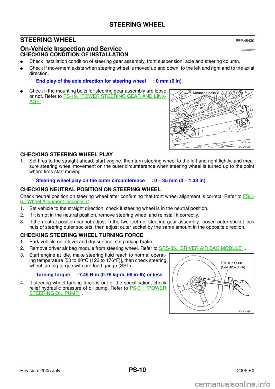
�Check if the mounting bolts for steering gear assembly are loose
or not. Refer to PS-19, "
POWER STEERING GEAR AND LINK-
AGE" .
CHECKING STEERING WHEEL PLAY
1. Set tires to the straight ahead, start engine, then turn steering wheel to the left and right lightly, and mea-
sure steering wheel movement on the outer circumference when steering wheel is turned up to the point
where tires start moving.
CHECKING NEUTRAL POSITION ON STEERING WHEEL
Check neutral position on steering wheel after confirming that front wheel alignment is correct. Refer to FSU-
6, "Wheel Alignment Inspection" .
1. Set vehicle to the straight direction, check if steering wheel is in the neutral position.
2. If it is not in the neutral position, remove steering wheel and reinstall it correctly.
3. If the neutral position cannot adjust in the two teeth of steering gear assembly, loosen outer socket lock nuts of steering outer sockets, then adjust outer socket by the same amount in the opposite direction.
CHECKING STEERING WHEEL TURNING FORCE
1. Park vehicle on a level and dry surface, set parking brake.
2. Remove driver air bag module from steering wheel. Refer to SRS-35, "
DRIVER AIR BAG MODULE" .
3. Start engine at idle, make steering fluid reach to normal operat- ing temperature [50 to 80 °C (122 to 176 °F)], then check steering
wheel turning torque with pre-load gauge (SST).
4. If steering wheel turning force is out of the specification, check relief hydraulic pressure of oil pump. Refer to PS-31, "
POWER
STEERING OIL PUMP" .
End play of the axle direction for steering wheel : 0 mm (0 in)
SGIA0546E
Steering wheel play on the outer circumference : 0
− 35 mm (0 − 1.38 in)
Turning torque : 7.45 N·m (0.76 kg-m, 66 in-lb) or less
SGIA0459E
Page 4328 of 4731
WHEEL HUB RAX-5
C E F
G H
I
J
K L
M A
B
RAX
Revision: 2005 July 2005 FX
WHEEL HUBPFP:43202
On-Vehicle Inspection and ServiceADS000C4
Make sure the mounting conditions (looseness, back lash) of each component and component status (wear,
damage) are normal.
WHEEL BEARING INSPECTION
�Move wheel hub in the axial direction by hand. Make sure there is no looseness of wheel bearing.
�Rotate wheel hub and make sure there is no unusual noise or other irregular conditions. If there are any
irregular conditions, replace wheel bearings.
Removal and InstallationADS000C5
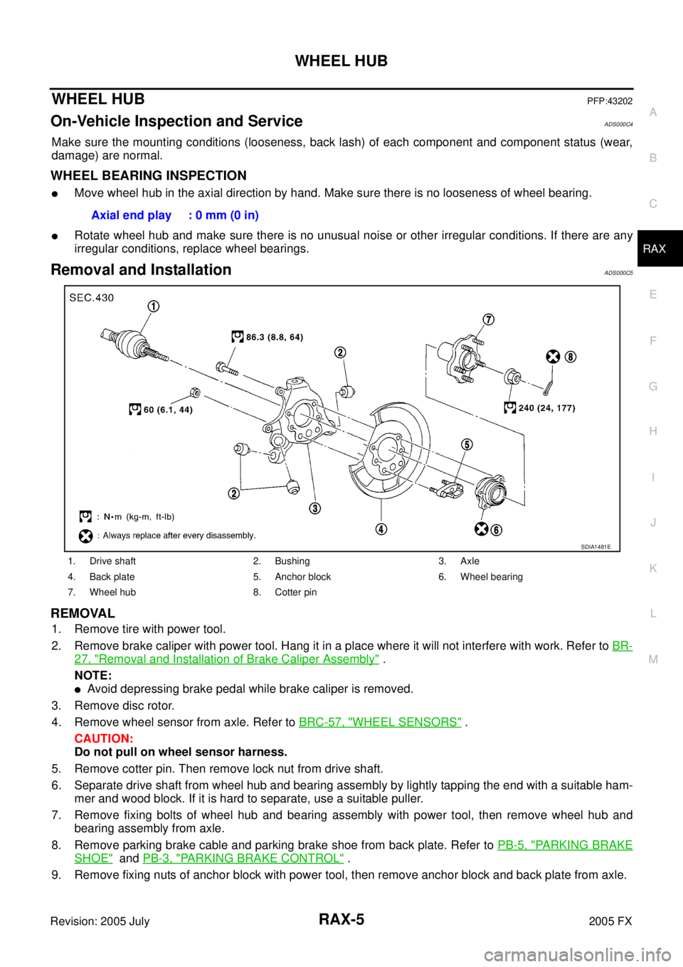
REMOVAL
1. Remove tire with power tool.
2. Remove brake caliper with power tool. Hang it in a place where it will not interfere with work. Refer to BR-
27, "Removal and Installation of Brake Caliper Assembly" .
NOTE:
�Avoid depressing brake pedal while brake caliper is removed.
3. Remove disc rotor.
4. Remove wheel sensor from axle. Refer to BRC-57, "
WHEEL SENSORS" .
CAUTION:
Do not pull on wheel sensor harness.
5. Remove cotter pin. Then remove lock nut from drive shaft.
6. Separate drive shaft from wheel hub and bearing assembly by lightly tapping the end with a suitable ham- mer and wood block. If it is hard to separate, use a suitable puller.
7. Remove fixing bolts of wheel hub and bearing assembly with power tool, then remove wheel hub and bearing assembly from axle.
8. Remove parking brake cable and parking brake shoe from back plate. Refer to PB-5, "
PARKING BRAKE
SHOE" and PB-3, "PARKING BRAKE CONTROL" .
9. Remove fixing nuts of anchor block with power tool, then remove anchor block and back plate from axle. Axial end play : 0 mm (0 in)
1. Drive shaft 2. Bushing 3. Axle
4. Back plate 5. Anchor block 6. Wheel bearing
7. Wheel hub 8. Cotter pin
SDIA1481E
Page 4669 of 4731
TF-36
TROUBLE DIAGNOSIS FOR SYMPTOMS
Revision: 2005 July 2005 FX
3. CHECK SYSTEM FOR AWD SOLENOID
Perform trouble diagnosis for AWD solenoid system. Refer to TF-28, "
AWD Solenoid" .
OK or NG
OK >> GO TO 4.
NG >> Repair or replace damaged parts.
4. CHECK ELECTRIC CONTROLLED COUPLING
1. Turn ignition switch “OFF”.
2. Set the selector lever to “N” (neutral) position and disengage the parking brake.
3. Lift up the vehicle.
4. Rotate the rear propeller shaft by hand.
5. Hold front propeller shaft lightly.
Does front propeller shaft rotate?
YES >> Replace electric controlled coupling for mechanical malfunction (clutch sticking etc.). Refer to TF-
45, "Disassembly and Assembly" .
NO >> GO TO 5.
5. SYMPTOM CHECK
Check again.
OK or NG
OK >> INSPECTION END
NG >> GO TO 6.
6. CHECK AWD CONTROL UNIT
Check AWD control unit input/output signal. Refer to TF-20, "
AWD Control Unit Input/Output Signal Reference
Va l u e s" .
OK or NG
OK >> INSPECTION END
NG >> Check AWD control unit pin terminals for damage or loose connection with harness connector. If
any items are damaged, repair or replace damaged parts.
Vehicle Does Not Enter AWD Mode Even Though AWD Warning Lamp Turned to
OFF
ADS000U0
DIAGNOSTIC PROCEDURE
1. CHECK AWD SOLENOID
Check AWD solenoid. Refer to TF-30, "
COMPONENT INSPECTION" .
OK or NG
OK >> GO TO 2.
NG >> Replace electric controlled coupling for malfunction of AWD solenoid. Refer to TF-45, "
Disassem-
bly and Assembly" .
2. CHECK AWD CONTROL UNIT
Check AWD control unit input/output signal. Refer to TF-20, "
AWD Control Unit Input/Output Signal Reference
Va l u e s" .
OK or NG
OK >> GO TO 3.
NG >> Check AWD control unit pin terminals for damage or loose connection with harness connector. If any items are damaged, repair or replace damaged parts.