Page 3265 of 4731
 laws and local laws regarding the towing")
GI-44
TOW TRUCK TOWING
Revision: 2005 July 2005 FX
TOW TRUCK TOWINGPFP:00000
Tow Truck TowingAAS000EH
CAUTION:
�All applicable state or Provincial (in Canada) laws and local laws regarding the towing operation
must be obeyed.
�It is necessary to use proper towing equipment to avoid possible damage to the vehicle during
towing operation. Towing is in accordance with Towing Procedure Manual at dealer.
�Always attach safety chains before towing.
�When towing, make sure that the transmission, steering system and powertrain are in good order.
If any unit is damaged, dollies must be used.
�Never tow an automatic transmission model from the rear (that is backward) with four wheels on
the ground. This may cause serious and expensive damage to the transmission.
2WD MODELS
INFINITI recommends that vehicle be towed with the driving (rear) wheels off the ground or that a dolly be
used as illustrated.
CAUTION:
�Never tow automatic transmission models with the rear wheels on the ground or four wheels on
the ground (forward or backward), as this may cause serious and expensive damage to the trans-
mission.
If it is necessary to tow the vehicle with the front wheels raised, always use towing dollies under
the rear wheels.
�When towing rear wheel drive models with the front wheels on the ground or on towing dollies:
–Turn the ignition key to the OFF position, and secure the steering wheel in a straight ahead posi-
tion with a rope or similar device.Never secure the steering wheel by turning the ignition key to the
LOCK position. This may damage the steering lock mechanism.
–Move the selector lever to the N (Neutral) position.
�When the battery of vehicle equipped with the Intelligent Key system is discharged, your vehicle
should be towed with the front wheels on towing dollies or place the vehicle on a flat bed truck.
If the speed or distance must necessarily be greater, remove the propeller shaft before towing to prevent dam-
age to the transmission.
PAIA0097E
Page 3306 of 4731

POWER WINDOW SYSTEM GW-29
C
D E
F
G H
J
K L
M A
B
GW
Revision: 2005 July 2005 FX
Terminal and Reference Value for Power Window Main Switch / With Front
Power Window Anti-pinch System
AIS004Q3
Terminal Wire color Item Condition Voltage [V]
(Approx.)
1Y Rear LH power window
UP signal When rear LH switch in
power window main switch is
UP at operated. Battery voltage
2 SB Limit switch and encoder ground — 0
3R Rear LH power window
DOWN signal When rear LH switch in
power window main switch is
DOWN at operated. Battery voltage
4P Door key cylinder switch
LOCK signal Key position
(Neutral → Locked) 5
→ 0
5G Rear RH power window
DOWN signal When rear RH switch in
power window main switch is
DOWN at operated. Battery voltage
6OR Door key cylinder switch
UNLOCK signal Key position
(Neutral → Unlocked) 5
→ 0
7LG Rear RH power window
UP signal When rear RH switch in
power window main switch is
UP at operated. Battery voltage
8L Front driver side
power window motor UP signal When front LH switch in
power window main switch is
UP at operated Battery voltage
9 GY Limit switch signal Driver side door window is
between fully-open and just
before fully-closed position (ON) 0
Driver side door window is
between just before fully-closed
position and fully-closed position
(OFF) 5
10 BR Rap signal IGN SW ON Battery voltage
Within 45 second after ignition
switch is turned to OFF Battery voltage
When driver side or passenger
side door open in power window
timer is operates 0
11 B Front driver side
power window motor DOWN signal When front LH switch in
power window main switch is
DOWN at operated Battery voltage
13 PU Encoder pulse signal When power window motor oper-
ates.
14 Y Power window serial link IGN SW ON or power window
timer operating.
15 W Encoder power supply When ignition switch ON or
power window timer operates 10
OCC3383D
PIIA2344J
Page 3315 of 4731

GW-38
POWER WINDOW SYSTEM
Revision: 2005 July 2005 FX
Terminal and Reference Value for Power Window Main Switch / With Front and
Rear Power Window Anti-pinch System
AIS004Q8
Terminal Wire color Item Condition Voltage [V]
(Approx.)
2 SB Limit switch and encoder ground — 0
4P Door key cylinder switch
LOCK signal Key position
(Neutral → Locked) 5
→ 0
6OR Door key cylinder switch
UNLOCK signal Key position
(Neutral → Unlocked) 5
→ 0
8L Front driver side power window
motor UP signal When front LH switch in
power window main switch is
UP at operated. Battery voltage
9 GY Limit switch signal Driver side door window is between
fully-open and just before fully-
closed position (ON). 0
Driver side door window is between
just before fully-closed position and
fully-closed position (OFF). 5
10 BR Rap signal IGN SW ON Battery voltage
Within 45 second after ignition
switch is turned to OFF Battery voltage
When driver side or passenger side
door is open in power window timer
is operates 0
11 B Front driver side power window
motor DOWN signal When front LH switch in
power window main switch is
DOWN at operated. Battery voltage
13 PU Encoder pulse signal When power window motor oper-
ates.
14 Y Power window serial link IGN SW ON or power window timer
operating.
15 W Encoder power supply When ignition switch ON or power
window timer operates. 10
17 B Ground — 0
19 W Battery power supply — Battery voltage
OCC3383D
PIIA2344J
Page 3450 of 4731
CAN COMMUNICATION LAN-31
[CAN]
C
D E
F
G H
I
J
L
M A
B
LAN
Revision: 2005 July 2005 FX
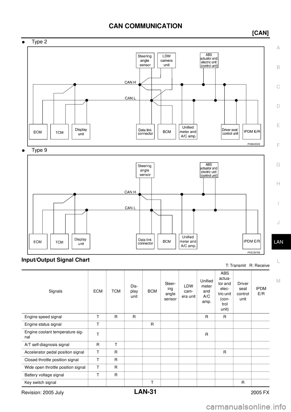
�Ty pe 2
�Ty pe 9
Input/Output Signal Chart
T: Transmit R: Receive
PKIB4202E
PKIC3676E
Signals ECM TCM Dis-
play unit BCM St e e r-
ing
angle
sensor LDW
cam-
era unit Unified
meter and
A/C
amp. ABS
actua-
tor and elec-
tric unit (con-trol
unit) Driver
seat
control unit IPDM
E/R
Engine speed signal T R R R R
Engine status signal T R
Engine coolant temperature sig-
nal TR
A/T self-diagnosis signal R T
Accelerator pedal position signal T R R
Closed throttle position signal T R
Wide open throttle position signal T R
Battery voltage signal T R
Key switch signal T R
Page 3454 of 4731
![INFINITI FX35 2005 Service Manual CAN COMMUNICATION LAN-35
[CAN]
C
D E
F
G H
I
J
L
M A
B
LAN
Revision: 2005 July 2005 FX
Closed throttle position
signal TR R
Wide open throttle posi-
tion signal TR
Battery voltage](/manual-img/42/57020/w960_57020-3453.png "INFINITI FX35 2005 Service Manual CAN COMMUNICATION LAN-35
[CAN]
C
D E
F
G H
I
J
L
M A
B
LAN
Revision: 2005 July 2005 FX
Closed throttle position
signal TR R
Wide open throttle posi-
tion signal TR
Battery voltage")
CAN COMMUNICATION LAN-35
[CAN]
C
D E
F
G H
I
J
L
M A
B
LAN
Revision: 2005 July 2005 FX
Closed throttle position
signal TR R
Wide open throttle posi-
tion signal TR
Battery voltage signal T R
Key switch signal T R
Ignition switch signal T R R
P range signal T R R R
Stop lamp switch signal R T
ABS operation signal R T
TCS operation signal R T
VDC operation signal R T
Fuel consumption moni-
tor signal TR
RT
Turbine revolution signal R T R
Output shaft revolution
signal RT R R
A/C switch signal R T
A/C compressor request
signal T
R
A/C compressor feed-
back signal TR
Blower fan motor switch
signal RT
A/C switch/indicator sig-
nal TR
RT
Cooling fan speed
request signal T
R
Position light request sig-
nal TR R
Low beam request signal T R
Low beam status signal R T
High beam request sig-
nal TR R
High beam status signal R T
Front fog light request
signal TR
Day time running light
request signal TR
Turn LED burnout status
signal RT
Signals ECM TCM
Dis-
play
con-
trol
unit ICC
unit Intelli-
gent Key unit BCM Ste er-
ing
angle
sen- sor LDW
cam- era
unit Uni-
fied
meter and
A/C
amp. ICC
sen-
sor ABS
actu- ator and
elec- tric
unit
(con- trol
unit) Driver
seat
con-
trol
unit IPDM
E/R
Page 3458 of 4731
CAN COMMUNICATION LAN-39
[CAN]
C
D E
F
G H
I
J
L
M A
B
LAN
Revision: 2005 July 2005 FX
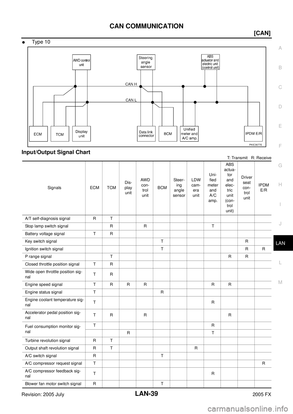
�Type 10
Input/Output Signal Chart
T: Transmit R: Receive
PKIC3677E
Signals ECM TCM Dis-
play unit AWD
con- trol
unit BCM Steer-
ing
angle
sensor LDW
cam- era
unit Uni-
fied
meter and
A/C
amp. ABS
actua- tor
and
elec- tric
unit
(con- trol
unit) Driver
seat
con- trol
unit IPDM
E/R
A/T self-diagnosis signal R T
Stop lamp switch signal R R T
Battery voltage signal T R
Key switch signal T R
Ignition switch signal T R R
P range signal T R R
Closed throttle position signal T R
Wide open throttle position sig-
nal TR
Engine speed signal T R R R R R
Engine status signal T R
Engine coolant temperature sig-
nal TR
Accelerator pedal position sig-
nal TR R R
Fuel consumption monitor sig-
nal TR
RT
Turbine revolution signal R T
Output shaft revolution signal R T R
A/C switch signal R T
A/C compressor request signal T R
A/C compressor feedback sig-
nal TR
Blower fan motor switch signal R T
Page 3462 of 4731
![INFINITI FX35 2005 Service Manual CAN COMMUNICATION LAN-43
[CAN]
C
D E
F
G H
I
J
L
M A
B
LAN
Revision: 2005 July 2005 FX
Battery voltage sig-
nal TR
Key switch signal T R
Ignition switch signal T R R
P range signal T](/manual-img/42/57020/w960_57020-3461.png "INFINITI FX35 2005 Service Manual CAN COMMUNICATION LAN-43
[CAN]
C
D E
F
G H
I
J
L
M A
B
LAN
Revision: 2005 July 2005 FX
Battery voltage sig-
nal TR
Key switch signal T R
Ignition switch signal T R R
P range signal T")
CAN COMMUNICATION LAN-43
[CAN]
C
D E
F
G H
I
J
L
M A
B
LAN
Revision: 2005 July 2005 FX
Battery voltage sig-
nal TR
Key switch signal T R
Ignition switch signal T R R
P range signal T R R R
Closed throttle posi-
tion signal TR R
Wide open throttle
position signal TR
Engine speed signal T R R R R R R
Engine status signal T R
Engine coolant tem-
perature signal TR
Accelerator pedal
position signal TR R R R
Fuel consumption
monitor signal TR
RT
Turbine revolution
signal RT R
Output shaft revolu-
tion signal RT R R
A/C switch signal R T
A/C compressor
request signal T
R
A/C compressor
feedback signal TR
Blower fan motor
switch signal RT
A/C switch/indicator
signal TR
RT
Cooling fan speed
request signal T
R
Position light request
signal RTR R
Low beam request
signal TR
Low beam status sig-
nal R
T
High beam request
signal TR R
High beam status
signal R
T
Front fog light
request signal TR
Signals ECM TCM
Dis-
play
con-
trol
unit AWD
con- trol
unit ICC
unit Intel-
ligent Key unit BCM Steer-
ing
angle
sen- sor LDW
cam- era
unit Uni-
fied
meter and
A/C
amp. ICC
sen-
sor ABS
actu- ator and
elec- tric
unit
(con- trol
unit) Driver
seat
con-
trol
unit IPDM
E/R
Page 3578 of 4731
![INFINITI FX35 2005 Service Manual CAN SYSTEM (TYPE 3) LAN-159
[CAN]
C
D E
F
G H
I
J
L
M A
B
LAN
Revision: 2005 July 2005 FX
2. CHECK HARNESS FOR OPEN CIRCUIT
1. Disconnect ICC unit connector.
2. Check resistance between](/manual-img/42/57020/w960_57020-3577.png "INFINITI FX35 2005 Service Manual CAN SYSTEM (TYPE 3) LAN-159
[CAN]
C
D E
F
G H
I
J
L
M A
B
LAN
Revision: 2005 July 2005 FX
2. CHECK HARNESS FOR OPEN CIRCUIT
1. Disconnect ICC unit connector.
2. Check resistance between")
CAN SYSTEM (TYPE 3) LAN-159
[CAN]
C
D E
F
G H
I
J
L
M A
B
LAN
Revision: 2005 July 2005 FX
2. CHECK HARNESS FOR OPEN CIRCUIT
1. Disconnect ICC unit connector.
2. Check resistance between ICC unit harness connector M88 ter- minals 14 (L) and 5 (R).
OK or NG
OK >> Replace ICC unit.
NG >> Repair harness between ICC unit and harness connec-
tor M82.
Intelligent Key Unit Circuit InspectionAKS00CEN
1. CHECK CONNECTOR
1. Turn ignition switch OFF.
2. Disconnect the battery cable from the negative terminal.
3. Check terminals and connector of Intelligent Key unit for damage, bend and loose connection (unit side and harness side).
OK or NG
OK >> GO TO 2.
NG >> Repair terminal or connector.
2. CHECK HARNESS FOR OPEN CIRCUIT
1. Disconnect Intelligent Key unit connector.
2. Check resistance between Intelligent Key unit harness connec- tor M34 terminals 2 (L) and 3 (R).
OK or NG
OK >> Replace Intelligent Key unit.
NG >> Repair harness between Intelligent Key unit and data link connector.
Data Link Connector Circuit InspectionAKS00CEO
1. CHECK CONNECTOR
1. Turn ignition switch OFF.
2. Disconnect the battery cable from the negative terminal.
3. Check data link connector and terminals for damage, bend and loose connection (connector side and har- ness side).
OK or NG
OK >> GO TO 2.
NG >> Repair terminal or connector. 14 (L) - 5 (R) : Approx. 54 - 66
Ω
SKIA6886E
2 (L) - 3 (R) : Approx. 54 - 66Ω
SKIA6887E