2005 HYUNDAI XG350 fuel
[x] Cancel search: fuelPage 201 of 247

6
DO-IT-YOURSELF MAINTENANCE
21
HEADLIGHT AIMING ADJUSTMENT
!
!
G290A03L-AATHID Type (If Installed)Before performing aiming adjustment, make
sure of the following.
G290A02L-A
Vertical
aiming1. Keep all tires inflated to the correct pressure.
2. Place the vehicle on level ground and press
the front bumper & rear bumper down sev-
eral times. Place vehicle at a distance of 118
in. (3m) from the test wall.
3. See that the vehicle is unloaded (except for
full levels of coolant, engine oil and fuel, and
spare tire, jack, and tools). Have the driver
or equivalent weight placed in driver's seat.
4. Clean the head light lenses and turn on the
headlights (Low beam).
5. Open the hood.
6. Draw the vertical line (through the center of
each headlight) and the horizontal line
(through the center of each headlight) on the
aiming screen.
And then, draw a parallel line at 0.8in.(21mm.)
under the horizontal line.
7. Adjust each cut-off line of the low beam to the
parallel line with a phillips screwdriver -
VERTICAL AIMING
WARNING:
If you need headlight aiming adjustment,
have your vehicle inspected by your Hyundai
Dealer.
Don't attempt to replace or inspect the HID
headlight bulb to prevent danger of an
electric shock.General Type
WARNING:
Horizontal aiming should be adjusted by an
authorized Hyundai Dealer.
G290B02L-AATAdjustment After Headlight Assembly
ReplacementIf the vehicle has had front body repair and the
headlight assembly has been replaced, the
headlight aiming should be checked using an
aiming screen as shown in the illustration. Turn
on the headlight switch. (Low Beam Position)
1. Adjust headlights so that main axis of light is
parallel to center line of the body and is
aligned with point "P" shown in the illustration.
2. Dotted lines in the illustration show center of
headlights.
G290B01L-A
LW
H
HCut-off line
Ground
line
"P" Horizontal lineVertical line
0.83 in. (21 mm)
xgflhma-6.p656/16/04, 2:59 PM 21
Page 213 of 247

6
DO-IT-YOURSELF MAINTENANCE
33
DESCRIPTION
FUEL PUMP
HEAD LIGHT(Lo-LH)
ABS
INJECTOR
A/C COMPRESSOR
A/T
MAIN
IGNITION COIL
OXYGEN SENSOR
EGR
HORN
HEAD LIGHT(HI)
HEAD LIGHT(Lo-RH)
DRL
FOG LIGHT
DIODE 1FUSERATING
20A
15A
10A
10A
10A
20A
30A
20A
15A
15A
15A
15A
15A
15A
15AFuel pump relay
Head light relay (Low-LH)
ABS controls, Cruise control module, ETS control module
Limp home valve, ETS controls, Injector
A/C relay
A/T control relay, TCM, Engine control relay
MFI controls
Ignition coil, A/T pulse generator, ECM, Ignition failure sensor, E/TCM
ETS relay, MFI controls
A/C relay, MFI controls, EGR solenoid
Horn relay
Head light relay (High)
HID head light relay
DRL control module, Siren
Fog light relay
-
PROTECTED COMPONENTS
xgflhma-6.p656/16/04, 2:59 PM 33
Page 216 of 247

6
DO-IT-YOURSELF MAINTENANCE
36
FUSERATING
10A
10A
15A
10A
20A
10A
10A
10A
10A
10A
10A
10A
10APROTECTED COMPONENTS
Door warning & Ignition key illumination, Courtesy lights
Instrument cluster
SRS controls
Automatic transaxle controls, Back-up light switch,
Vehicle speed sensor
Fuel filler door & Trunk lid opener, Driver (Assister) door module
Multipurpose check connector, Audio, lmmobiilizer controls,
Trip computers, Digital clock, Blower & A/C controls, Instrument cluster
Left (Right) inside lights, (HID) Head lights, Fog light relay,
Right HID turn signal light, Right rear combination light
Stop light failure relay
Immobilizer controls, TCS switch, Trip computers, Instrument cluster
ETACM, Hazard switch, Auto light sensor
Antenna, Blower & A/C controls,
Left (Right) outside mirror motor & Folding motor
(HID) Head lights, Front (Rear) cigarette lighters,
Left (Right) license lights, Left HID Turn signal light,
Left rear combination light
Burglar alarm relay, Transaxle range switch, Start relay, ETS controls DESCRIPTION
ROOM LP
A/BAG IND
A/BAG
B/UP
T/LID
D/CLOCK
RH TAIL
SPARE
CLUSTER
T/SIG
RR HTD IND
LH TAIL
START
xgflhma-6.p656/16/04, 2:59 PM 36
Page 218 of 247

7
EMISSION CONTROL SYSTEMS2
EMISSION CONTROL SYSTEMH010A02L-AATYour Hyundai is equipped with an emission
control system to meet all requirements of the
U.S. Environmental Protection Agency or Cali-
fornia Air Resources Board.
There are three emission control systems which
are as follows.
(1) Crankcase emission control system
(2) Evaporative emission control system
(3) Exhaust emission control system
In order to assure the proper function of the
emission control systems, it is recommended
that you have your car inspected and main-
tained by an authorized Hyundai dealer in ac-
cordance with the maintenance schedule in this
manual.
Caution for the Inspection and Maintenance
Test (3.5 V6 Vehicle with Traction Control
System)
After dynamometer testing is completed,
erase the ABS/TCS DTC(Diagnotic Trouble
Code) with a GST (Generic Scan Tool) or Hi-
Scan Pro.
H010B01A-AAT1. Crankcase Emission Control
SystemThe positive crankcase ventilation system is
employed to prevent air pollution caused by
blow-by gases being emitted from the crank-
case. This system supplies filtered air to the
crankcase through the air intake hose. Inside
the crankcase, the fresh air mixes with blow-by
gases, which then pass through the PCV valve
and into the induction system.
H010C01S-AAT2. Evaporative Emission Control (Includ-
ing ORVR: Onboard Refueling Vapor
Recovery) SystemThe Evaporative Emission Control System is
designed to prevent fuel vapors from escaping
into the atmosphere.
(The ORVR system is designed to allow the
vapors from the fuel tank to be loaded into
a canister while refueling at the gas station,
preventing the escape of fuel vapors into
the atmosphere.)CanisterFuel vapors generated inside the fuel tank are
absorbed and stored in the onboard canister.
When the engine is running, the fuel vapors
absorbed in the canister are drawn into the
induction system through the purge control
solenoid valve.Purge Control Solenoid Valve (PCSV)The purge control solenoid valve is controlled
by the Engine Control Module (ECM); when the
engine coolant temperature is low during idling,
the PCSV closes so that evaporated fuel is not
taken into the engine. After the engine warms-
up during ordinary driving, the PCSV opens to
introduce evaporated fuel to the engine.
xgflhma-7.p656/16/04, 2:57 PM 2
Page 219 of 247

7
EMISSION CONTROL SYSTEMS
3
CATALYTIC CONVERTER
!
WARNING:
o Use unleaded fuel only.
o Maintain the engine in good operating
condition. Extremely high catalytic con-
verter temperatures can result from im-
proper operation of the electrical, igni-
tion or multiport electronic fuel injec-
tion.
o If your engine stalls, pings, knocks, or is
hard to start, have your Hyundai dealer
inspect and repair the problem as soon
as possible.
o Avoid driving with a very low fuel level.
Running out of gasoline may cause the
engine to misfire and result in damage to
the catalytic converter.
o Avoid idling the engine for periods
longer than 10 minutes.
o The vehicle should not be pushed or
pulled to get started. This may cause the
catalytic converter to overheat and cre-
ate a fire hazard.
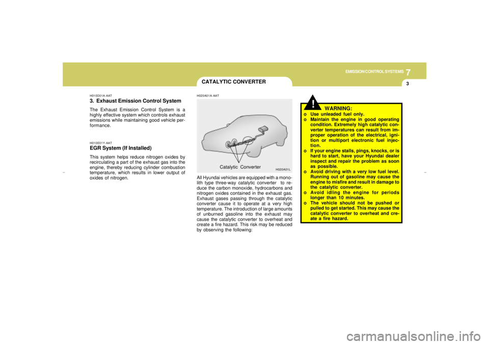
H020A01A-AATAll Hyundai vehicles are equipped with a mono-
lith type three-way catalytic converter to re-
duce the carbon monoxide, hydrocarbons and
nitrogen oxides contained in the exhaust gas.
Exhaust gases passing through the catalytic
converter cause it to operate at a very high
temperature. The introduction of large amounts
of unburned gasoline into the exhaust may
cause the catalytic converter to overheat and
create a fire hazard. This risk may be reduced
by observing the following:Catalytic Converter
H020A01L
H010E01Y-AATEGR System (If Installed)This system helps reduce nitrogen oxides by
recirculating a part of the exhaust gas into the
engine, thereby reducing cylinder combustion
temperature, which results in lower output of
oxides of nitrogen.H010D01A-AAT3. Exhaust Emission Control SystemThe Exhaust Emission Control System is a
highly effective system which controls exhaust
emissions while maintaining good vehicle per-
formance.
xgflhma-7.p656/16/04, 2:57 PM 3
Page 224 of 247

8
CONSUMER INFORMATION & REPORTING SAFETY DEFECTS4
!
RECOMMENDED INFLATION
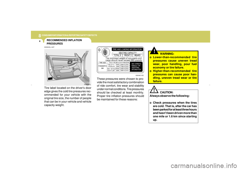
PRESSURESI030A03L-AATTire label located on the driver's door
edge gives the cold tire pressures rec-
ommended for your vehicle with the
original tire size, the number of people
that can be in your vehicle and vehicle
capacity weight.
I030A01L
These pressures were chosen to pro-
vide the most satisfactory combination
of ride comfort, tire wear and stability
under normal conditions. Tire pressures
should be checked at least monthly.
Proper tire inflation pressures should
be maintained for these reasons:
!
CAUTION:
Always observe the following:
o Check pressures when the tires
are cold. That is, after the car has
been parked for at least three hours
and hasn't been driven more than
one mile or 1.6 km since starting
up.WARNING:
o Lower-than-recommended tire
pressures cause uneven tread
wear, poor handling, pour fuel
economy or tire failure.
o Higher-than-recommended tire
pressures can cause poor han-
dling, uneven tread wear or tire
failure.
I030A01XG
xgflhma-8.p656/16/04, 2:57 PM 4
Page 228 of 247

8
CONSUMER INFORMATION & REPORTING SAFETY DEFECTS8
Intended Outboard Sidewall: The side
of an asymmetrical tire, that must al-
ways face outward when mounted on a
vehicle.
Kilopascal (kPa): The metric unit for
air pressure.
Load Index: An assigned number rang-
ing from 1 to 279 that corresponds to
the load carrying capacity of a tire.
Maximum Inflation Pressure: The
maximum air pressure to which a cold
tire may be inflated. The maximum air
pressure is molded onto the sidewall.
Maximum Load Rating: The load rat-
ing for a tire at the maximum permis-
sible inflation pressure for that tire.
Maximum Loaded Vehicle Weight:
The sum of curb weight; accessory
weight; vehicle capacity weight; and
production options weight.
Normal Occupant Weight: The num-
ber of occupants a vehicle is designed
to seat multiplied by 150 pounds (68
kg).Occupant Distribution: Designated
seating positions.
Outward Facing Sidewall: The side of
a asymmetrical tire that has a particular
side that faces outward when mounted
on a vehicle. The side of the tire that
contains a whitewall, bears white letter-
ing or bears manufacturer, brand and or
model name molding that is higher or
deeper than the same moldings on the
other sidewall of the tire.
Passenger (P-Metric) Tire: A tire used
on passenger cars and some light duty
trucks and multipurpose vehicles.
Recommended Inflation Pressure:
Vehicle manufacturer's recommended
tire inflation pressure and shown on the
tire placard.
Radial Ply tire: A pneumatic tire in
which the ply cords that extend to the
beads are laid at 90 degrees to the
centerline of the tread.
Rim: A metal support for a tire and upon
which the tire beads are seated. Cold Tire Pressure: The amount of air
pressure in a tire, measured in pounds
per square inch (psi) or kilopascals
(kPa) before a tire has built up heat from
driving.
Curb Weight: This means the weight of
a motor vehicle with standard and op-
tional equipment including the maxi-
mum capacity of fuel, oil and coolant,
but without passengers and cargo.
DOT Markings: A code molded into the
sidewall of a tire signifying that the tire
is in compliance with the U.S. Depart-
ment of Transportation motor vehicle
safety standards. The DOT code in-
cludes the Tire Identification Number
(TIN), an alphanumeric designator which
can also identify the tire manufacturer,
production plant, brand and date of
production.
GVWR: Gross Vehicle Weight Rating
GAWR FRT: Gross Axle Weight Rating
for the front Axle.
GAWR RR: Gross Axle Weight Rating
for the rear axle.
xgflhma-8.p656/16/04, 2:57 PM 8
Page 238 of 247

9
VEHICLE SPECIFICATIONS2
J060A01L-AATFUEL SYSTEM
J050A01L-GATBRAKEJ040A01L-AATELECTRICAL
J020A01L-AATPOWER STEERINGJ010A02L-AATMEASUREMENT
191.8 (4875)
70.86 (1800)
55.9 (1420)
108.2 (2750)
60.6 (1540)
60.23 (1530) Overall length
Overall width
Overall height
Wheel base
Wheel tread
Front
Rear
Type
Wheel free play
Rack stroke
Oil pump typeRack and pinion
0 ~ 1.18 in (0 ~ 30 mm.)
5.74 in (146 mm.)
Vane type
Battery
AlternatorMF 68AH (MF)
120A (13.5V)
Dual hydraulic with brake booster
Ventilated disc
Solid disc
Cable operated on rear wheel Type
Front brake type
Rear brake type
Parking brake
18.5 US.gal (15.4 Imp.gal, 70 Liter)
Fuel tank capacity
J030A03L-AATTIRE
Tire pressure
Tire
Standardpsi (kpa)
Size
P205/60 R16 94H in. (mm)
Front
Rear
33 (230)
30 (210)
xgflhma-9.p656/16/04, 2:56 PM 2