2005 Hyundai Terracan instrument cluster
[x] Cancel search: instrument clusterPage 115 of 539
1
FEATURES OF YOUR HYUNDAI
101
NOTE: The "CRUISE" indicator light in the instrument cluster will illuminate after you have set the vehicle speedat the desired speed (Gasoline En- gine Only).
4. Remove your foot from the accel-
erator pedal and the desired speed will automatically be maintained.
5. To increase speed, depress the accelerator pedal enough for thevehicle to exceed the preset speed.When you remove your foot from the accelerator pedal, the vehicle will return to the speed you haveset.
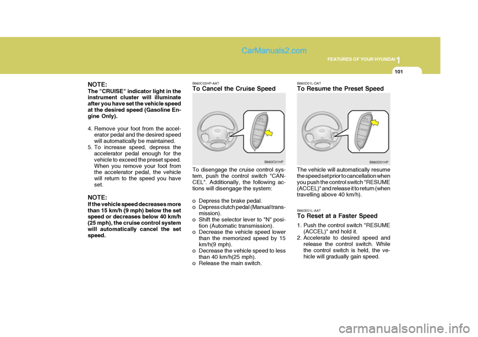
NOTE: If the vehicle speed decreases more than 15 km/h (9 mph) below the set speed or decreases below 40 km/h (25 mph), the cruise control systemwill automatically cancel the set speed. B660C02HP-AAT To Cancel the Cruise Speed To disengage the cruise control sys- tem, push the control switch "CAN- CEL". Additionally, the following ac-tions will disengage the system:
o Depress the brake pedal.
o Depress clutch pedal (Manual trans-
mission).
o Shift the selector lever to "N" posi- tion (Automatic transmission).
o Decrease the vehicle speed lower
than the memorized speed by 15km/h(9 mph).
o Decrease the vehicle speed to less
than 40 km/h(25 mph).
o Release the main switch. B660D01L-DAT To Resume the Preset Speed
The vehicle will automatically resume the speed set prior to cancellation when you push the control switch "RESUME(ACCEL)" and release it to return (when travelling above 40 km/h).
B660C01HP
B660D01HP
B660E01L-AAT To Reset at a Faster Speed
1. Push the control switch "RESUME (ACCEL)" and hold it.
2. Accelerate to desired speed and release the control switch. While the control switch is held, the ve-hicle will gradually gain speed.
Page 269 of 539

6
DO-IT-YOURSELF MAINTENANCE
47
AMPERAGES(A) 50A 30A 40A 40A 30A 40A 20A-
20A 10A 15A
NO. 1
NO. 2
NO. 3
NO. 4
NO. 5
NO. 6
NO. 7
NO. 8
NO. 9
DESCRIPTION
CIRCUIT PROTECTED
Power Connector(A,B), Engine Compartment Fuse and Relay Box #2
(Fuse 28,29), Inner Panel Fuse Box(Fuse 6,7,8, 9)
Start Relay, Ignition Switch
Condenser Fan Relay,
Engine Compartment Fuse and Relay Box #2(Fuse 14,15)ABS Control Module
Power Window Relay
Tail Lamp Relay,
Engine Compartment Fuse and Relay Box #2(Fuse 11,12)ABS Control Module-
Fuel Pump Relay, ECM, Ignition Failure Sensor
A/CON, TCM, ETACM, Data Link Connector, Siren,
Immobilizer Control Module
Interior Lamp, Map Lamp, Audio, Instrument Cluster,
Front Door Edge warning Lamp
FUSIBLE LINK
NO. 30
NO. 31
Page 270 of 539

6 DO-IT-YOURSELF MAINTENANCE
48
NO.1 2 34 5 67 8 9
10 11 1213 14 1516 17 1819 20 2122 23 2425 26 2728 AMPERAGES(A)
30A 10A 15A 20A10A15A30A20A 10A 10A20A10A- -
10A 10A -
10A10A10A10A 10A 10A
-
10A15A15A 10A CIRCUIT PROTECTED
Defogger Relay
Hazard Relay, Hazard Switch Stop Lamp Switch
TOD, EST Control Module - Sunroof Controller
Blower Relay
Power Door Locks
Rear Fog Lamp Relay
Audio, Map Lamp
Cigarette Lighter, Power Outlet relay, ACC Socket
Power Outside Mirror Switch- - A/C Switch
Left/Right Outside Mirror & Defogger -
TCM, ECM(COVEC-F), TCCS(TOD, EST), Immobilizer
Back-up Lamp Switch, Inside Rearview Mirror, Transmission Range Switch Hazard Switch
Instrument Cluster, ETACM, Vehicle Speed Sensor, DRL Control ModuleAirbag Airbag Indicator -
Blower & A/C, ETACM, Defogger Relay
Seat Warmer
Sunroof, Rear Wiper & Washer, Cruise Switch, Rear Intermittent Wiper Relay
Start Relay, Theft-Alarm Relay
G200E01HP-GAT Inner Panel NOTE: Not all fuse panel descriptions in this manual may be applicable to your vehicle. It is accurate at the time of printing. When you inspect the fuse box on your vehicle, refer to the fuse box label. G200D01HP
Page 291 of 539
10INDEX
4
G General Checks .......................................................... 6-5
Glove Box ................................................................. 1-86
HHazard Warning Syst em ........................................... 1-78
Headlight Aiming Adjustment ....................................6-40
Headlight Leveling Device Syst em ...........................1-99
Heating and Ventilation ................. ......................... . 1-104
Air flow control ......................................... 1-105, 1-116 Temperature control ............................................. 1-107
High-Mounted Rear Stop Light ................................. 1-95
Hood Release ........................................................... 1-96
Horn .......................................................................... 1-98
IIgnition Sw itch ............................................................. 2-3
Immobilizer S ystem ..................................................... 1-5
Limp Home Procedures ................................... 1-7, 1-9
Key ................................................................... 1-5, 1-8
Indicator and Warning Lights.................................... 1-58
Instrument Cluster and Indicator Li ghts................... 1-54
Instrument Panel Light Control (Rheo stat)............... 1-79
Interior Light .............................................................. 1-85
Intermittent Wiper ..................................................... 1-77
J Jump Starting .............................................................. 3-3 K
Key .............................................................................. 1-4
If you lose your keys ............................................. 3-17
Positions ................................................................... 2-4
L Limited-Slip D ifferential ............................................. 2-22
Luggage Compartment
Cargo Security Scr een ........................................... 1-94
Light ....................................................................... 1-93
Net .......................................................................... 1-93
M Maintenance Intervals Explanation of scheduled maintenance items ......... 5-9
Maintenance under severe usage conditions .......... 5-8 Scheduled maintenance ........................................... 5-4
Service requ irements............................................... 5-2
Mirrors Day/night inside rearview .......................................1-91
Outside rearview .................................................... 1-88
Multimet er ................................................................. 1-69
Altimeter ................................................................. 1-70
Barometer .............................................................. 1-72
Digital Clock ........................................................... 1-72
Electrical azi muth compass ................................... 1-70
Relative altimeter ................................................... 1-71
Page 304 of 539

CAUTION:
When installing a container of liquid air freshener inside the vehicle, do not place it near the instrument cluster nor on the instrument panel pad surface. If there is any leakage from theair freshener onto these areas (Instrument cluster, instrument panel pad or air ventilator), it may damage these parts. If the liquid from air freshener does leak onto these areas, wash them with water immediately.!
1. Passenger's Airbag
2. Glove Box
3. Heating/Air Conditioning Control Panel
4. Headlight Leveling Switch
5. Cruise Control Main Switch(Not all models)
6. Hazard Warning Switch
7. Panel Brightness Control Knob (Rheostat Switch)
8. Windscreen Wiper/Washer Switch
9. Rear Fog Light Switch
10. Horn and Driver's Airbag
11. Instrument Cluster
12. Multi-Function Light Switch/Front Fog Light Switch
13. Rear Ashtray
14. Rear Drink Holder
15. Rear Power Outlet
16. Front Drink Holder
17. Parking Brake
18. Transfer Shift Knob
19. Front Power Outlet
20. Seat Warmer Switch (Not all models)
21. Shift Lever
22. Coin Holder
23. Front Ashtray/Cigar Lighter
24. Steering Wheel Tilt Lever
25. Cruise Control Switch (Not all models)
26. Remote Fuel-Filler Lid Release Lever
27. Multi Box
28. Bonnet Release Lever
Page 305 of 539
YOUR VEHICLE AT A GLANCE
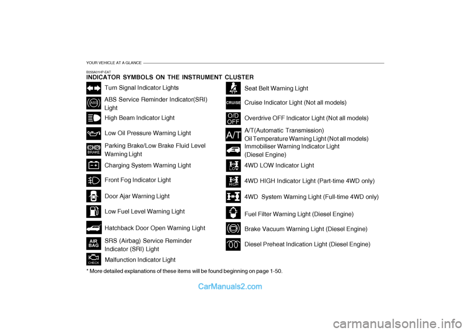
B255A01HP-EAT INDICATOR SYMBOLS ON THE INSTRUMENT CLUSTER
Turn Signal Indicator Lights
ABS Service Reminder Indicator(SRI) LightHigh Beam Indicator Light Low Oil Pressure Warning Light Parking Brake/Low Brake Fluid Level Warning Light Charging System Warning Light
Hatchback Door Open Warning Light
Door Ajar Warning Light Low Fuel Level Warning Light
Front Fog Indicator Light
Overdrive OFF Indicator Light (Not all models)
Immobiliser Warning Indicator Light (Diesel Engine)
Seat Belt Warning Light Cruise Indicator Light (Not all models)
Malfunction Indicator Light
A/T(Automatic Transmission) Oil Temperature Warning Light (Not all models)
4WD LOW Indicator Light 4WD HIGH Indicator Light (Part-time 4WD only)
4WD System Warning Light (Full-time 4WD only)
Fuel Filter Warning Light (Diesel Engine)
Brake Vacuum Warning Light (Diesel Engine)
Diesel Preheat Indication Light (Diesel Engine)
* More detailed explanations of these items will be found beginning on page 1-50.SRS (Airbag) Service Reminder Indicator (SRI) Light
Page 306 of 539
Fuel Recommendations ............................................... 1-2
Running In Your Hyundai .............................................. 1-4
Immobiliser System ...................................................... 1-5
Door Locks ................................................................... 1-9Theft-Alarm System ..................................................... 1-11
Power Windows ........................................................... 1-14
Seats ........................................................................... 1-16
Seat Belts .................................................................... 1-25
Child Restraint System ................................................ 1-31
Supplemental Restraint (AIRBAG) System .................1-40
Instrument Cluster and Indicator Lights .......................1-46
Warning and Indicator Lights....................................... 1-50
Multi-Function Switch .................................................. 1-60
Windscreen Wiper/Washer Switch ..............................1-63
Sunroof ........................................................................ 1-70
Mirror ........................................................................... 1-75
Bonnet Release ........................................................... 1-83
Cruise Co ntrol.............................................................. 1-86
Heating and Cooling Control .......... ..............................1-89
Stereo Sound System ............................................... 1-105
Antenna ..................................................................... 1-107
CONTROLS AND EQUIPMENT
1
1
Page 347 of 539
1CONTROLS AND EQUIPMENT
42
The SRS service reminder indicator (SRI) on the instrument panel will blinkfor about 6 seconds after the ignition key is turned to the "ON" position or after the engine is started, after whichthe SRI should go out.
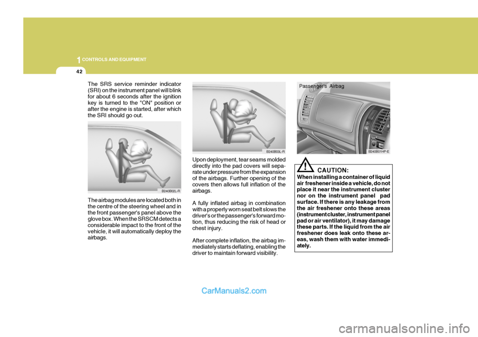
Upon deployment, tear seams moldeddirectly into the pad covers will sepa- rate under pressure from the expansion of the airbags. Further opening of the covers then allows full inflation of the airbags. A fully inflated airbag in combination with a properly worn seat belt slows thedriver's or the passenger's forward mo-
tion, thus reducing the risk of head or chest injury. After complete inflation, the airbag im- mediately starts deflating, enabling thedriver to maintain forward visibility.
The airbag modules are located both inthe centre of the steering wheel and inthe front passenger's panel above the glove box. When the SRSCM detects a considerable impact to the front of thevehicle, it will automatically deploy the airbags.
B240B02L-R
B240B03L-R
!
CAUTION:
When installing a container of liquid air freshener inside a vehicle, do not place it near the instrument cluster nor on the instrument panel padsurface. If there is any leakage from the air freshener onto these areas (instrument cluster, instrument panelpad or air ventilator), it may damage these parts. If the liquid from the air freshener does leak onto these ar-eas, wash them with water immedi- ately.
B240B01HP-E
Passenger's Airbag