Page 260 of 539

6 DO-IT-YOURSELF MAINTENANCE
38
!
G300B02HP-GAT
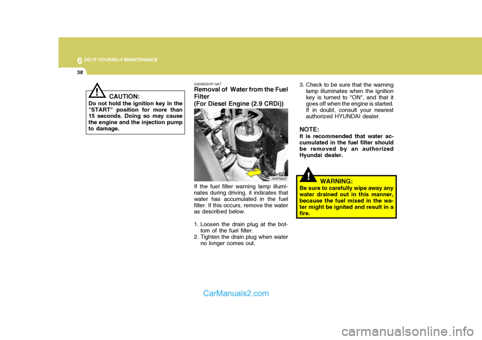
Removal of Water from the Fuel Filter (For Diesel Engine (2.9 CRDi))
If the fuel filter warning lamp illumi-
nates during driving, it indicates that water has accumulated in the fuelfilter. If this occurs, remove the water as described below.
1. Loosen the drain plug at the bot-
tom of the fuel filter.
2. Tighten the drain plug when water
no longer comes out. 3. Check to be sure that the warning
lamp illuminates when the ignition key is turned to "ON", and that it goes off when the engine is started. If in doubt, consult your nearest authorized HYUNDAI dealer.
NOTE: It is recommended that water ac-
cumulated in the fuel filter should be removed by an authorizedHyundai dealer.
WARNING:
Be sure to carefully wipe away any
water drained out in this manner,because the fuel mixed in the wa- ter might be ignited and result in a fire.
HHP5047
!
CAUTION:
Do not hold the ignition key in the
"START" position for more than 15 seconds. Doing so may cause the engine and the injection pumpto damage.
Page 261 of 539
6
DO-IT-YOURSELF MAINTENANCE
39REPLACING HEADLIGHT BULBS
G260A02A-GAT Before attempting to replace a head- light bulb, be sure the switch is turned to the "OFF" position. The next paragraph shows how to reach the headlight bulbs so they may be changed. Be sure to replacethe burned-out bulb with one of the same number and wattage rating.
CAUTION:
Keep the lamps out of contact with
petroleum product, such as oil, gasoline, etc.
! G270A01B-GAT
Headlight Bulb
1. Allow the bulb to cool. Wear eye
protection.
2. Open the engine hood.
3. Always grasp the bulb by its plas- tic base, avoid touching the glass.
4. Using a spanner, remove the head- light assembly mounting bolts.
5. Disconnect the power cord from the bulb base in the back of the headlight.
G270A01HP7. Disconnect the connector from the
bulb base in the back of the head- light.
G270A02HP
6. Turn the plastic cover counter- clockwise and remove it. 8. Push the bulb spring to remove
the headlight bulb.
Page 263 of 539

6
DO-IT-YOURSELF MAINTENANCE
41
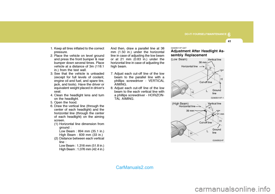
1. Keep all tires inflated to the correct
pressure.
2. Place the vehicle on level ground and press the front bumper & rear bumper down several times. Placevehicle at a distance of 3m (118.1 in.) from the test wall.
3. See that the vehicle is unloaded (except for full levels of coolant, engine oil and fuel, and spare tire,jack, and tools). Have the driver or equivalent weight placed in driver's seat.
4. Clean the headlight lens and turn on the headlight.
5. Open the hood.
6. Draw the vertical line (through the center of each headlight) and thehorizontal line (through the center of each headlight) on the aiming screen.
(1) Horizontal line dimension from
ground : Low Beam : 894 mm (35.1 in.) High Beam : 839 mm (33 in.)
(2) Distance between each vertical line : Low Beam : 1,316 mm (51.8 in.) High Beam : 1,076 mm (42.4 in.) And then, draw a parallel line at 38
mm (1.50 in.) under the horizontalline in case of adjusting the low beam or at 21 mm (0.83 in.) under the horizontal line in case of adjusting thehigh beam.
7. Adjust each cut-off line of the low beam to the parallel line with a phillips screwdriver - VERTICALAIMING.
8. Adjust each cut-off line of the low beam to the each vertical line witha phillips screwdriver - HORIZON- TAL AIMING. G290B01HP-GAT Adjustment After Headlight As- sembly Replacement
G290B02HP
LW
H Cut-off line
"P"
Vertical line
Horizontal line
Ground line
21 mm39 mm
(High Beam)
H
G290B01HP-1
LW
"P"
38 mm
H
H
(Low Beam)
Vertical line
Ground line
Cut-off line
Horizontal line
Page 266 of 539
6 DO-IT-YOURSELF MAINTENANCE
44
NO.1
NO. 2
NO. 3
NO.4
NO.5
NO. 6
NO. 7
NO. 8
NO. 9
NO. 10
NO. 11
NO. 12
DESCRIPTION
G200C01HP-GAT Engine Compartment (#1)
G200C01HP
NOTE: Not all fuse panel descriptions in this manual may be applicable to your vehicle. It is accurate at the time of printing. When you inspect the fuse box on your vehicle, refer to the fuse box label. AMPERAGES(A)
100A
120A (DIESEL)
140A (GASOLINE)
50A 30A- -
20A 10A 15A -
10A10A CIRCUIT PROTECTED
Glow Relay (COVEC-F/EGR), Air Heater Relay (2.9 CRDi)
Engine Compartment Fuse & Relay Box #2,Generator
Inner Panel Fuse Box (Fuse 1,2,3,4,5),
Engine Compartment Fuse & Relay Box #1 (Fuse 8,9),
Fuel Heater Control Module (COVEC-F/EGR)
Generator, Ignition Switch--
Engine Control Relay (Diesel Engine), Main Control Relay(Gasoline Engine)
Horn Relay
Front Fog Lamp Relay-ECM (Diesel Engine), EGR Control ModuleECM (2.9 CRDi)
FUSIBLE LINK
FUSE
FUSE PANEL DESCRIPTION
Gasoline Engine Diesel Engine
Page 267 of 539
6
DO-IT-YOURSELF MAINTENANCE
45
NOTE: Not all fuse panel descriptions in this manual may be applicable to your vehicle. It is accurate at the time of printing. When you inspect the fuse box on your vehicle, refer to the fuse box label.
G200D01HP-GAT
Engine Compartment (#2)
G200C02HP
Page 268 of 539
6 DO-IT-YOURSELF MAINTENANCE
46
AMPERAGES(A)15A 15A15A-
10A 10A
-
15A 15A15A15A 10A 10A10A 10A 10A 10A15A25A20A
NO. 10
NO. 11
NO. 12
NO. 13
NO. 14
NO. 15
NO. 16
NO. 17
NO. 18
NO. 19
NO. 20
NO. 21
NO. 22
NO. 23
NO. 24
NO. 25
NO. 26
NO. 27
NO. 28
NO. 29
DESCRIPTION
CIRCUIT PROTECTED
Fuel Heater and Sensor(2.9 CRDi)
Headlamp(Low beam)Headlamp(High beam) -
A/C Compressor Relay, Triple Switch
TCI Fan Relay(COVEC-F/EGR)--ECM(Diesel Engine)ECM(Diesel Engine)
ECM(2.9 CRDi), Air Heater Relay(2.9 CRDi), EGR Solenoid(2.9 CRDi)
Illuminations, Combination Lamp
License Lamp, Combination Lamp
ABS Control Module, ABS Relay, EBD Relay
ECM(Diesel Engine), Headlamp Relay, Condenser Fan Relay
(Gasoline/COVEC-F), EGR Solenoid(COVEC-F)ABS Control Module
Cruise Control Module
Front Wiper and Washer
Power Seat Switch
Power Outlet Relay
FUSE
Page 269 of 539
6
DO-IT-YOURSELF MAINTENANCE
47
AMPERAGES(A) 50A 30A 40A 40A 30A 40A 20A-
20A 10A 15A
NO. 1
NO. 2
NO. 3
NO. 4
NO. 5
NO. 6
NO. 7
NO. 8
NO. 9
DESCRIPTION
CIRCUIT PROTECTED
Power Connector(A,B), Engine Compartment Fuse and Relay Box #2
(Fuse 28,29), Inner Panel Fuse Box(Fuse 6,7,8, 9)
Start Relay, Ignition Switch
Condenser Fan Relay,
Engine Compartment Fuse and Relay Box #2(Fuse 14,15)ABS Control Module
Power Window Relay
Tail Lamp Relay,
Engine Compartment Fuse and Relay Box #2(Fuse 11,12)ABS Control Module-
Fuel Pump Relay, ECM, Ignition Failure Sensor
A/CON, TCM, ETACM, Data Link Connector, Siren,
Immobilizer Control Module
Interior Lamp, Map Lamp, Audio, Instrument Cluster,
Front Door Edge warning Lamp
FUSIBLE LINK
NO. 30
NO. 31
Page 272 of 539

7EMISSION CONTROL SYSTEMS
2EMISSION CONTROL SYSTEMS
H010A01A-GAT
(If Installed)
Your Hyundai is equipped with an
emission control system to meet all requirements of the Emission prohibi- tion rules of your province.
There are three emission control sys-
tems which are as follows.
(1) Crankcase emission control sys- tem (For a Gasoline Engine)
(2) Evaporative emission control sys- tem (For a Gasoline Engine)
(3) Exhaust emission control system
In order to assure the proper function
of the emission control systems, it is recommended that you have your carinspected and maintained by an au- thorized Hyundai dealer in accordance with the maintenance schedule in thismanual. H010B01A-AAT
1. Crankcase Emission Control
System ; For a Gasoline Engine
The positive crankcase ventilation
system is employed to prevent air pollution caused by blow-by gasesbeing emitted from the crankcase. This system supplies fresh filtered air to the crankcase through the air in-take hose. Inside the crankcase, which the fresh air mixes with blow-by gases, which then pass through the PCVvalve into the induction system.
H010C02Y-GAT
2. Evaporative Emission
Control System ; For a Gasoline Engine
The Evaporative Emission Control
System is designed to prevent fuel vapors from escaping into the atmo- sphere. Canister
While the engine is inoperative, fuel
vapors generated inside the fuel tankare absorbed and stored in the canis- ter. When the engine is running, thefuel vapors absorbed in the canister are drawn into the induction system through the purge control solenoidvalve. Purge Control Solenoid Valve
The purge control solenoid valve is
controlled by the ECM; when the en- gine coolant temperature is low, and during idling, it closes, so that evapo- rated fuel is not taken into the surgetank. After engine warm-up, during ordinary driving, it opens so as to introduce evaporated fuel to the surgetank. H010D01A-AAT
3. Exhaust Emission Control
System
The Exhaust Emission Control Sys- tem is a highly effective system whichcontrols exhaust emissions while maintaining good vehicle performance.