Page 508 of 539

6
OWNER MAINTENANCE
31
!
!
3. Check to be sure that the warning
lamp illuminates when the ignition key is turned to "ON", and that it goes off when the engine is started. If in doubt, consult your nearest authorised HYUNDAI dealer.
NOTE: It is recommended that water accu- mulated in the fuel filter should be removed by an authorised Hyundai dealer.
WARNING:
Be sure to carefully wipe away anywater drained out in this manner, because the fuel mixed in the water might be ignited and resultin a fire. Before attempting to replace a head-
light bulb, be sure the switch is turned to the "OFF" position.
The next paragraph shows how to
reach the headlight bulbs so they may be changed. Be sure to replacethe burned-out bulb with one of the same number and wattage rating.
Ensure that the replacement bulb has
the same cap configuration and watt-age as the original.
See page 6-35 for the wattage descrip-
tions.
CAUTION:
Keep the lamps out of contact with
petroleum product, such as oil, petrol, etc.
REPLACING HEADLIGHT BULBS
G260A01HP-EAT
G270A01B-EAT Headlight Bulb
1. Allow the bulb to cool. Wear eye
protection.
2. Open the engine bonnet.
3. Always grasp the bulb by its plas- tic base, avoid touching the glass.
4. Using a spanner, remove the head- light assembly mounting bolts.
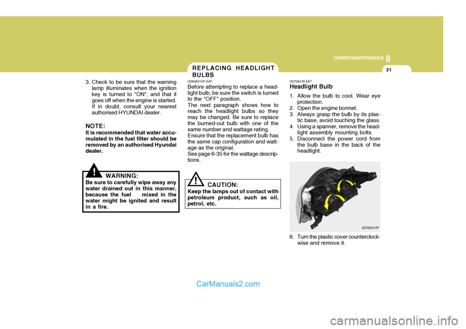
5. Disconnect the power cord from the bulb base in the back of the headlight.
G270A01HP
6. Turn the plastic cover counterclock- wise and remove it.
Page 513 of 539
6 OWNER MAINTENANCE
36
NO.1
NO. 2
NO. 3
NO.4
NO.5
NO. 6
NO. 7
NO. 8
NO. 9
NO. 10
NO. 11
NO. 12
DESCRIPTION
G200C01HP-EAT Engine Compartment (#1)
G200C01HP-E
NOTE: Not all fuse panel descriptions in this manual may be applicable to your vehicle. It is accurate at the time of printing. When you inspect the fuse box on your vehicle, refer to the fuse box label. AMPERAGES
100A
120A (DIESEL)
140A ( PETROL)
50A 30A - -
20A 10A 15A -
10A10A CIRCUIT PROTECTED
Glow Relay (COVEC-F/EGR), Air Heater Relay (Diesel Engine) Engine Compartment Fuse & Relay Box #2,GeneratorInner Panel Fuse Box (Fuse 1,2,3,4,5)Engine Compartment Fuse & Relay Box #1 (Fuse 8,9)
Fuel Heater Control Module (COVEC-F/EGR)
Generator, Ignition Switch--Engine Control Relay (Diesel Engine), Main Control Relay
(Petrol Engine)
Horn Relay
Front Fog Lamp Relay-ECM (Diesel Engine), EGR Control ModuleECM (Diesel Engine)
FUSIBLE LINK
FUSE
FUSE PANEL DESCRIPTION
Petrol Engine Diesel Engine
Page 516 of 539
6
OWNER MAINTENANCE
39
AMPERAGES 50A 30A 40A 40A 30A 40A 20A-
20A 10A
15A
NO. 1
NO. 2
NO. 3
NO. 4
NO. 5
NO. 6
NO. 7
NO. 8
NO. 9
DESCRIPTION
CIRCUIT PROTECTED
Power Connector(A,B), Engine Compartment Fuse and Relay #2
(Fuse 28,29), Inner Panel Fuse Box(Fuse 6,7,8, 9)
Start Relay, Ignition Switch
Condenser Fan Relay, Engine Compar tment Fuse and Relay Box #2(Fuse 14,15)ABS Control Module
Power Window Relay
Tail Lamp Relay, Engine Compartment Fuse and Relay Box #2(Fuse 11,12)ABS Control Module-
Fuel Pump Relay, ECM, Ignition Failure Sensor
A/CON, TCM, ETACM, Data Link Connector, Siren, ImmobiliserControl Module
Interior Lamp, Map Lamp, Audio, Instrument Cluster, Front Door EdgeWarning Lamp
FUSIBLE LINK
NO. 30
NO. 31
Page 521 of 539

7EMISSION CONTROL SYSTEMS
4
YH040B1-E About the Catalytic Converter ; For a Petrol Engine Exhaust gases passing through the catalytic converter cause it to operate at very high temperatures. As a re- sult, the introduction of large amountsof unburned petrol may cause it to overheat and create a fire hazard. This can be avoided by observing thefollowing: H020D01HP-GAT
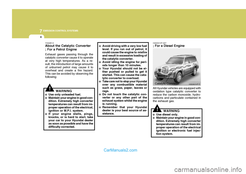
; For a Diesel Engine
!WARNING
o Use only unleaded fuel.
o Maintain your engine in good con- dition. Extremely high converter temperatures can result from im-proper operation of the electrical, ignition or M.P.I. system.
o If your engine stalls, pings, knocks, or is hard to start, takeyour car to your Hyundai dealer as soon as possible and have thedifficulty corrected. o Avoid driving with a very low fuel
level. If you run out of petrol, it could cause the engine to misfire and result in excessive loading ofthe catalytic converter.
o Avoid idling the engine for peri- ods longer than 10 minutes.
o Your Hyundai should not be ei- ther pushed or pulled to get itstarted. This can cause the cata- lytic converter to overload.
o Take care not to stop your Hyundai over any combustible material such as grass, paper, leaves orrags.
o Do not touch the catalytic con- verter or any other part of the exhaust system whilst the engine is running.
o Remember that your Hyundai dealer is your best source of as-sistance.
Catalytic Converter H020A01HP-D
!
All Hyundai vehicles are equipped with oxidation type catalytic converter toreduce the carbon monoxide, hydro- carbons and particulate contained in the exhaust gas.
WARNING
o Use diesel only.
o Maintain your engine in good con- dition. Extremely high converter temperatures can result from im- proper operation of the electricalignition or electronic fuel injec- tion system.
Page 531 of 539
9
VEHICLE SPECIFICATIONS
3
Petrol
3.5 V6
6-Cyl., V-type DOHC
3.67 x 3.38 in. (93.0 x 85.8 mm)
3497
10
1 - 2 - 3 - 4 - 5 - 6 Auto lash Auto lash
CHAMPION: RC10PYPB4 NGK: PFR5N-11
0.039 ~ 0.043 in. (1.0 ~ 1.1 mm)
800
BTDC 5° ± 2°
ITEMS
Engine Type Bore x Stroke Displacement (cc)Compression Ratio Firing Order
Valve Clearance Cold(Intake/Exhaust) (mm) Hot Spark Plug Spark Plug Gap Idle Speed (rpm) Ignition TimingENGINE
J070A03HP-EAT
Diesel
2.9 CRDi
4-Cyl., In-line DOHC
3.82 x 3.86 in. (97.1 x 98 mm)
2902
16.5
1 - 3 - 4 - 2 � �
- -
800 ± 100
Automatically Adjusted
Page 536 of 539

10
INDEX
3
Coolant temperature gauge .....................................1-57
If the engine overheats ............................................. 3-4
Number ..................................................................... 8-2
Oil ............................................................................. 6-4 Starting ..................................................................... 2-5
Engine Exhaust Can Be Dangerous! ........................... 2-2
F Fan Speed Control ................. .........................1-90, 1-101
Fog Light Switch Front ....................................................................... 1-62
Rear ........................................................................ 1-62
Four-Wheel Drive(4WD) ............................................. 2-14
Front Door Edge Warning Light ................................. 1-84
Front Seats
Adjustable head restraints ...................................... 1-17
Adjusting seatback angle ....................................... 1-17
Driver's seat lumbar support control .......................1-18
Seat adjust ment ..................................................... 1-16
Seat cushion height adjustment ............................. 1-19
Seat fore/aft adjustment ......................................... 1-16
Fuel Capacity ................................................................... 9-2
Gauge ..................................................................... 1-57
Recommendations .................................................... 1-2
Fuel-Filler Flap Remote release ........................................................ 1-2
Full-time 4WD Operation ............................................ 2-17
Fusible Links ............................................................. 6-25G
Glove Box ................................................................. 1-73
H Hatchback Door ......................................................... 1-78
Hazard Warning System ............................................ 1-65
Headlight Aiming Adjustment..................................... 6-33
Headlight Bulbs Replacement ....................................6-31
Headlight Leveling Device S ystem ............................1-85
Heated Front/Rear Window .. ......................................1-65
Heating and Cooling Control ......................................1-89
Heating and Ventilation
Air flow control ............................................. 1-91, 1-102
Air intake control ......................................... 1-91, 1-101
Defrosting/Defogging ............................................... 1-95
Fan speed control ........................................ 1-90, 1-101
Temperature control ................................................ 1-83
High-Mounted Rear Stop Light ...................................1-82
Horn ........................................................................... 1-84
I Ignition Switch ............................................................. 2-3
Illuminated ignition switch ......................................... 1-8
Immobiliser System ..................................................... 1-5
Indicator and Warning Lights ..................................... 1-50
Instrument Cluster and Indicator Lights ..................... 1-46
Interior Light ............................................................... 1-72
Interior Rearview Mirror .............................................. 1-77
Intermittent Wi pe Facility ........................................... 1-64