2005 Hyundai Terracan heating
[x] Cancel search: heatingPage 11 of 539

1. Multi-Function Light Switch/ Front Fog Light Switch
2. Instrument Cluster
3. Horn and Driver's Airbag (If Installed)
4. Rear Fog Light Switch (If Installed)
5. Windshield Wiper/Washer Switch
6. Panel Brightness Control Knob (Rheostat Switch)(If Installed)
7. Hazard Warning Switch
8. Cruise Control Main Switch (If Installed)
9. Headlight Leveling Switch (If Installed)
10. Audio System (If Installed)
11. Heating/Air Conditioning Control Panel
12. Glove Box
13. Passenger's Airbag (If Installed)
14. Hood Release Lever
CAUTION:
When installing a container of liquid air freshener inside the vehicle, do not place it near theinstrument cluster nor on the instrument panel surface. If there is any leakage from the air freshener onto these areas (Instrument cluster, instrument panel or air ventilator), it maydamage these parts. If the liquid from air freshener does leak onto these areas, wash them with water immediately.
! 15. Multi Box
16. Steering Wheel Tilt Lever (If Installed)
17. Remote Fuel-Filler Lid Release Lever
18. Cruise Control Switch (If Installed)
19. Cigarette Lighter/ Front Ashtray
20. Coin Holder
21. Shift Lever
22. Seat Warmer Switch (If Installed)
23. Front Power Outlet
24. Transfer Shift Knob
25. Parking Brake
26. Front Drink Holder
27. Rear Power Outlet
28. Rear Drink Holder
29. Rear Ashtray
Page 13 of 539

CAUTION:
When installing a container of liquid air freshener inside the vehicle, do not place it near the instrument cluster nor on the instrument panel surface. If there is any leakage from the air freshener onto these areas (Instrument cluster, instrument panel or air ventilator), it may damage these parts. If the liquid from air freshener does leak onto these areas, wash themwith water immediately.!
1. Passenger's Airbag (If Installed)
2. Glove Box
3. Heating/Air Conditioning Control Panel
4. Audio System (If Installed)
5. Headlight Leveling Switch (If Installed)
6. Cruise Control Main Switch (If Installed)
7. Hazard Warning Switch
8. Panel Brightness Control Knob (Rheostat Switch)
(If Installed)
9. Windshield Wiper/Washer Switch
10. Rear Fog Light Switch (If Installed)
11. Horn and Driver's Airbag (If Installed)
12. Instrument Cluster
13. Multi-Function Light Switch/ Front Fog Light Switch
14. Rear Ashtray 15. Rear Drink Holder
16. Rear Power Outlet
17. Front Drink Holder
18. Parking Brake
19. Transfer Shift Knob
20. Front Power Outlet
21. Seat Warmer Switch (If Installed)
22. Shift Lever
23. Coin Holder
24. Cigarette Lighter/ Front Ashtray
25. Steering Wheel Tilt Lever (If Installed)
26. Cruise Control Switch (If Installed)
27. Remote Fuel-Filler Lid Release Lever
28. Multi Box
29. Hood Release Lever
Page 15 of 539
Fuel Recommendations ............................................... 1-2
Breaking In Your New Hyundai .................................... 1-3
Keys .............................................................................. 1-4
Immobilizer System ...................................................... 1-5
Door Locks .................................................................1-11
Theft-Alarm System .................................................... 1-13
Power Windows .......................................................... 1-17
Seats .......................................................................... 1-18
Seat Belts ................................................................... 1-31
Child Restraint System............................................... 1-39
Supplemental Restraint (AIRBAG) System ............... 1-48
Instrument Cluster and Indicator Lights ..................... 1-54
Warning and Indicator Lights ..................................... 1-58
Multim eter ................................................................... 1-69
Multi-function Light Switch ......................................... 1-73
Windshield Wiper/Washer Switch .............................. 1-76
Sunroof ....................................................................... 1-84
Mirror .......................................................................... 1-88
Hood Release ............................................................. 1-96
Cruise Control .......................................................... 1-100
Heating and Cooling Control .................................... 1-103
Stereo Sound System .............................................. 1-119
Audio System ........................................................... 1-121Antenna .................................................................... 1-140FEATURES OF YOUR HYUNDAI
1
1
Page 78 of 539
1FEATURES OF YOUR HYUNDAI
64
should slow the vehicle and bring it to a complete stop in a safe location offthe roadway. After starting the engine, do not drive the vehicle until the vacuum level isabove 275 mmHg below atmosphere and warning light has turned off. If further trouble is experienced, the ve-hicle should not be driven at all but taken to a dealer by a professional towing service. B265C02HP-GAT
Diesel Preheat Indicator Light
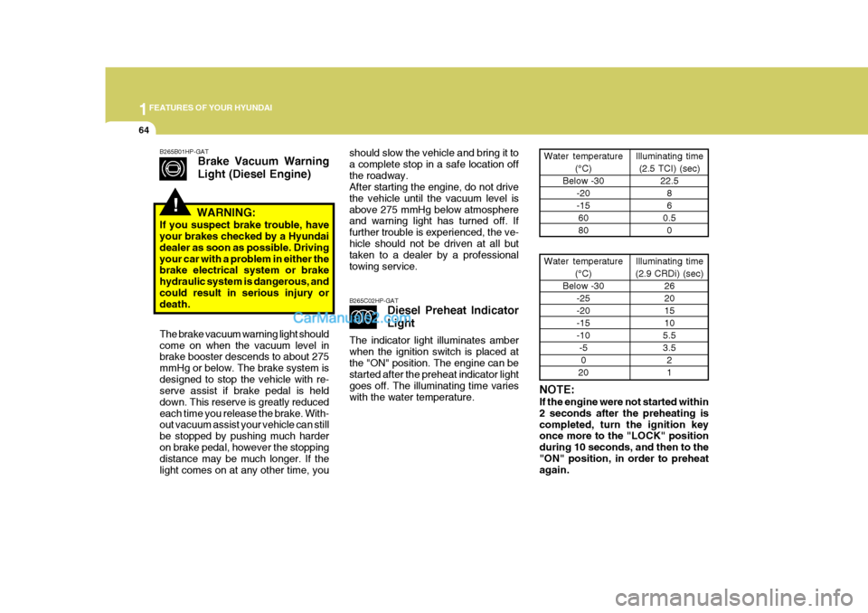
The indicator light illuminates amber when the ignition switch is placed atthe "ON" position. The engine can be started after the preheat indicator light goes off. The illuminating time varieswith the water temperature. NOTE: If the engine were not started within 2 seconds after the preheating iscompleted, turn the ignition key once more to the "LOCK" position during 10 seconds, and then to the"ON" position, in order to preheat again.Water temperature
(°C)
Below -30 -20 -156080 Illuminating time
(2.5 TCI) (sec) 22.586
0.5 0
Water temperature (°C)
Below -30 -25 -20-15-10-50
20 Illuminating time
(2.9 CRDi) (sec) 26201510
5.53.5 21
!
B265B01HP-GAT Brake Vacuum Warning Light (Diesel Engine)
WARNING:
If you suspect brake trouble, have your brakes checked by a Hyundai dealer as soon as possible. Drivingyour car with a problem in either the brake electrical system or brake hydraulic system is dangerous, andcould result in serious injury or death. The brake vacuum warning light should come on when the vacuum level in brake booster descends to about 275 mmHg or below. The brake system isdesigned to stop the vehicle with re- serve assist if brake pedal is held down. This reserve is greatly reducedeach time you release the brake. With- out vacuum assist your vehicle can still be stopped by pushing much harderon brake pedal, however the stopping distance may be much longer. If the light comes on at any other time, you
Page 94 of 539
1FEATURES OF YOUR HYUNDAI
80CIGARETTE LIGHTERPOWER OUTLET
!
CAUTION:
Do not use electric accessories or equipment other than the Hyundai genuine parts in the socket. B500D08HP-AAT (If Installed)
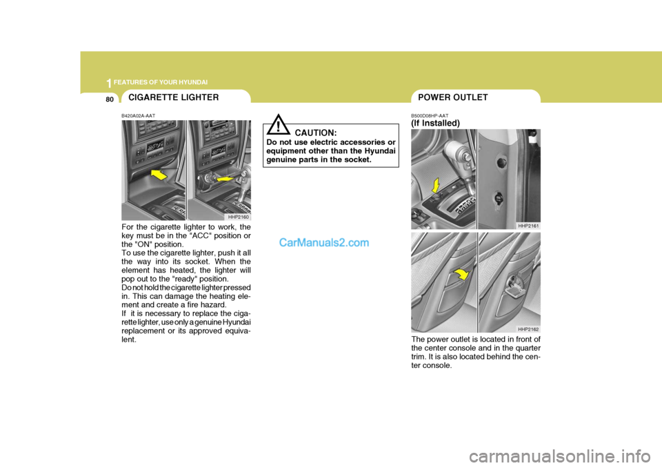
B420A02A-AAT For the cigarette lighter to work, the key must be in the "ACC" position or the "ON" position. To use the cigarette lighter, push it all the way into its socket. When theelement has heated, the lighter will pop out to the "ready" position. Do not hold the cigarette lighter pressedin. This can damage the heating ele- ment and create a fire hazard. If it is necessary to replace the ciga-rette lighter, use only a genuine Hyundai replacement or its approved equiva- lent. HHP2160
HHP2162HHP2161
The power outlet is located in front of the center console and in the quarter trim. It is also located behind the cen- ter console.
Page 117 of 539
1
FEATURES OF YOUR HYUNDAI
103
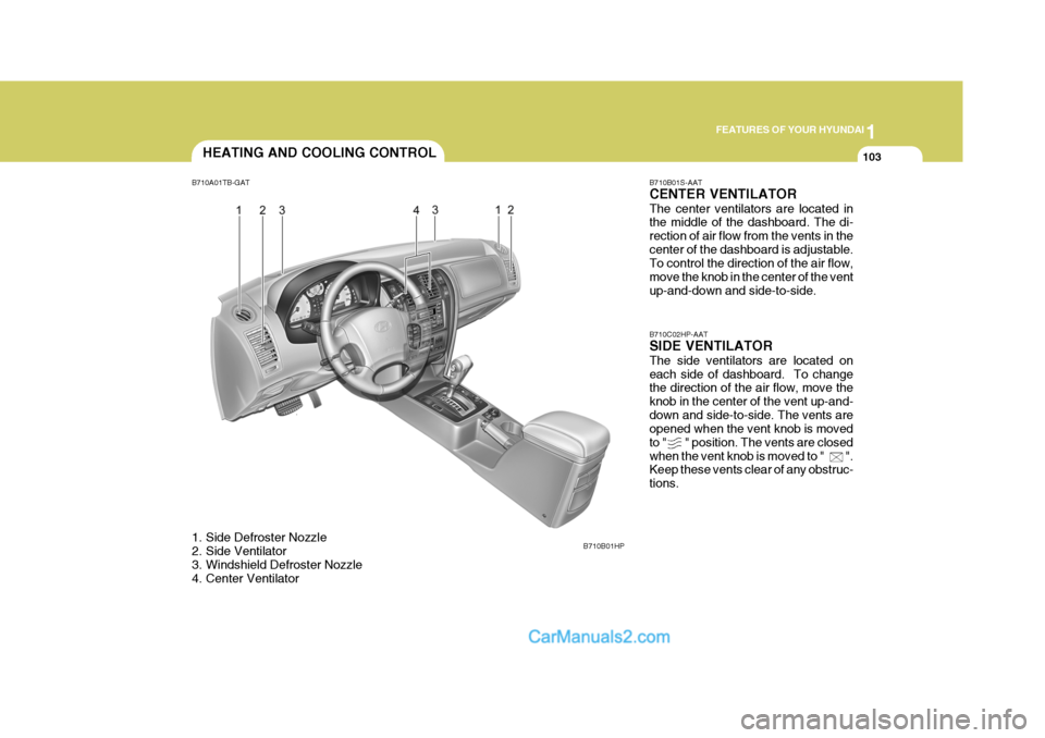
B710B01S-AAT CENTER VENTILATOR The center ventilators are located in the middle of the dashboard. The di- rection of air flow from the vents in thecenter of the dashboard is adjustable. To control the direction of the air flow, move the knob in the center of the ventup-and-down and side-to-side. B710C02HP-AAT SIDE VENTILATOR The side ventilators are located on each side of dashboard. To change the direction of the air flow, move the knob in the center of the vent up-and-down and side-to-side. The vents are opened when the vent knob is moved to " " position. The vents are closedwhen the vent knob is moved to " ". Keep these vents clear of any obstruc- tions.
HEATING AND COOLING CONTROL
B710A01TB-GAT
1. Side Defroster Nozzle
2. Side Ventilator
3. Windshield Defroster Nozzle
4. Center Ventilator B710B01HP
Page 118 of 539
1FEATURES OF YOUR HYUNDAI
104HEATING AND VENTILATION
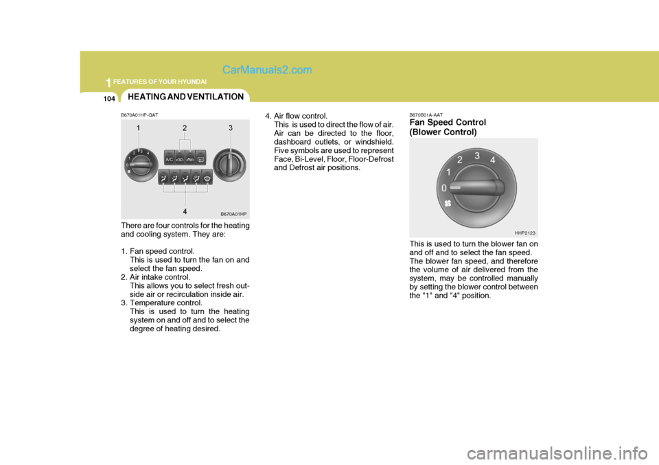
B670A01HP-GAT There are four controls for the heating and cooling system. They are:
1. Fan speed control. This is used to turn the fan on and select the fan speed.
2. Air intake control.
This allows you to select fresh out-side air or recirculation inside air.
3. Temperature control.
This is used to turn the heatingsystem on and off and to select the degree of heating desired. 4. Air flow control.
This is used to direct the flow of air. Air can be directed to the floor, dashboard outlets, or windshield. Five symbols are used to representFace, Bi-Level, Floor, Floor-Defrost and Defrost air positions.
B670A01HP B670B01A-AAT Fan Speed Control (Blower Control) This is used to turn the blower fan on and off and to select the fan speed.The blower fan speed, and therefore the volume of air delivered from the system, may be controlled manuallyby setting the blower control between the "1" and "4" position.
HHP2123
Page 119 of 539
1
FEATURES OF YOUR HYUNDAI
105
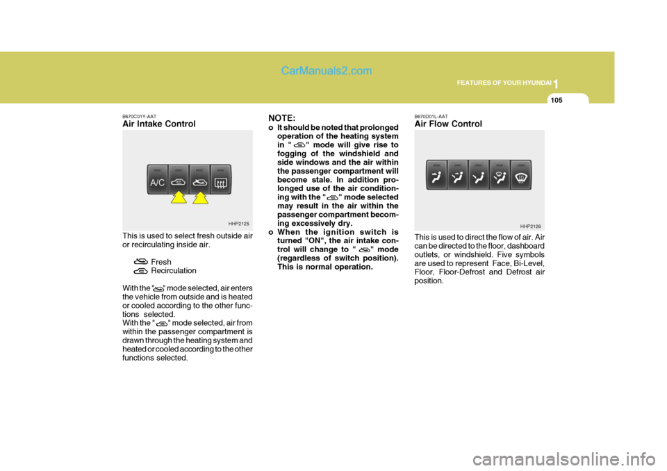
B670C01Y-AAT Air Intake Control This is used to select fresh outside air or recirculating inside air.
FreshRecirculation
With the " " mode selected, air entersthe vehicle from outside and is heated or cooled according to the other func-tions selected. With the " " mode selected, air from within the passenger compartment isdrawn through the heating system and heated or cooled according to the other functions selected. NOTE:
o It should be noted that prolonged
operation of the heating system in " " mode will give rise tofogging of the windshield and side windows and the air within the passenger compartment willbecome stale. In addition pro- longed use of the air condition- ing with the " " mode selectedmay result in the air within the passenger compartment becom- ing excessively dry.
o When the ignition switch is turned "ON", the air intake con-trol will change to " " mode(regardless of switch position). This is normal operation. B670D01L-AAT Air Flow Control This is used to direct the flow of air. Air can be directed to the floor, dashboard outlets, or windshield. Five symbolsare used to represent Face, Bi-Level, Floor, Floor-Defrost and Defrost air position.
HHP2125
HHP2126