2005 Hyundai Matrix ECU
[x] Cancel search: ECUPage 61 of 407

1- 53
CONTROLS AND EQUIPMENT
70 kg (154 lb)
EVENLY DISTRBUTED
HFC2106
B630A01FC-EAT
ROOF RACK (Not all models) If your Hyundai has a roof rack, you can load
things on top of your vehicle. Crossrails and fixing components to adapt the roof rack onyour vehicle may be obtained from an Hyundaiauthorised repairer.
CAUTION:
o The following specifications are recom- mended when loading cargo or luggage.
ROOF RACK
o Loading cargo or luggage above 70 kg (154 lb) on the roof rack may damage your vehicle. When you carry large objects, never let them hang over the rear or the sides ofyour vehicle.
o To prevent damage or loss of cargo as you are driving, check frequently tomake sure the luggage carrier and cargoare still securely fastened.
o Always drive your vehicle at a moderate speed.
o To use the roof rails as a roof rack, you must fit the roof rails with two or morecrossrails or equivalent before carryingcargo or lugguage on the roof.
o When crossrail is adapted, you can load items on the roof rack.
o Loading cargo or luggage over speci- fication on the roof rack may damagestability of your vehicle.
B650A01FC-DAT CARGO AREA COVER
B640A01FC
Nothing should be carried on top of the lug-
gage cover. Loose materials could result in injury to vehicle occupants during sudden brak- ing. B560B01O-GAT
Auto Fuel Cut Switch (Gasoline Engine)HFC4001
The auto fuel cut switch is located on the
driver's side of the engine compartment.
In the event of a collision or sudden impact,
the auto fuel cut device cuts off the fuel supply. If this device is activated, it must bereset by pressing in on the top of the switchbefore the engine can be restarted.
WARNING: Before resetting the auto fuel cut switch,
the fuel line should be checked for fuel leaks.
Page 62 of 407

CONTROLS AND EQUIPMENT
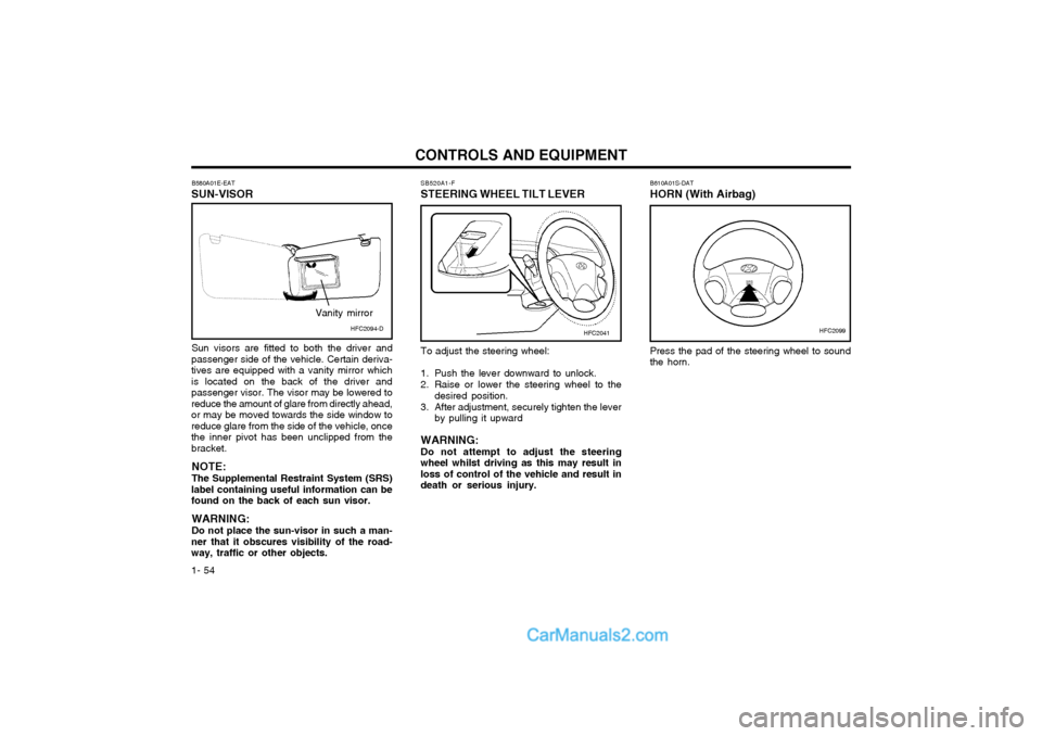
1- 54 B610A01S-DAT HORN (With Airbag) Press the pad of the steering wheel to sound the horn.
B580A01E-EAT
SUN-VISOR
Sun visors are fitted to both the driver and
passenger side of the vehicle. Certain deriva-tives are equipped with a vanity mirror whichis located on the back of the driver andpassenger visor. The visor may be lowered toreduce the amount of glare from directly ahead,or may be moved towards the side window toreduce glare from the side of the vehicle, oncethe inner pivot has been unclipped from thebracket.
NOTE: The Supplemental Restraint System (SRS)
label containing useful information can be found on the back of each sun visor.
WARNING: Do not place the sun-visor in such a man-
ner that it obscures visibility of the road- way, traffic or other objects. SB520A1-F
STEERING WHEEL TILT LEVER
HFC2099HFC2041HFC2094-D
Vanity mirror
To adjust the steering wheel:
1. Push the lever downward to unlock.
2. Raise or lower the steering wheel to the
desired position.
3. After adjustment, securely tighten the lever by pulling it upward
WARNING: Do not attempt to adjust the steeringwheel whilst driving as this may result inloss of control of the vehicle and result indeath or serious injury.
Page 87 of 407

DRIVING YOUR HYUNDAI 2- 15
YC200E2-E
Trailer or Vehicle Towing Tips
1. Before towing, check towbar ball and safe- ty cable connections as well as proper operation of the trailer running lights, brake lights, and turn signals.
2. Always drive your vehicle at a moderate speed (Less than 60 MPH)
3. Trailer towing requires more fuel than nor- mal conditions.
4. To maintain engine braking efficiency and electrical charging performance, do not usefifth gear (manual transaxle) or overdrive (automatic transaxle). 5. Always secure items in the trailer to pre-
vent load shift whilst driving.
6. Check the condition and air pressure of all tyres on the trailer and your car. Low tyrepressure can seriously affect the handling. Also check the spare tyre.
7. The vehicle/trailer combination is more af- fected by crosswind and buffeting. When being passed by a large vehicle,keep a constant speed and steer straight ahead. If there is too much wind buffeting slow down to get out of the other vehicle's air turbulence.
8. When parking your car and trailer, espe- cially on a hill, be sure to follow all thenormal precautions. Turn your front wheels into the curb, set the parking brake firmly, and put the transaxle in 1st or Reverse (manual) or Park (automatic). In addition, place wheel chocks at each of the trailer's tyres.
9. If the trailer has electric brakes, start your vehicle and trailer moving, and then applythe trailer brake controller by hand to be sure the brakes are working. This lets you check your electrical connection at the same time.
10.During your trip, check occasionally to be sure that the load is secure, and that thelights and any trailer brakes are still work- ing. 11.Avoid jerky starts, sudden acceleration or
sudden stops.
12.Avoid sharp turns and rapid lane changes.
13.Avoid holding the brake pedal down too long or too frequently. This could causethe brakes to overheat, resulting in re- duced braking efficiency.
14.When going down a hill, shift into a lower gear and use the engine braking effect. When ascending a long grade, downshiftthe transaxle to a lower gear and reduce speed to reduce chances of engine over- loading and/or overheating.
15.If you have to stop whilst going uphill, do not hold the vehicle in place by pressing onthe accelerator. This can cause the auto- matic transaxle to overheat. Use the park- ing brake or footbrake.
NOTE:When towing check transaxle fluid more
frequently.
CAUTION:If overheating should occur when towing,
(temperature gauge reads near red zone), taking the following action may reduce or eliminate the problem.
1. Turn off the air conditioner.
2. Reduce highway speed.
3. Select a lower gear when going uphill.
4. While in stop and go traffic, place the gear selection in park or neutral andidle the engine at a higher speed.
Towing BracketAttachment Location
o The maximum permissible static verti-
cal load on the coupling device : 52kg
o The maximum permissible overhang of the coupling point : 760 mm.
C190E01FC
Page 90 of 407

3-3
IN CASE OF EMERGENCY
If the drive belt seems to be satisfactory, check for coolant leaking from the radiator, hoses or under the car. (If the air condi- tioning had been in use, it is normal for cold water to be draining from it).
WARNING: Whilst the engine is running, keep hands and clothing away from moving parts such as the fan and drive belts to prevent injury. WARNING (Diesel only): Never work on injection system with en-gine running or within 30 seconds after shutting off engine. High pressure pump, rail, injectors and high pressure pipes are subject to high pressure even after the engine stopped. The fuel jet produced by fuel leaks may cause serious injury, if it touch the body. People using pacemak- ers should ensure that they keep a dis- tance of 30cm from the ECU or wiring harness within the engine room whilst engine is running, since the high currents in the Common Rail system produce con- siderable magnetic fields.
5. If the water pump drive belt is broken or coolant is leaking out, stop the engine immediately and call the nearest Hyundai authorised repairer for assistance. WARNING:Do not remove the radiator cap when theengine is hot since steam and boiling water may be ejected from the radiator resulting in burns or scalding.
6. If the cause of the overheating cannot be found, wait until the engine temperature has returned to normal. Then, if coolant has been lost, carefully remove the radia- tor cap and add water to bring the fluid level in the reservoir up to the base of the radiator fill opening. Fill the coolant expan- sion tank to the halfway mark.
7. Proceed with caution until it is established that the engine is operating normally. If theengine overheats repeatedly, the advice of a Hyundai authorised repairer should be sought.
CAUTION:Serious loss of coolant indicates there is a leak in the cooling system and this should be checked as soon as possible by a Hyundai authorised repairer. D040A01FC-EAT
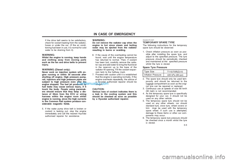
TEMPORARY SPARE TYRE The following instructions for the temporary
spare tyre should be observed:
1. Check inflation pressure as soon as pos-
sible after installing the spare tyre, and adjust to the specified pressure. The tyre pressure should be periodically checked and maintained at the specified pressure whilst the tyre is stored.
2. The spare tyre should only be used tem- porarily and should be returned to the luggage compartment as soon as the origi- nal tyre can be repaired or replaced.
3. Continuous use at speeds of over 80 km/h
(50 mph) is not recommended.
4. As the temporary spare tyre is specifically designed for your car, it should not beused on any other vehicle.
5. The temporary spare tyre should not be used on any other wheels, nor shouldstandard tyre, snow tyre, wheel covers or trim rings be used with the temporary spare wheel. If such use is attempted, damage to these items or other car com- ponents may occur.
6. The temporary spare tyre pressure should be checked once a month whilst the tyreis stored.
Spare Tyre Pressure
Type Size Inflation Pressure T115/70R(D)15420 kPa (60 psi)
Page 94 of 407

3-7
IN CASE OF EMERGENCY
WARNING: It is important that the faces of the wheeland hub are clean prior to installing the wheel. The prescence of dirt or other mat- ter in the wheel or hub faces could result in the wheel nuts becoming loose whilst the vehicle is being driven. SD070I1-E
7. Re-install Wheel Nuts
Fit the wheel nuts onto the studs and tighten with the wheel brace.
SD070H1-E 6. Changing Wheels Using the wheel brace, remove the nuts and slide the wheel off the hub and wheel studs. Lie the wheel flat to prevent it from rolling. Ensure that the faces of the wheel and hub are clean. Position the spare wheel over the studs and slide it up to the hub.
STA3071H
D060H01FC-D
D060G01FC
SD070J1-E
8. Lower Vehicle and Tighten Nuts
Lower the car to the ground turning the wheel
nut wrench counterclockwise. When the ve- hicle is firmly on the ground, remove the jack and tighten the wheel nuts securely. At the first available opportunity, the wheel nut torque should be checked with a suitable torque wrench.
Wheel nut tightening torqueSteel wheel & aluminium alloy wheel: 90-110 Nm (65-80 lb.ft)
D060I01FC-D
Page 105 of 407

VEHICLE MAINTENANCE REQUIREMENTS
5- 6 6ZF060D2-A
o Fuel lines, Fuel Hoses and
Connections
Check the fuel lines, fuel hoses and connec- tions for leakage and damage. Replace anydamaged or leaking parts immediately.
WARNING (Diesel only): Never work on injection system with en-gine running or within 30 seconds aftershutting off engine. High pressure pump,rail, injectors and high pressure pipes aresubject to high pressure even after theengine stopped. The fuel jet produced byfuel leaks may cause serious injury, if itcontacts the body. People using pace-makers should ensure that they keep adistance of 30cm from the ECU or wiringharness within the engine room whilstengine is running, since the high currentsin the Common Rail system produce con-siderable magnetic fields. 6ZF060E1-A
o Timing Belt Replace timimg belt and inspect all associated parts related for damage and deformation.Replace any damaged parts immediately. 6ZF060G1-A
o Vapour Hose and Fuel Filler Cap The vapour hose and fuel filler cap should be inspected at those intervals specified in themaintenance schedule. Make sure that a newvapour hose or fuel filler cap is correctlyreplaced. 6ZF060F1-A
o Vacuum, Crankcase
Ventilation Hoses
Inspect the surface of hoses for evidence of heat and/or mechanical damage. Hard andbrittle rubber, cracking, tears, cuts, abra-sions, and excessive swelling indicate dete-rioration. Particular attention should be paid toexamining those hose surfaces nearest tohigh heat sources, such as the exhaustmanifold.Inspect the hose routing to assure that thehoses do not come in contact with any heatsource, sharp edges or moving componentwhich might cause heat damage or mechani-cal wear. Inspect all hose connections, suchas clamps and couplings, to make sure theyare secure, and that no leaks are present.Hoses should be replaced immediately if thereis any evidence of deterioration or damage.
6ZF060A1-A
EXPLANATION OF SCHEDULED MAINTENANCE ITEMS
6ZF060M1-A
o Engine Oil and Filter The engine oil and filter should be changed at
the intervals specified in the maintenance schedule. If the car is being driven in severeconditions, more frequent oil and filter changesare required.
6ZF060B1-A
o Drive Belts Inspect all drive belts for evidence of cuts,
cracks, excessive wear or oil contaminationand replace if necessary. Drive belts shouldbe checked periodically for proper tensionand adjusted as necessary.
6ZF060C1-A
o Fuel Filter A clogged filter can limit the speed at which the
vehicle may be driven, damage the emissionsystem and cause hard starting. If an exces-sive amount of foreign matter accumulates inthe fuel tank, the filter may require replace-ment more frequently.
After installing a new filter, run the engine for
several minutes, and check for leaks at theconnections.
Page 123 of 407

OWNER MAINTENANCE
6-16 SG120D1-E Brake Fluid Level The fluid level in the brake fluid reservoir should be checked periodically. The levelshould be between the "MIN" and "MAX"marks on the side of the reservoir. If the levelis at or below the "MIN" mark, fluid should beadded having carefully cleaned the area sur-rounding the reservoir cap to ensure that dirtis not allowed to enter the system. It shouldbe noted that the brake fluid level will de-crease slightly as the friction linings of thepads and shoes become worn and that this isa normal condition.
SG120A1-E
BRAKE SYSTEM CHECKING CAUTION:
Correct operation of the braking system is
essential to the safe operation of the vehicle and therefore, any maintenance operationsother than those listed below should beentrusted to a Hyundai authorised re-pairer.
SG120C2-E
Brake Fluid Recommendations
Only brake fluid conforming to DOT 3 or
DOT 4 specifications or higher may be usedin the braking system. Care should be takento observe the instructions and precautionsprinted upon the container.
HFC5005
Petrol engine
People using pacemakers should ensure that they keep a distance of 30cm fromthe ECU or wiring harness within theengine room whilst engine is running,since the high currents in the CommonRail system produce considerable mag-netic fields. Fluid Capacity The total fluid capacity of the transmission unit is 6.1 litres (1.6 DOHC)/6.7 litres(1.8 DOHC).
Fluid level should be within this range
C090A03FC
�Î�Î
WARNING: The cooling fan is controlled by engine
coolant temperature and may sometimes operate even when the engine is not run-ning. Use extreme caution when workingnear the blades of the cooling fan so thatyou are not injured by a rotating fan blade.As the engine coolant temperature de-creases, the fan will automatically shutoff. This is a normal condition.
WARNING (Diesel only): Never work on injection system with en-
gine running or within 30 seconds after shutting off engine. High pressure pump,rail, injectors and high pressure pipes aresubject to high pressure even after theengine stopped. The fuel jet produced byfuel leaks may cause serious injury, if itcontacts the body.
Page 135 of 407

OWNER MAINTENANCE
6-28
G200C01FC-EAT
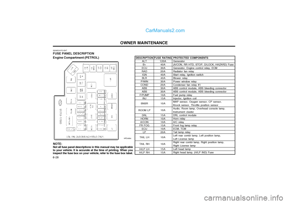
FUSE PANEL DESCRIPTION Engine Compartment (PETROL)
HFC4004PROTECTED COMPONENTS Generator (A/CON, RR HTD, STOP, D/LOCK, HAZARD) Fuse Generator, Engine control relay, ECM Radiator fan relay Start relay, Ignition switch Blower relay Power window relay Condenser fan relay #1 ABS control module, ABS bleeding connector ABS control module, ABS bleeding connector Fuel pump relay Injector, lgnition coil MAP sensor, Oxygen sensor, CP sensor, Knock sensor, Throttle position sensor Audio, Room lamp, Overhead console lamp, lnstrument cluster DRL control module Horn relay A/C relay Front fog lamp relay ECM, TCM Tail lamp relay Left rear combi lamp, Left position lamp, Left License lamp Right rear combi lamp, Right position lamp, Right License lamp Left head lamp Right head lamp, (H/LP IND) Fuse
FUSE RATING
120A40A 30A 20A 40A 40A 30A 20A 30A 30A 10A 15A 10A 10A 15A 10A 10A 15A 10A 20A 10A 10A 15A 15A
DESCRIPTION
ALTB+
ECU RAD IGN
BLR
P/WIN
COND
ABSABS
F/PUMP INJ
SNSR
ROOM LP DRL
HORN
A/CON
FR FOG
ECULP
TAIL LH
TAIL RH H/LP LH
H/LP RH
NOTE: Not all fuse panel descriptions in this manual may be applicable
to your vehicle. It is accurate at the time of printing. When you inspect the fuse box on your vehicle, refer to the fuse box label.