Page 11 of 205

1. Multi-function light switch
2. Seat warmer switch (If installed)
3. Horn/Driver's side airbag (If installed)
4. Rear heater switch (If installed)
5. Windshield wiper/Washer switch
6. Hazard warning switch
7. Front fog light switch (If installed)
8. 4WD Switch (If installed)
9. Rear fog light switch (If installed)
10. Front/Rear window defroster switch
11. Passenger's side airbag (If installed)
12. Glove box13. Headlight leveling device switch (If installed)
14. ECT switch (Automatic transmission only)
15. Fuel-filler lid release lever
16. Hood release lever
17. Panel brightness control knob (Rheostat) (If installed)
18. Engine RPM adjustment knob (If installed)
19. Heater/Air conditioner control panel
20. Cigarette lighter
21. Ashtray
22. Drink holder
23. Audio system (If installed)
24. Digital clock (If installed)
CAUTION:
When installing the container of liquid air refresher inside a vehicle, do not place it near theinstrument cluster nor on the crash pad surface. If there is any leakage from the air refresher onto these areas (Instrument cluster, crash pad or air ventilator), it may damage these parts. If the liquid from air refresher does leak onto these areas, wash them with water immediately.
!
Page 13 of 205
1. Multi-function light switch
2. Horn/Driver's side airbag (If installed)
3. Windshield wiper/Washer switch
4. Hazard warning switch
5. Front fog light switch (If installed)
6. Rear fog light switch (If installed)
7. Outside rearview mirror heater switch (If installed)
8. Glove box
9. Hood release lever10. Headlight leveling device switch (If installed)
11. Engine RPM Adjustment Knob
12. Heater/Air conditioner control panel
13. Cigarette lighter
14. Ashtray
15. Drink holder
16. Audio system (If installed)
17. Digital clock (If installed)
CAUTION:
When installing the container of liquid air refresher inside a vehicle, do not place it near theinstrument cluster nor on the crash pad surface. If there is any leakage from the air refresheronto these areas (Instrument cluster, crash pad or air ventilator), it may damage these parts. If the liquid from air refresher does leak onto these areas, wash them with water immediately.
!
Page 97 of 205

3
STARTING AND OPERATING
29
D180C01P-GAT Battery The capacity of the battery is reduced at low temperatutes.This is an inevitable result of its chemi- cal and physical properties. This is why a very cold battery, particularlyone that is not fully charged anyway, will only deliver a fraction of the starter current which is normally available.It is recommended that you have the battery checked by an authorized HYUNDAI dealer before the start ofcold weather and, if necessary, have it charged. This not only ensures reliable starting,but a battery which is kept fully charged also has a longer life. C160G02A-AAT To Keep Locks from Freezing To keep the locks from freezing, squirt an approved de-icer fluid or glycerineinto the key opening. If a lock is cov- ered with ice, squirt it with an approved de-icing fluid to remove the ice. If thelock is frozen internally, you may be able to thaw it out by using a heated key. Handle the heated key with careto avoid burning your fingers. NOTE: The proper temperature for using the immobilizer key is from -40°C to 80°C. If you heat the immobilizer key over 80°C to open the frozenlock, it may cause damage to the transponder in its head.
D180G01P-GAT Door locks To prevent the door locks from freez- ing up, the lock cylinders should be masked with tape, etc., when washingthe vehicle in cold weather to prevent the entrance of water.
D180D01P-GAT Washer fluid To ensure proper operation of the wind- shield or rear window at low tempera-tures, anti-freeze should be added to the washer fluid at a rate of one part antifreeze to one part water. D180E01P-GAT Wiper blades Before operating the wipers, check the wiper blades to confirm that they arenot frozen to the windshield or tailgate. If the blades are frozen to the wind- shield or tailgate, do not operate thewipers until the ice has melted and the blades are freed. D180F01P-GAT Ventilation slots The ventilation slots in the headlight housing on the assistant seat side should be brushed clear after a heavysnowfall so that the operation of the heating and ventilation systems will not be impaired.
Page 102 of 205

4
Tools and Jack ............................................................. 4-2
Spare Tire ..................................................................... 4-3
If You Have a Flat Tire ................................................. 4-6
Changing a Flat Tire ..................................................... 4-7Towing........................................................................ 4-13
Bleeding the Fuel System .......................................... 4-18
Removal of Water from the Fuel Filter ....................... 4-19
If the Engine Will Not Start ......................................... 4-20
Jump Starting ............................................................. 4-21
If the Engine Overheats ............................................. 4-22
Checking and Replacing Fuses ................................. 4-24
Headlight Aiming Adjustment ..................................... 4-26
Replacement of Light Bulbs ....................................... 4-27
Bulb Wattage .............................................................. 4-35
Fuse Panel Description .............................................. 4-37
IN CASE OF EMERGENCY
4
Page 130 of 205

4
CORROSION PREVENTION AND APPEARANCE CARE
29
4
IN CASE OF EMERGENCY
29
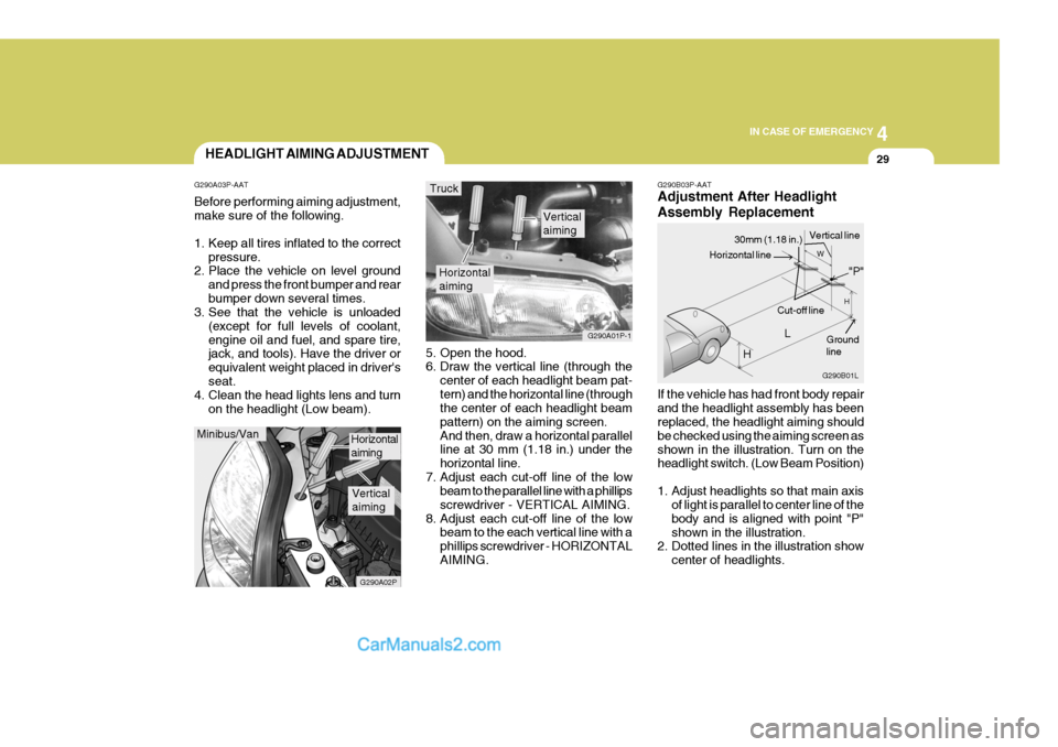
G290B03P-AAT Adjustment After Headlight Assembly Replacement If the vehicle has had front body repair and the headlight assembly has been replaced, the headlight aiming should be checked using the aiming screen asshown in the illustration. Turn on the headlight switch. (Low Beam Position)
1. Adjust headlights so that main axis
of light is parallel to center line of the body and is aligned with point "P"shown in the illustration.
2. Dotted lines in the illustration show
center of headlights.
5. Open the hood.
6. Draw the vertical line (through the
center of each headlight beam pat- tern) and the horizontal line (through the center of each headlight beam pattern) on the aiming screen.And then, draw a horizontal parallel line at 30 mm (1.18 in.) under the horizontal line.
7. Adjust each cut-off line of the low beam to the parallel line with a phillipsscrewdriver - VERTICAL AIMING.
8. Adjust each cut-off line of the low beam to the each vertical line with aphillips screwdriver - HORIZONTALAIMING.
Horizontal aiming
Verticalaiming
G290A01P-1
Truck
G290B01L
LW
H
H Cut-off line
Ground line
"P"
Horizontal line
30mm (1.18 in.) Vertical line
HEADLIGHT AIMING ADJUSTMENT
G290A03P-AAT Before performing aiming adjustment, make sure of the following.
1. Keep all tires inflated to the correct pressure.
2. Place the vehicle on level ground
and press the front bumper and rear bumper down several times.
3. See that the vehicle is unloaded
(except for full levels of coolant,engine oil and fuel, and spare tire, jack, and tools). Have the driver or equivalent weight placed in driver'sseat.
4. Clean the head lights lens and turn
on the headlight (Low beam).
Minibus/Van
G290A02P
Horizontal aiming
Verticalaiming
Page 131 of 205
44IN CASE OF EMERGENCY
30
Specifications: "H": Horizontal center line of headlights from ground "W":Distance between each headlight cen-ter "L": Distance between the headlights and the wall that the lights are tested against : 3,000 mm (118.11 in.).
2WD 4WD
Long wheel base
Extra long
wheel base
MINIBUS 894
(35.20) 1006
(39.61)
- - VAN
855
(33.66)
--- TRUCK
--
847
(33.35) 845
(33.27)2WD 4WD
Long wheel base
Extra long
wheel base
MINIBUS
- - VAN
-- TRUCK
--
1272
(50.08)
1380
(54.33)
REPLACEMENT OF LIGHT BULBS
G260A02A-AAT Before attempting to replace a head- light bulb, be sure the switch is turned to the "OFF" position. The next paragraph shows how toreach the headlight bulbs so they may be changed. Be sure to replace the burned-out bulb with one of the samenumber and wattage rating. See page 4-35 for the wattage descrip- tions.
CAUTION:
Keep the lamps out of contact withpetroleum products, such as oil,gasoline, etc.
!
mm(in.)
mm(in.)
Page 132 of 205
4
CORROSION PREVENTION AND APPEARANCE CARE
31
4
IN CASE OF EMERGENCY
31
HSRFL274
7. Push the bulb spring to remove the headlight bulb. HSRFL273
6. Turn the plastic cover counterclock- wise and remove it.
4. Using a spanner of the correct size,
remove the headlight assembly mounting bolts.
HSRFL272
5. Disconnect the power cord from the back of the headlight.
Replacement instructions:
1. Allow the bulb to cool. Wear eye
protection.
2. Open the engine hood.
3. Always grasp the bulb by its plastic base, avoid touching the glass. HSRFL270
G270A01P-GAT HEADLIGHT AND FRONT TURN SIGNAL LIGHT (Minibus/van)
Turn signal light
HSRFL271
Front position light
Headlight
Page 133 of 205

44IN CASE OF EMERGENCY
32
8. Remove the protective cap from the
replacement bulb and install the new bulb by matching the plastic base with the headlight hole. Retighten the bulb spring and reconnect thepower cord.
9. Use the protective cap and carton to
promptly dispose of the old bulb.
10.Check for proper headlight aim.
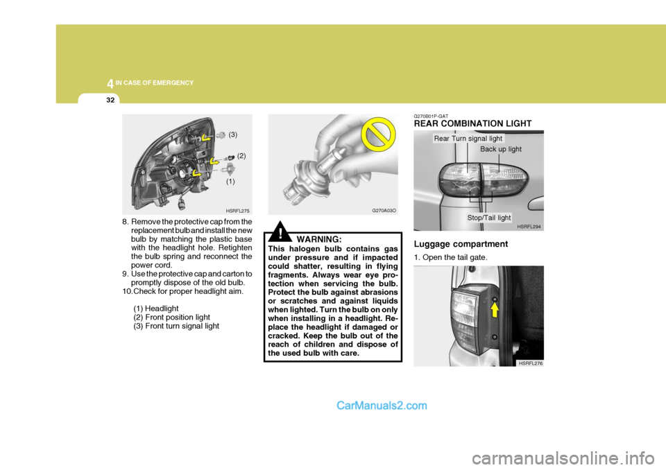
(1) Headlight(2) Front position light (3) Front turn signal light HSRFL275
(1)
(2)
(3)
!
G270A03O
WARNING:
This halogen bulb contains gas under pressure and if impacted could shatter, resulting in flying fragments. Always wear eye pro-tection when servicing the bulb. Protect the bulb against abrasions or scratches and against liquidswhen lighted. Turn the bulb on only when installing in a headlight. Re- place the headlight if damaged orcracked. Keep the bulb out of the reach of children and dispose of the used bulb with care.
HSRFL276
G270B01P-GAT REAR COMBINATION LIGHT Luggage compartment 1. Open the tail gate.
HSRFL294
Rear Turn signal light
Back up light
Stop/Tail light