Page 18 of 205

1BEFORE DRIVING YOUR VEHICLE
4
B070A01P-GAT MAINTENANCE It is necessary to maintain your vehicle in top operating condition in order to enjoy safe and pleasant driving.Some maintenance items can be done by the owner (Consumer information), while others should be done only by anauthorized dealer (periodic inspection and maintenance). For the maintenance items to be doneby the owner, prepare the appropriate materials and tools and follow the pro- cedures given in the "Consumer infor- mation" section of this manual. However, the periodic inspection andmaintenance should not be attempted by the owner, but should be done by an authorized HYUNDAI dealer.Correct performance of the periodic inspection and maintenance items re- quires specialized knowledge andequipment. Having these items performed by an authorized HYUNDAI dealer with thelatest technology and equipment will ensure that your vehicle is maintained for optimum performance, economy,and safety. In addition, having all periodic inspec-tion and maintenance done by an au-thorized HYUNDAI dealer is a prereq- uisite for validity of the warranty on your vehicle in the event of a claim.Refer to the separate "Service Book- let" for the periodic inspection and maintenance items and intervals. B080A01P-GAT INSTALLATION OF ACCESSO- RIES Consult an authorized HYUNDAI dealer when installing accessories.
o Installation of some accessories
may be restricted by regulations.
o Improper installation of electrical
parts could cause fire.
o Never use tires or wheels which do not meet specifications. For wheel and tire sizes, refer to the"CONSUMER INFORMATION" section of this manual.
VEHICLE IDENTIFICATION NUMBER (VIN)
B050A02P-GAT The vehicle identification plate is at- tached on the fender inner panel asshown in the illustration. The vehicle identification number (VIN) is the num- ber used in registering your car and inall legal matters pertaining to its own- ership, etc. HSRFL049
Page 102 of 205

4
Tools and Jack ............................................................. 4-2
Spare Tire ..................................................................... 4-3
If You Have a Flat Tire ................................................. 4-6
Changing a Flat Tire ..................................................... 4-7Towing........................................................................ 4-13
Bleeding the Fuel System .......................................... 4-18
Removal of Water from the Fuel Filter ....................... 4-19
If the Engine Will Not Start ......................................... 4-20
Jump Starting ............................................................. 4-21
If the Engine Overheats ............................................. 4-22
Checking and Replacing Fuses ................................. 4-24
Headlight Aiming Adjustment ..................................... 4-26
Replacement of Light Bulbs ....................................... 4-27
Bulb Wattage .............................................................. 4-35
Fuse Panel Description .............................................. 4-37
IN CASE OF EMERGENCY
4
Page 103 of 205
44IN CASE OF EMERGENCY
2
Release valve
TOOLS AND JACK
E010A01P-GAT To provide for cases of emergency, always remember where the tools and jack are stowed and how the jack is removed for use.
E010B03P-GAT Storage places E010C03P-GAT TOOLS
E020A01P-GATJACK To use the jack
The tool box is at the right rear corner of the luggage compartment (minibus/ van) or on the floor behind the seat(truck). Minibus/Van Truck
1. Tool case
2. Wheel nut wrench
3. Screwdriver
4. Spare wheel carrier wrench(Truck only) 4
Turn the knob clockwise, and then remove the lid. Remove the securing nut, and then take out the jack.
E010B01P-2 E010C03P
E020A01P
Minibus/Van Truck
Securing nut
Ram 1
2 3
Page 113 of 205

44IN CASE OF EMERGENCY
12
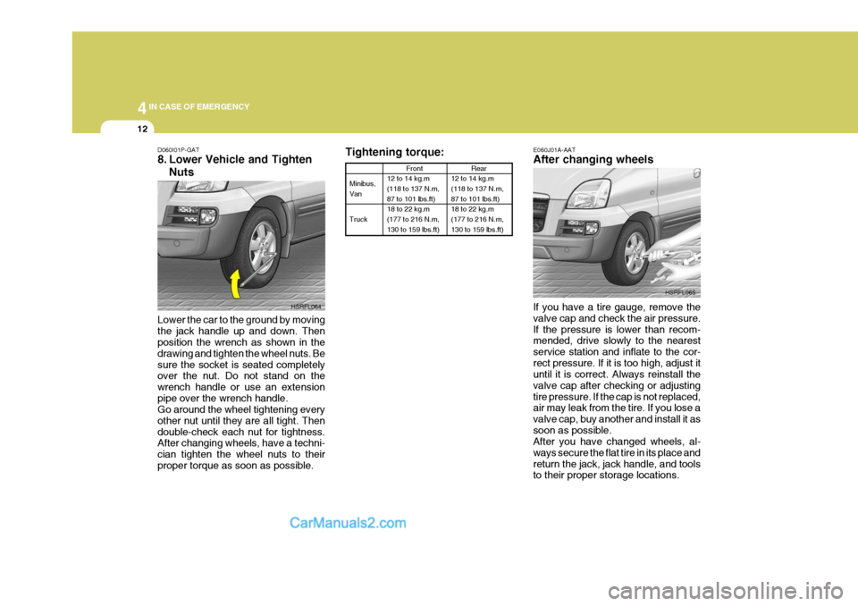
Tightening torque:
Minibus, Van Truck Front
12 to 14 kg.m (118 to 137 N.m, 87 to 101 lbs.ft) 18 to 22 kg.m(177 to 216 N.m, 130 to 159 lbs.ft)
Rear
12 to 14 kg.m (118 to 137 N.m, 87 to 101 lbs.ft) 18 to 22 kg.m(177 to 216 N.m, 130 to 159 lbs.ft)
E060J01A-AAT After changing wheels If you have a tire gauge, remove the valve cap and check the air pressure.If the pressure is lower than recom- mended, drive slowly to the nearest service station and inflate to the cor-rect pressure. If it is too high, adjust it until it is correct. Always reinstall the valve cap after checking or adjustingtire pressure. If the cap is not replaced, air may leak from the tire. If you lose a valve cap, buy another and install it assoon as possible. After you have changed wheels, al- ways secure the flat tire in its place andreturn the jack, jack handle, and tools to their proper storage locations. HSRFL065
D060I01P-GAT
8. Lower Vehicle and Tighten
Nuts
Lower the car to the ground by moving the jack handle up and down. Then position the wrench as shown in the drawing and tighten the wheel nuts. Besure the socket is seated completely over the nut. Do not stand on the wrench handle or use an extensionpipe over the wrench handle. Go around the wheel tightening every other nut until they are all tight. Thendouble-check each nut for tightness. After changing wheels, have a techni- cian tighten the wheel nuts to theirproper torque as soon as possible. HSRFL064
Page 130 of 205

4
CORROSION PREVENTION AND APPEARANCE CARE
29
4
IN CASE OF EMERGENCY
29
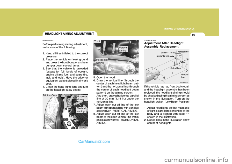
G290B03P-AAT Adjustment After Headlight Assembly Replacement If the vehicle has had front body repair and the headlight assembly has been replaced, the headlight aiming should be checked using the aiming screen asshown in the illustration. Turn on the headlight switch. (Low Beam Position)
1. Adjust headlights so that main axis
of light is parallel to center line of the body and is aligned with point "P"shown in the illustration.
2. Dotted lines in the illustration show
center of headlights.
5. Open the hood.
6. Draw the vertical line (through the
center of each headlight beam pat- tern) and the horizontal line (through the center of each headlight beam pattern) on the aiming screen.And then, draw a horizontal parallel line at 30 mm (1.18 in.) under the horizontal line.
7. Adjust each cut-off line of the low beam to the parallel line with a phillipsscrewdriver - VERTICAL AIMING.
8. Adjust each cut-off line of the low beam to the each vertical line with aphillips screwdriver - HORIZONTALAIMING.
Horizontal aiming
Verticalaiming
G290A01P-1
Truck
G290B01L
LW
H
H Cut-off line
Ground line
"P"
Horizontal line
30mm (1.18 in.) Vertical line
HEADLIGHT AIMING ADJUSTMENT
G290A03P-AAT Before performing aiming adjustment, make sure of the following.
1. Keep all tires inflated to the correct pressure.
2. Place the vehicle on level ground
and press the front bumper and rear bumper down several times.
3. See that the vehicle is unloaded
(except for full levels of coolant,engine oil and fuel, and spare tire, jack, and tools). Have the driver or equivalent weight placed in driver'sseat.
4. Clean the head lights lens and turn
on the headlight (Low beam).
Minibus/Van
G290A02P
Horizontal aiming
Verticalaiming
Page 154 of 205
6
VEHICLE MAINTENANCE REQUIREMENTS
3SCHEDULED MAINTE- NANCE REQUIREMENTS
F010E01P-AAT
Do-It-Yourself Maintenance
If you are mechanically inclined, own a few tools that are required and want to take the time to do so, you can inspect and service a number of items. Formore information about doing it your- self, see Section 8. F010F01A-GAT
A Few Tips
Whenever you have your Hyundai ser- viced, keep copies of the service records in your glovebox. This will help ensure that you can document that therequired procedures have been per- formed to keep your warranties in ef- fect. This is especially important whenservice is not performed by an autho- rized Hyundai dealer. F020A03S-GAT Inspection should be performed any time a malfunction is experienced or suspected. Receipts for all emissioncontrol system services should be re- tained to demonstrate compliance with conditions of the emissions systemwarranty.For severe usage maintenance require-ments, see page 6-11 of this section.
Page 173 of 205
8DO-IT YOURSELF MAINTENANCE
4
I010C01P-GAT DIESEL ENGINE (2.5 CRDi TCI)
1. Windshield washer fluid reservoircap
2. Engine oil filler cap
3. Brake booster 4. Brake fluid reservoir
5. Engine coolant reservoir
6. Air cleaner
7. Power steering fluid reservoir 8. Engine oil level dipstick
9. Battery
10.Fuse and relay boxI010C02P
CAUTION:
When inspecting or servic-ing the engine, you should handle tools and other heavy objects carefully sothat the plastic cover of the engine is not damaged.
!
Page 174 of 205
8
DO-IT YOURSELF MAINTENANCE
5
I011A02P-GAT
GASOLINE ENGINE (2.4 DOHC)
1. Windshield washer fluid reservoir
cap
2. Engine oil filler cap
3. Engine oil level dipstick 4. Brake booster
5. Brake fluid reservoir
6. Radiator cap
7. Air cleaner
8. Power steering oil tank
9. Battery
10.Fuse and relay boxI011A03P
CAUTION:
When inspecting or servic-ing the engine, you should handle tools and other heavy objects carefully sothat the plastic cover of the engine is not damaged.
!