Page 97 of 205

3
STARTING AND OPERATING
29
D180C01P-GAT Battery The capacity of the battery is reduced at low temperatutes.This is an inevitable result of its chemi- cal and physical properties. This is why a very cold battery, particularlyone that is not fully charged anyway, will only deliver a fraction of the starter current which is normally available.It is recommended that you have the battery checked by an authorized HYUNDAI dealer before the start ofcold weather and, if necessary, have it charged. This not only ensures reliable starting,but a battery which is kept fully charged also has a longer life. C160G02A-AAT To Keep Locks from Freezing To keep the locks from freezing, squirt an approved de-icer fluid or glycerineinto the key opening. If a lock is cov- ered with ice, squirt it with an approved de-icing fluid to remove the ice. If thelock is frozen internally, you may be able to thaw it out by using a heated key. Handle the heated key with careto avoid burning your fingers. NOTE: The proper temperature for using the immobilizer key is from -40°C to 80°C. If you heat the immobilizer key over 80°C to open the frozenlock, it may cause damage to the transponder in its head.
D180G01P-GAT Door locks To prevent the door locks from freez- ing up, the lock cylinders should be masked with tape, etc., when washingthe vehicle in cold weather to prevent the entrance of water.
D180D01P-GAT Washer fluid To ensure proper operation of the wind- shield or rear window at low tempera-tures, anti-freeze should be added to the washer fluid at a rate of one part antifreeze to one part water. D180E01P-GAT Wiper blades Before operating the wipers, check the wiper blades to confirm that they arenot frozen to the windshield or tailgate. If the blades are frozen to the wind- shield or tailgate, do not operate thewipers until the ice has melted and the blades are freed. D180F01P-GAT Ventilation slots The ventilation slots in the headlight housing on the assistant seat side should be brushed clear after a heavysnowfall so that the operation of the heating and ventilation systems will not be impaired.
Page 99 of 205

3
STARTING AND OPERATING
31LOCKING DIFFERENTIALADDITIONAL EQUIPMENT
D180M02P-GAT It is a good idea to carry a shovel or a short-handled spade in the vehicle during the winter so that you can clear away snow if you get stuck. A smallhand-brush for sweeping snow off the windscreen and rear window is also useful. D190A01HR-GAT (Minibus/van)(If Installed) A locking differential, if equipped, is for the rear wheel differential only. Thefeatures of this locking differential are described below: Just as with a conventional differential,the wheel on one side is allowed to turn at a different speed from the wheel on the other side when the vehicle iscornering. The difference between the locking differential and a conventional differential is that if the wheel on oneside of the vehicle loses traction, a greater amount of torque is applied to the rear wheel on the other side toimprove traction. NOTE: In a stationary position, the LD (Locking Differential) will operate when the difference of the revolu- tion speed between the rear rightwheel and the rear left wheel oc- curs.
CAUTION:(If installed)
White smoke may arise from thefuel fired heater outlet in the driver's front wheel housing during winterdriving. This is a normal condition. But, If a black (or gray) smoke is generated heavily, have the fuel firedheater checked by your Hyundai dealer. If the engine stops while the fuelfired heater is operating, whizzing noise may be heard from the lower of the battery in the engine com- partment. This is due to cleaning process forfuel fired heater and a normal op- eration. It will takes about 1- 3 minutes ac-cording to fuel quantity in the fuel fired heater fuel line.
!
Page 141 of 205

44IN CASE OF EMERGENCY
40FUSE PANEL DESCRIPTION
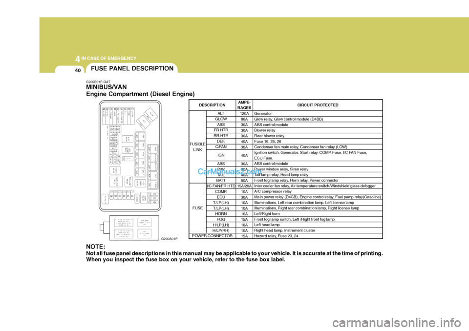
G200B01P-GAT MINIBUS/VAN Engine Compartment (Diesel Engine)
G200A01P
NOTE: Not all fuse panel descriptions in this manual may be applicable to your vehicle. It is accurate at the time of printing. When you inspect the fuse box on your vehicle, refer to the fuse box label. AMPE-
RAGES
120A80A 30A30A30A40A30A 40A30A 30A 40A 50A
15A/20A
10A30A10A 10A 10A15A 10A 10A15A CIRCUIT PROTECTED
Generator
Glow relay, Glow control module (D4BB) ABS control module
Blower relay
Rear blower relay Fuse 16, 25, 26
Condenser fan main relay, Condenser fan relay (LOW)
Ignition switch, Generator, Start relay, COMP. Fuse, I/C FAN Fuse, ECU Fuse. ABS control module
Power window relay, Siren relay
Tail lamp relay, Head lamp relay
Front fog lamp relay, Hor n relay, Power connector
Inter cooler fan relay, Air temperature switch/Windshield glass defogger
A/C compressor relay
Main power relay (D4CB), Engine control relay, Fuel pump relay(Gasoline)
Illuminations, Left rear combination lamp, Left license lamp
Illuminations, Right rear combination lamp, Right license lamp
Left/Right horn
Front fog lamp switch, Left /Right front fog lampLeft head lamp
Right head lamp, Instrument cluster
Hazard relay, Fuse 23, 24
ALT
GLOW ABS
FR HTR
RR HTR DEF.
C/FAN
IGN
ABS P/W
TAIL
BATT
I/C FAN/FR HTD COMP.
ECU
T/LP(LH) T/LP(LH) HORN
FOG
H/LP(LH)
H/LP(RH)
FUSIBLE
LINK
FUSE
DESCRIPTION
POWER CONNECTOR
Page 142 of 205

4
CORROSION PREVENTION AND APPEARANCE CARE
41
4
IN CASE OF EMERGENCY
41
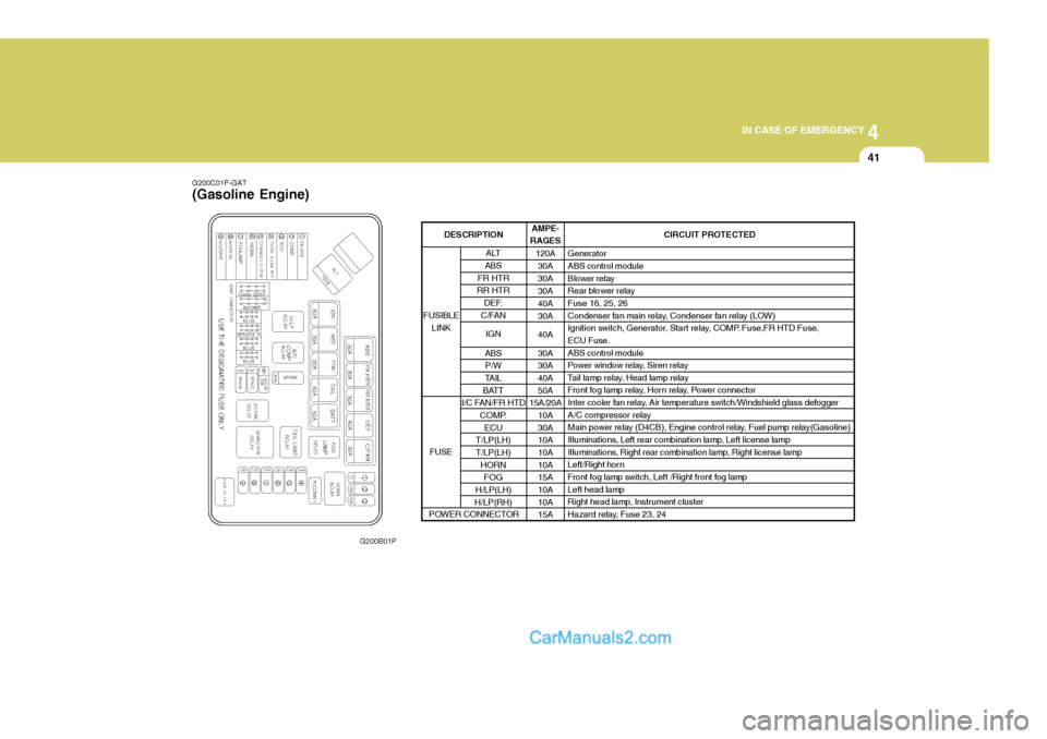
G200C01P-GAT (Gasoline Engine)
G200B01P AMPE-
RAGES
120A30A 30A30A40A30A 40A30A 30A 40A 50A
15A/20A
10A30A10A 10A 10A15A 10A 10A15A CIRCUIT PROTECTED
GeneratorABS control module
Blower relay
Rear blower relayFuse 16, 25, 26
Condenser fan main relay, Condenser fan relay (LOW)
Ignition switch, Generator, Start relay, COMP. Fuse,FR HTD Fuse,ECU Fuse. ABS control module
Power window relay, Siren relay
Tail lamp relay, Head lamp relay
Front fog lamp relay, Horn relay, Power connector
Inter cooler fan relay, Air temperature switch/Windshield glass defogger
A/C compressor relay
Main power relay (D4CB), Engine control relay, Fuel pump relay(Gasoline)
Illuminations, Left rear combination lamp, Left license lamp
Illuminations, Right rear combination lamp, Right license lamp
Left/Right horn
Front fog lamp switch, Left /Right front fog lamp Left head lamp
Right head lamp, Instrument cluster
Hazard relay, Fuse 23, 24
ALT
ABS
FR HTR
RR HTR
DEF.
C/FAN
IGN
ABS P/W
TAIL
BATT
I/C FAN/FR HTD
COMP.ECU
T/LP(LH) T/LP(LH) HORNFOG
H/LP(LH)
H/LP(RH)
FUSIBLE
LINK
FUSE
DESCRIPTION
POWER CONNECTOR
Page 143 of 205

44IN CASE OF EMERGENCY
42
G200D01P-GAT Inner Panel
G200D01PFUSE
1 23 4 56 7 8 9
10 11 12 13 14 15161718 19 20 CIRCUIT PROTECTED
Power outside mirror switch
Audio, Digital clock, Cigarette lighter, Multi-meter, A/T shift & key lock control module
Power outlet
Heater control module, Mode actuator
Front wiper & Washer
Rear wiper & Washer
Left front/rear sunroof relay, PTC heater relay, Fuel filter heater relay, Thermo sensor,
Hear lamp relay, Condenser fan main relay, HLLD switch, Inter cooler fan relay
ETACM, Power & hold switch, Front wiper relay, Seat belt tension reducer, Blower relay,
Overhead blower relay, Outside mirror defogger relay, Rear window defogger relay,
Rear blower relay, Rear blower main switch, Rear blower sub switch
Rear fog lamp relay
Seat warmer switchInstrument clusterSRS control module
ABS control module, Neutral switch, Back-up lamp switch, Vehicle speed sensor, Fuel
water sensor, Fuel filter switch, Fuel filter heater, Transaxle range switch, Instrument
cluster, TCM, Stop lamp switch, A/T shift & Key lock control module, G-Sensor, Overdrive
switch, A/T shift lever
Hazard switch
ETACM, ECM (D4BH), ECM (D4CB), Immobilizer control module, Idle-up control module
Rear window defogger relay
Left front sunroof relay
Left rear sunroof relay
Data link connector, Heater control module, Outside mirror defogger relay
Stop lamp switchAMPERAGES 10A 15A15A10A20A15A 10A 10A 10A 10A10A10A 10A10A 10A25A20A20A10A15A
Page 145 of 205
44IN CASE OF EMERGENCY
44
G200E01P-GAT TRUCK Engine Compartment
G200E01P
NOTE: Not all fuse panel descriptions in this manual may be applicable to your vehicle. It is accurate at the time of printing. When you inspect the fuse box on your vehicle, refer to the fuse box label. AMPE-
RAGES
10080 303050404030 303030 10 1015 10 1010 15 1010 20 CIRCUIT PROTECTED
Generator
Glow control
Blower control
Power window control
Fog lamp, Horn, Power connector, Fuse 13, 14, 15
Ignition switch, Star t relay, Generator
Tail lamp relay, Head lamp fuse
TCI fuse, Compressor fuse
Condenser fan ABS control moduleABS control module
Idle up fan motor relay
A/C compressor relay
Engine control relay
Left tail lamp, Illumination
Right tail lamp, Illumination
Horn
Fog lamp Left head lamp Right head lampFuse 23, 24
LABEL ALT
GLOW
HTR
P/WINDOW
BATT
IGN
TAIL A/C
C/FAN ABS.1
ABS.2
TCI
COMP ECU
TAIL (LH)
TAIL (RH)
HORN
FOG
H/LP (LH)
H/LP (RH)DESCRIP- TION
FUSIBLE LINK
FUSE
POWER CONNECTOR
Page 146 of 205

4
CORROSION PREVENTION AND APPEARANCE CARE
45
4
IN CASE OF EMERGENCY
45
G200F01P-GAT Passenger Compartment
G200F01P CIRCUIT PROTECTED
Power outside mirror switch, Cigarette lighter, Digital clock
Audio
DRL, ABS control module, condenser fan relay
Wiper motor, Washer motor
Blower relay, Head lamp relay, Power window relay, Defogger relay, Mode actuator,
Rear fog relay, Head lamp leveling switch, Heater control panel, Left (Right) head
lamp leveling actuator
ECM, Neutral switch, Injection pump, Engine control relay, Intercooler fan relay, EGR
solenoid valve, SRS control module SRS control module
Back-up lamp switch, Vehicle speed sensor, ABS relay, Instrument cluster,
Pre-excitation resistor
Hazard switch
TA C M
Instrument cluster
A/C switch
Stop lamp switch
Hazard switch Not used. Not used.Not used.
Defogger relay
Rear fog lamp relay
Left power door lock actuator Not used.
ECM, Star t relay
Digital clock, Tachograph, Power antenna, Audio
Instrument cluster, Front (Rear) room lamp, TACM, Door warning switch & Key ill.
AMPERAGES 15A 10A10A 20A 10A 10A 15A10A10A 10A10A 10A 10A10A---
10A10A15A -
10A10A 10A
FUSE
123 4 5 6 7 8 9
10 1112 13 14 1516 17 1819 20 2122 23 24
Page 147 of 205
Washing/Waxing/Polishing ........................................... 5-2
Window Glass .............................................................. 5-3
Chassis and Underbody Protection .............................. 5-3
Engine Compartment .................................................... 5-4Tire............................................................................... 5-5
5
APPEARANCE CARE
5