2005 FORD F250 SUPER DUTY brake
[x] Cancel search: brakePage 149 of 312
Bolt size Wheel lug nut torque*
lb.ft. N • m
M14 x 1.5 150 200
* Torque specifications are for nut and bolt threads free of dirt and
rust. Use only Ford recommended replacement fasteners.
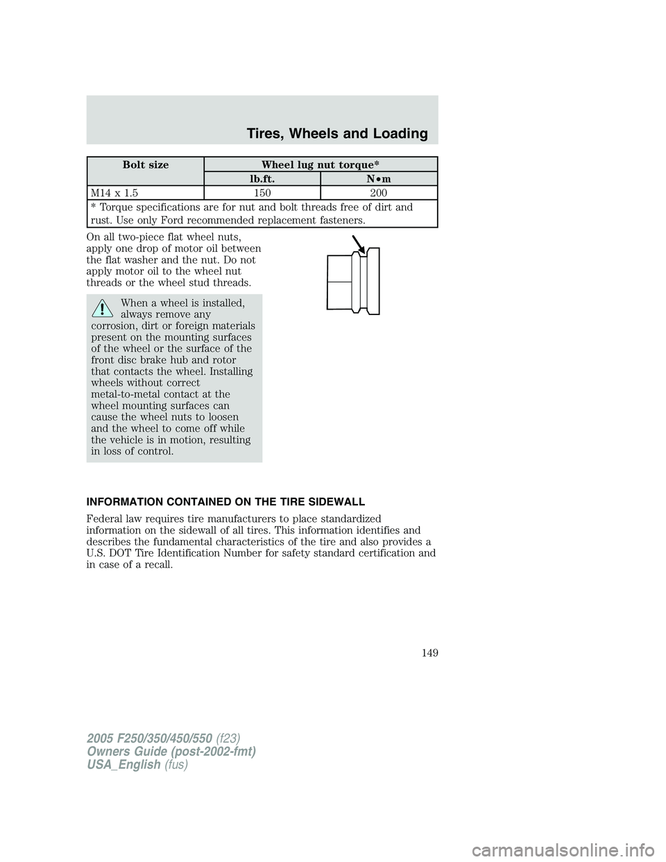
On all two-piece flat wheel nuts,
apply one drop of motor oil between
the flat washer and the nut. Do not
apply motor oil to the wheel nut
threads or the wheel stud threads.
When a wheel is installed,
always remove any
corrosion, dirt or foreign materials
present on the mounting surfaces
of the wheel or the surface of the
front disc brake hub and rotor
that contacts the wheel. Installing
wheels without correct
metal-to-metal contact at the
wheel mounting surfaces can
cause the wheel nuts to loosen
and the wheel to come off while
the vehicle is in motion, resulting
in loss of control.
INFORMATION CONTAINED ON THE TIRE SIDEWALL
Federal law requires tire manufacturers to place standardized
information on the sidewall of all tires. This information identifies and
describes the fundamental characteristics of the tire and also provides a
U.S. DOT Tire Identification Number for safety standard certification and
in case of a recall.
2005 F250/350/450/550 (f23)
Owners Guide (post-2002-fmt)
USA_English (fus) Tires, Wheels and Loading
149
Page 159 of 312
Sometimes irregular tire wear can be corrected by rotating the tires.
Note: If your tires show uneven wear ask a qualified technician at a
reputable repair facility to check for and correct any wheel misalignment,
tire imbalance or mechanical problem involved before tire rotation.
Note: Your vehicle may be equipped with a dissimilar spare tire/wheel. A
dissimilar spare tire/wheel is defined as a spare tire and/or wheel that is
different in brand, size or appearance from the road tires and wheels. If
you have a dissimilar spare tire/wheel it is intended for temporary use
only and should not be used in a tire rotation.
Note: After having your tires rotated, inflation pressure must be checked
and adjusted to the vehicle requirements.
SNOW TIRES AND CHAINS
Snow tires must be the same size and grade as the tires you
currently have on your vehicle.
Note: Do not use snow chains on front tires of Harley-Davidson vehicles.
The tires on your vehicle have all weather treads to provide traction in
rain and snow. However, in some climates, you may need to use snow
tires and chains. If you need to use chains, it is recommended that steel
wheels (of the same size and specifications) be used, as chains may chip
aluminum wheels.
Follow these guidelines when using snow tires and chains:
• Use only SAE Class S chains.
• Install chains securely, verifying that the chains do not touch any
wiring, brake lines or fuel lines.
• Drive cautiously. If you hear the chains rub or bang against your
vehicle, stop and re-tighten the chains. If this does not work, remove
the chains to prevent damage to your vehicle.
• If possible, avoid fully loading your vehicle.
• Remove the tire chains when they are no longer needed. Do not use
tire chains on dry roads.
• The suspension insulation and bumpers will help prevent vehicle
damage. Do not remove these components from your vehicle when
using snow tires and chains.
2005 F250/350/450/550 (f23)
Owners Guide (post-2002-fmt)
USA_English (fus) Tires, Wheels and Loading
159
Page 164 of 312
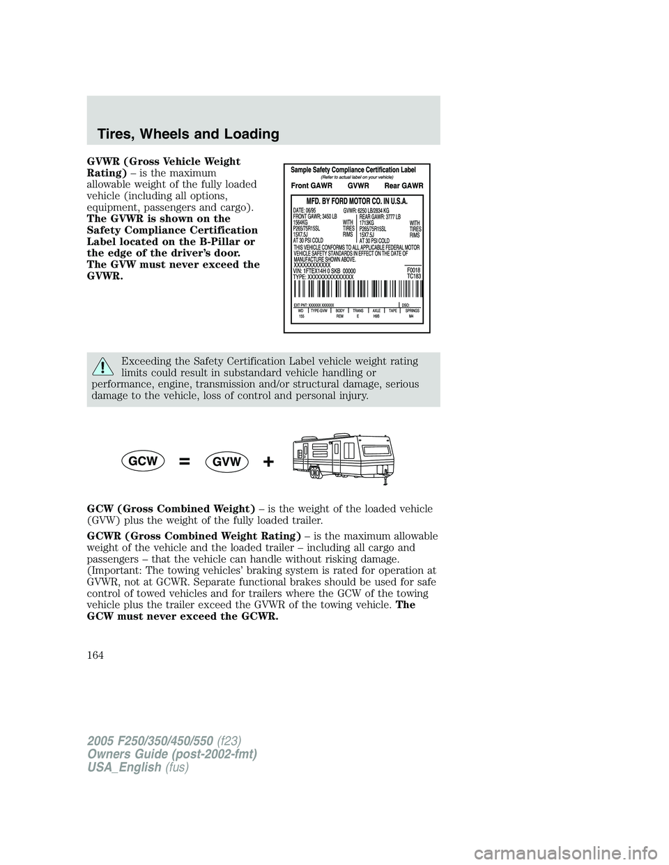
GVWR (Gross Vehicle Weight
Rating) – is the maximum
allowable weight of the fully loaded
vehicle (including all options,
equipment, passengers and cargo).
The GVWR is shown on the
Safety Compliance Certification
Label located on the B-Pillar or
the edge of the driver’s door.
The GVW must never exceed the
GVWR.
Exceeding the Safety Certification Label vehicle weight rating
limits could result in substandard vehicle handling or
performance, engine, transmission and/or structural damage, serious
damage to the vehicle, loss of control and personal injury.
GCW (Gross Combined Weight) – is the weight of the loaded vehicle
(GVW) plus the weight of the fully loaded trailer.
GCWR (Gross Combined Weight Rating) – is the maximum allowable
weight of the vehicle and the loaded trailer – including all cargo and
passengers – that the vehicle can handle without risking damage.
(Important: The towing vehicles’ braking system is rated for operation at
GVWR, not at GCWR. Separate functional brakes should be used for safe
control of towed vehicles and for trailers where the GCW of the towing
vehicle plus the trailer exceed the GVWR of the towing vehicle. The
GCW must never exceed the GCWR.
2005 F250/350/450/550 (f23)
Owners Guide (post-2002-fmt)
USA_English (fus)Tires, Wheels and Loading
164
Page 167 of 312
Special loading instructions for owners of pickup trucks and
utility-type vehicles
For important information regarding safe operation of this type
of vehicle, see the Preparing to drive your vehicle section in
the Driving chapter of this owner guide.
Loaded vehicles may handle differently than unloaded vehicles.
Extra precautions, such as slower speeds and increased stopping
distance, should be taken when driving a heavily loaded vehicle.
Your vehicle can haul more cargo and people than most passenger cars.
Depending upon the type and placement of the load, hauling cargo and
people may raise the center of gravity of the vehicle.
TRAILER TOWING
Your vehicle may tow a Conventional/Class IV trailer or fifth wheel trailer
provided the maximum trailer weight is less than or equal to the
maximum trailer weight listed for your engine and rear axle ratio on the
following charts.
To calculate your maximum trailer weight:
for pickup trucks take curb weight, hitch hardware, and the driver’s
weight, and substract them from the GCWR listed for your vehice in the
following chart/table given its series, engine, transmission and drive axle
ration. This calculation will give you the maximum trailer weight possible
for your vehicle.
for chassis cabs and pickup trucks with aftermarket equipment:
weigh your vehicle at a certified scale and subtract this actual curb
weight, hitch hardware, and the driver’s weight from the GCWR listed for
your vehicle in the following chart/table given its series, engine,
transmission and drive axle ratio. This calculation will give you the
maximum trailer weight possible for your vehicle.
The weight of all additional cargo, passengers and payload must be
subtracted from the maximum trailer weight calculated above.
Further trailer/hitch restrictions and limitations exist depending on the
type of trailer and hitch used. These additional maximum trailer weight
and tongue load limitations are listed in the chart/table that follows the
listing of GCWRs.
Towing a trailer places an additional load on your vehicle’s engine,
transmission, axle, brakes, tires and suspension. Inspect these
2005 F250/350/450/550 (f23)
Owners Guide (post-2002-fmt)
USA_English (fus) Tires, Wheels and Loading
167
Page 170 of 312
Towing trailers beyond the maximum tongue weight exceeds the
limit of the towing system and could result in vehicle structural
damage, loss of vehicle control and personal injury.
Load equalizing hitch
When hooking up a trailer using a load equalizing hitch, always use the
following procedure:
1. Park the unloaded vehicle on a level surface. With the ignition on and
all doors closed, allow the vehicle to stand for several minutes so that it
can level.
2. Measure the height of a reference point on the front and rear bumpers
at the center of the vehicle.
3. Attach the trailer to the vehicle and adjust the hitch equalizers so that
the front bumper height is within 1
� 2
” (13 mm) of the reference point.
After proper adjustment, the rear bumper should be no higher than in
Step 2.
Note: Adjusting an equalizing hitch so the rear bumper of the vehicle is
higher than it was unloaded will defeat the function of the load
equalizing hitch and may cause unpredictable handling.
Safety chains
Always connect the trailer’s safety chains to the frame or hook retainers
of the vehicle hitch. To connect the trailer’s safety chains, cross the
chains under the trailer tongue and allow slack for turning corners.
If you use a rental trailer, follow the instructions that the rental agency
gives to you.
Do not attach safety chains to the bumper.
Trailer brakes
Electric brakes and manual, automatic or surge-type trailer brakes are
safe if installed properly and adjusted to the manufacturer’s
specifications. The trailer brakes must meet local and Federal
regulations.
If you own a trailer with a hydraulic brake system, do not
connect the trailer’s hydraulic brake system directly to your
vehicle’s brake system. The vehicle’s brake system is only designed to
carry the appropriate amount of brake fluid for the vehicle alone.
Connecting a hydraulic trailer braking system could adversely affect
your vehicle’s braking performance.
2005 F250/350/450/550 (f23)
Owners Guide (post-2002-fmt)
USA_English (fus)Tires, Wheels and Loading
170
Page 171 of 312
The braking system of the tow vehicle is rated for operation at the
GVWR not GCWR.
Integrated trailer brake controller (if equipped)
Your vehicle may be equipped with a fully integrated electronic Trailer
Brake Controller (TBC). When used properly, the TBC helps assure
smooth and effective trailer braking by powering the trailer’s electric
brakes with a proportional output based on the towing vehicle’s brake
pressure.
The Ford TBC can only be used with trailers having
electric-actuated drum brakes (one to four axles) and not
hydraulic surge or electric-over-hydraulic types. It is the responsibility
of the customer to ensure that the trailer brakes are adjusted
appropriately, functioning normally and all electric connections are
properly made.
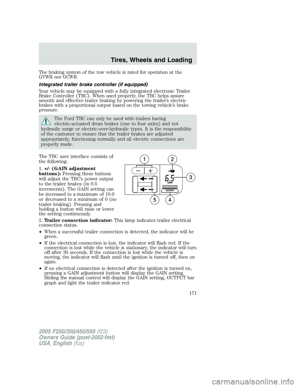
The TBC user interface consists of
the following:
1. +/- (GAIN adjustment
buttons): Pressing these buttons
will adjust the TBC’s power output
to the trailer brakes (in 0.5
increments). The GAIN setting can
be increased to a maximum of 10.0
or decreased to a minimum of 0 (no
trailer braking). Pressing and
holding a button will raise or lower
the setting continuously.
2. Trailer connection indicator: This lamp indicates trailer electrical
connection status.
• When a successful trailer connection is detected, the indicator will be
green.
• If the electrical connection is lost, the indicator will flash red. If the
connection is lost while the vehicle is stationary, the indicator will turn
off after 30 seconds. If the connection is lost while the vehicle is
moving, the indicator will flash until the ignition is turned off, then on
again.
• If no electrical connection is detected after the ignition is turned on,
pressing a GAIN adjustment button will display the GAIN setting.
Sliding the manual control will display the GAIN setting, OUTPUT bar
graph and light the trailer indicator red.
2005 F250/350/450/550 (f23)
Owners Guide (post-2002-fmt)
USA_English (fus) Tires, Wheels and Loading
171
Page 172 of 312
3. GAIN setting display: Shows the current GAIN setting. This will
illuminate when a trailer is connected, flash if the trailer becomes
disconnected, or remain off if no trailer is connected.
4. OUTPUT bar graph: When the vehicle’s brake pedal is pushed, or
when the manual control is activated, green bar indicators will illuminate
to indicate the amount of power going to the trailer brakes relative to
the brake pedal or manual control input.
5. Manual control lever: Slide the control lever to the left to activate
power to the trailer’s electric brakes independent of the tow vehicle’s
brakes (see the following Procedure for adjusting GAIN section for
instructions on proper use of this feature). If the manual control is
activated while the brake is also applied the greater of the two inputs
determines the power sent to the trailer brakes.
• Stop Lamps: Activating the TBC manual control lever will illuminate
both the trailer brake lamps and the tow vehicle brake lamps
(presuming proper trailer electrical connection). Pressing the vehicle
brake pedal will also illuminate both trailer and vehicle brake lamps.
GAIN
The GAIN setting is used to set the TBC for the specific towing
condition and should be changed as towing conditions change. Changes
to towing conditions include trailer load, vehicle load, road conditions
and weather.
The GAIN should be set to provide the maximum trailer braking
assistance while ensuring the trailer wheels do not lock when braking.
Locked trailer wheels may lead to trailer instability.
Procedure for adjusting GAIN:
Note: This should only be performed in a traffic free environment at
speeds of approximately 20 – 25 mph (30 – 40 km/h).
1. Make sure the trailer brakes are in good working condition,
functioning normally, and properly adjusted. See your trailer dealer if
necessary.
2. Hook-up the trailer and make the electrical connections according to
the trailer manufacturer’s instructions.
3. When a trailer with electric brakes is plugged in, the trailer connection
indicator will illuminate green on the TBC and the GAIN setting display
will illuminate.
4. Use the GAIN adjustment (+/-) buttons to increase or decrease the
GAIN setting to the desired starting point. (A GAIN setting of 6.0 is a
good starting point for heavier loads.)
2005 F250/350/450/550 (f23)
Owners Guide (post-2002-fmt)
USA_English (fus)Tires, Wheels and Loading
172
Page 173 of 312
5. In a traffic-free environment, tow the trailer on a dry, level surface at
a speed of 20 – 25 mph (30 – 40 km/h) and squeeze the manual control
lever completely.
6. If the trailer wheels lock-up (indicated by squealing tires), reduce the
GAIN setting; if the trailer wheels turn freely, increase the GAIN setting.
Repeat Steps 5 and 6 until the GAIN setting is at a point just below
trailer wheel lock-up. If towing a heavier trailer, trailer wheel lockup may
not be attainable even with the maximum GAIN setting of 10.
Explanation of instrument cluster messages:
The TBC interacts with the instrument cluster message center. These
messages, accompanied by a single chime, will be displayed when the
TBC determines a malfunction in the trailer connection, TBC system, or
in the trailer. These messages are listed below:
TRAILER DISCONNECTED (if equipped with message center) or
CHECK TRAILER (if equipped with mini message center): This
message is displayed when a trailer connection was determined and then
a disconnection, either intentionally or unintentionally, has been sensed
during a given ignition cycle. This message is also displayed during
manual activation without a trailer connected.
TBC FAULT: This message is displayed in response to faults sensed by
the TBC. In the event this message is seen, please take your vehicle to
an authorized Ford dealership for diagnosis and repair. The TBC may still
function, but performance may be degraded.
TRAILER FAULT: The TBC is capable of determining certain faults in
the vehicle wiring and trailer wiring/brake system. This message is
displayed when one of the following faults has occurred:
• Short circuit on the electric brake output wire: If the TRAILER
FAULT message is displayed with no trailer connected, the problem is
with the vehicle wiring from the TBC to the 7–pin connector in the
bumper. If the message is only displayed with a trailer connected, the
problem is related to the trailer wiring; consult your trailer dealer for
assistance.
• Trailer brake overload: The trailer brakes are drawing too much
current; consult your trailer dealer for assistance.
Note: Your TBC can be diagnosed by your authorized Ford dealership to
determine exactly which trailer fault has occurred; however, if the fault
is with the trailer this diagnosis is not covered under your Ford
warranty.
2005 F250/350/450/550 (f23)
Owners Guide (post-2002-fmt)
USA_English (fus) Tires, Wheels and Loading
173