Page 82 of 258
81GETTING TO KNOW YOUR VEHICLE
REAR DOUBLE DOORS
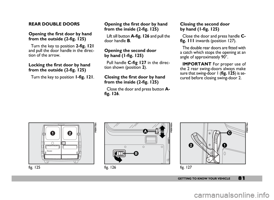
Opening the first door by hand
from the outside (2-fig. 125)
Turn the key to position 2-fig. 121
and pull the door handle in the direc-
tion of the arrow.
Locking the first door by hand
from the outside (2-fig. 125)
Turn the key to position 1-fig. 121.
fig. 125
F0D0178m
Opening the first door by hand
from the inside (2-fig. 125)
Lift sill button A-fig. 126and pull the
door handle B.
Opening the second door
by hand (1-fig. 125)
Pull handle C-fig 127in the direc-
tion shown (position2).
Closing the first door by hand
from the inside (2-fig. 125)
Close the door and press button A-
fig. 126.Closing the second door
by hand (1-fig. 125)
Close the door and press handle C-
fig. 111inwards (position 127).
The double rear doors are fitted with
a catch which stops the opening at an
angle of approximately 90°.
IMPORTANTFor proper use of
the 2 rear swing-doors always make
sure that swing-door 1 (fig. 125) is se-
cured before closing swing-door 2.
fig. 127
F0D0179m
fig. 126
F0D0162m
Page 83 of 258
82GETTING TO KNOW YOUR VEHICLE
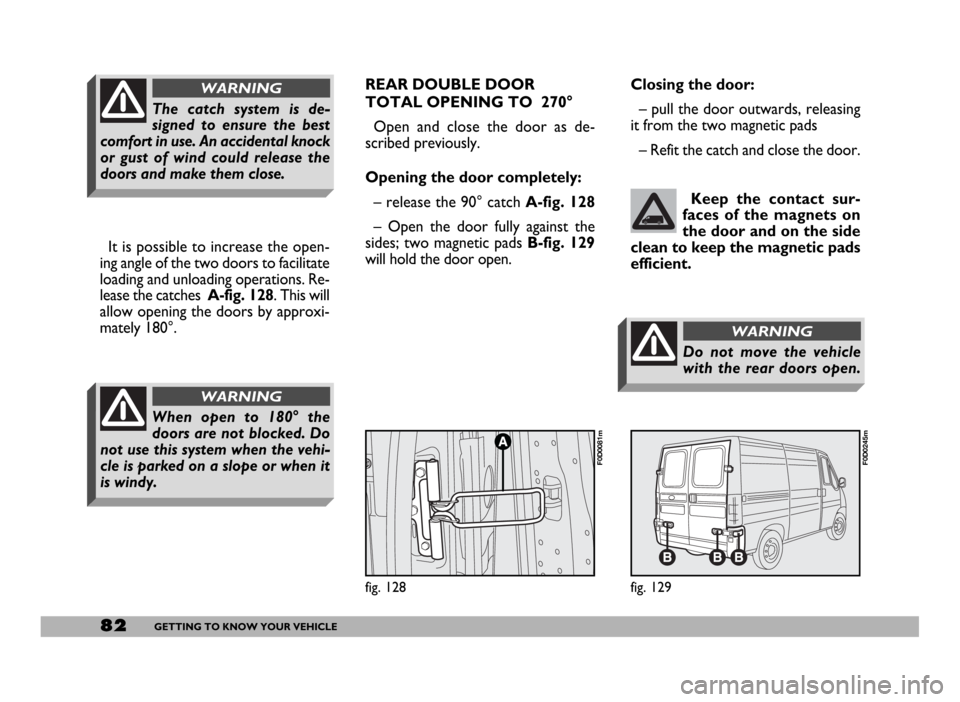
It is possible to increase the open-
ing angle of the two doors to facilitate
loading and unloading operations. Re-
lease the catches A-fig. 128. This will
allow opening the doors by approxi-
mately 180°.
When open to 180° the
doors are not blocked. Do
not use this system when the vehi-
cle is parked on a slope or when it
is windy.
WARNING
The catch system is de-
signed to ensure the best
comfort in use. An accidental knock
or gust of wind could release the
doors and make them close.
WARNINGREAR DOUBLE DOOR
TOTAL OPENING TO 270°
Open and close the door as de-
scribed previously.
Opening the door completely:
– release the 90° catch A-fig. 128
– Open the door fully against the
sides; two magnetic pads B-fig. 129
will hold the door open. Closing the door:
– pull the door outwards, releasing
it from the two magnetic pads
– Refit the catch and close the door.
Keep the contact sur-
faces of the magnets on
the door and on the side
clean to keep the magnetic pads
efficient.
fig. 129
F0D0245m
fig. 128
F0D0081m
Do not move the vehicle
with the rear doors open.
WARNING
Page 84 of 258
83GETTING TO KNOW YOUR VEHICLE
CENTRAL DOOR LOCKING
IMPORTANTCentral door locking
is active on all doors if front doors (cab
doors) are used for opening/closing.
When operating one of the rear or
side door lock, only that door will be
locked/unlocked.
From the outside
When the doors are closed, insert
and turn the key in the lock of one of
the driver’s cab doors.
From the inside
When the doors are closed, press
(to lock) or lift (to unlock) one of the
driver’s cab door safety sill buttons.
IMPORTANT If one of the cab
doors is not shut properly or there is
a failure in the system, the central
locking feature will not work and, af-
ter some attempts, the device will stop
working for about 2 minutes. In these
two minutes, the doors can be locked
or unlocked manually without the
electrical system coming into play.After the two minutes, the control
unit is ready to receive commands
once more. If the reason for the mal-
functioning has been removed, the de-
vice will start to work properly again.
If not, it will cut once more.
FRONT DOOR WINDOW
REGULATORS
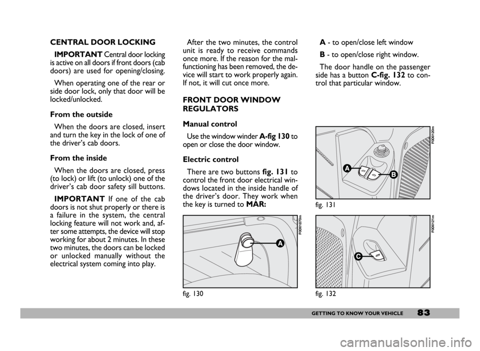
Manual control
Use the window winderA-fig 130to
open or close the door window.
Electric control
There are two buttons fig. 131to
control the front door electrical win-
dows located in the inside handle of
the driver’s door. They work when
the key is turned to MAR:A- to open/close left window
B- to open/close right window.
The door handle on the passenger
side has a button C-fig. 132to con-
trol that particular window.
fig. 130
F0D01870m
fig. 131
F0D0120m
fig. 132
F0D0121m
Page 93 of 258

92GETTING TO KNOW YOUR VEHICLE
SIDE BAGS fig. 142
The purpose of the side bag is to
protect the front seat passenger’s
chest in the event of a side impact of
medium to high degree.
The device consists of a bag housed
in the front seat backs which imme-
diately inflates. This solution ensures
that the bag is in an optimal position
regardless of the seat position.
In the event of a side impact, the con-
trol unit processes the signals from a
deceleration sensor and fires the side
bag.
The bag inflates instantly and acts as
a soft protective barrier between the
front seat passenger’s chest and vehi-
cle door. The bag deflates immediate-
ly afterwards.
fig. 142
F0D0042m
fig. 140
F0D0163m
Manual deactivation
Should it be absolutely necessary to
carry a child on the front seat, the pas-
senger’s airbag can be deactivated.
Deactivation/reactivation takes place
with ignition key at STOPand oper-
ating it in the special key switch on the
left side of the tachograph.
IMPORTANTOperate the switch
only when the engine is not running
and the ignition key is removed.The key-operated switch (A-
fig. 140) has two positions:
– front passenger’s airbag on (posi-
tion ON
P): instrument panel warn-
ing light off F; it is absolutely pro-
hibited to carry a child on the front
seat.
– front passenger’s airbag off (posi-
tion OFF F): instrument panel
warning light on F; it is possible to
carry a child protected by special re-
straint system on the front seat.
The instrument panel warning light
F(B-fig. 141) stays on permanent-
ly until the passenger’s airbag is reac-
tivated.
Deactivation of the front passenger’s
airbag does not inhibit operation of
the side airbag.
fig. 141
F0D0227m
Page 94 of 258
93GETTING TO KNOW YOUR VEHICLE
In the event of low speed side colli-
sions (for which seat belts are suffi-
cient protection), the airbag is not trig-
gered. Also in this case, it is important
to wear seat belts at all times. This will
ensure correct positioning of the pas-
senger and prevent being projected
from the vehicle in the event of very
violent crashes.
The side bag (driver and passenger)
is therefore not a replacement of but
is complementary to the use of belts,
which should always be worn, as spec-
ified by law in Europe and most non-
European countries.GENERAL WARNINGS
The front and/or side airbags
may be deployed if the vehicle is
subject to heavy knocks or acci-
dents involving the underbody
area, such as for example violent
shocks against steps, kerbs or low
obstacles, falling of the vehicle in
big holes or sags in the road.
Triggering of the airbags re-
leases a small amount of powder.
This powder is not harmful and
does not indicate the start of fire.
The unfold cushion surface and
the vehicle interiors could be cov-
ered by dusty remains: this dust
could irritate skin and eyes. In
case of contact, wash yourself us-
ing neutral soap and water.The airbag system has a validity
of 14 years as to the pyrotechnic
charge and 10 years as to the coil
contact (see the plate set on the
left front door post near hinges).
As these dates approach, con-
tact Fiat Dealership for replace-
ment.
If an accident has triggered the
airbag, contact a Fiat Dealership
so that the whole safety device,
electronic control unit, belt, pre-
tensioners can be replaced and
have the electric system checked
over.
All control, repair and replace-
ment operations concerning the
airbags must only be carried out
at a Fiat Dealership.
If you are having the vehicle
scrapped, have the airbag system
deactivated at a Fiat Dealership
first.
Page 99 of 258
98GETTING TO KNOW YOUR VEHICLE
SOUND SYSTEM
Visit a Fiat Dealership if
you want to fit a sound
system after buying the
vehicle. They can advise you on
how to safeguard battery life. Ex-
cessive idle intake can damage
the battery and may invalidate
the warranty.LIGHT SET-UP
The system consists of:
– radio power supply cables
– dashboard front speaker cables
– housing for the radio
– aerial and relevant wire
HEAVY SET-UP
The system consists of:
– radio power supply cables
– dashboard front speaker cables
– dashboard speakers
– door speaker cables
– door speakers
– housing for the radio
– aerial and relevant wire.
fig. 145
F0D0171m
For the Panorama version, four ad-
ditional speakers are provided, two on
the right and two on the left side, set
one in the body side and the other on
the top of the pillar.
For the Combi version, two addi-
tional rear speakers are provided, one
per body side.
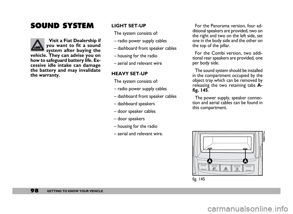
The sound system should be installed
in the compartment occupied by the
object tray which can be removed by
releasing the two retaining tabs A-
fig. 145.
The power supply, speaker connec-
tion and aerial cables can be found in
this compartment.
Page 100 of 258
99GETTING TO KNOW YOUR VEHICLE
IMPORTANT The cables are se-
cured to the heater cables bundle with
adhesive tape to cut out noise.
For speakers, use the housings at the
ends of the dashboard fig. 146:
A- left-hand speaker housing
B- right-hand speaker housing.
To install: dismantle the press-fitted
dashboard panel and insert the speak-
er in its special recess.
To fit speakers in the doors, loosen
screws A-fig. 147and remove the
protection grid. After securing the
speakers refit the protecting grid.
fig. 146
F0D0061m
SOUND SYSTEM (optional)
The complete system consists of:
– system set-up (see previous para-
graph)
– sound system (radio with cassette
or CD player) with removable front
panel (for features and operation, see
the attached “Sound system” supple-
ment).
fig. 147
F0D0060m
The wiring diagram is as follows
(fig. 148):
Connector A
A1Vehicle speed
A2Booster
A3Spare
A4Key-controlled power (+15)
A5Aerial power
A6Light
A7Power + (battery)
A8Ground
fig. 148
F0D0672m
Page 101 of 258

100GETTING TO KNOW YOUR VEHICLE
The wiring connection diagram is:
1Sound system MUTE function.
2Spare.
3Cellular phone INPUT ground
signal (–).
4Cellular phone INPUT ground
signal (+).
5Spare
6Spare
7Ignition switch power (+15).
8Spare
9Battery power (+).
10Ground.
Max. aerial power is 20W.
WARNINGConnector B
B1Door speaker
passenger’s side (+)
B2Door speaker
passenger’s side (-)
B3Dashboard speaker
right side (+)
B4Dashboard speaker
right side (-)
B5Dashboard speaker
left side (+)
B6Dashboard speaker
left side (-)
B7Door speaker
driver’s side (+)
B8Door speaker
driver’s side (-)
AERIAL
Aerial is built into the passenger’s
door mirror.CELLULAR PHONE
SET-UP
IMPORTANTThe optional cellu-
lar phone set-up is bound to “Heavy
set-up” or “Radio” purchase.
The system set-up consists of:
– dual-purpose aerial (sound system
+ cellular phone), built into the pas-
senger’s door mirror;
– dual-purpose aerial connection
wires and ten-pin connector wiring
fig. 149;
– front door speakers.
fig. 149
F0D0106m
See the information given
in the “Accessory installa-
tion” section when making electri-
cal connections so as not to dam-
age the system.
WARNING