Page 45 of 258

44GETTING TO KNOW YOUR VEHICLE
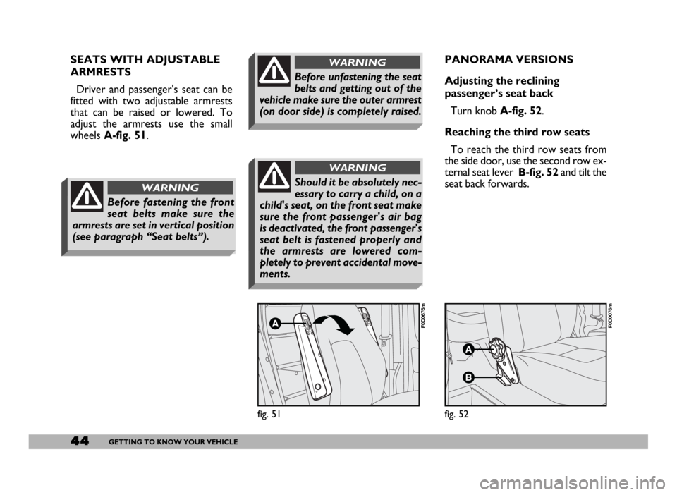
PANORAMA VERSIONS
Adjusting the reclining
passenger’s seat back
Turn knobA-fig. 52.
Reaching the third row seats
To reach the third row seats from
the side door, use the second row ex-
ternal seat lever B-fig. 52and tilt the
seat back forwards.
fig. 52
F0D0076m
SEATS WITH ADJUSTABLE
ARMRESTS
Driver and passenger's seat can be
fitted with two adjustable armrests
that can be raised or lowered. To
adjust the armrests use the small
wheels A-fig. 51.
fig. 51
F0D0676m
Should it be absolutely nec-
essary to carry a child, on a
child's seat, on the front seat make
sure the front passenger's air bag
is deactivated, the front passenger's
seat belt is fastened properly and
the armrests are lowered com-
pletely to prevent accidental move-
ments.
WARNING
Before fastening the front
seat belts make sure the
armrests are set in vertical position
(see paragraph “Seat belts”).
WARNING
Before unfastening the seat
belts and getting out of the
vehicle make sure the outer armrest
(on door side) is completely raised.
WARNING
Page 47 of 258
46GETTING TO KNOW YOUR VEHICLE
Adjusting the seat back angle
Use button A-fig. 56.
Height adjustment
Use button C-fig. 56to raise/low-
er the seat.
Moving the seat backwards
or forwards
Lift lever D-fig. 56and push the seat
backwards or forwards.
fig. 56
F0D0276m
Revolving the seat
To rotate the seat proceed as fol-
lows:
– lower the seat forward complete-
ly;
– set the seat fully backwards;
– set the seat back in straight posi-
tion;
– press button B-fig. 56to rotate
the seat.
From the normal position of use the
seat can be turned 30° towards the
door (i.e.: towards the outside of the
vehicle) as shown in fig. 57and 210°
towards the inside of the vehicle as
shown in fig. 58.
fig. 57
F0D0294m
fig. 58
F0D0297m
When travelling, the re-
volving seats shall always
be set in running direction (i.e.: fac-
ing forward).
WARNING
Page 53 of 258
52GETTING TO KNOW YOUR VEHICLE
fig. 73
F0D0048m
fig. 74
F0D0041m
If the mirror makes it
difficult to get through
narrow gaps, fold it from
position 1 to position 2.
Electrical adjustment
The mirrors can only be adjusted
electrically when the key is at MAR.
To adjust the mirror, turn knob B-
fig. 74to one of the following four po-
sitions: Í1left mirror, È2right mir-
ror, Î3left wide-angle, Ï4right
wide-angle
Once the knob has been positioned,
move it in the direction indicated by
the arrows to adjust the reflecting sur-
face of the selected mirror.
The reflecting surface of
the lower part of the mirror
is parabolic to increase the range.
Consequently, the dimension of the
reflected image is reduced, giving
the impression that the object is
more distant than it is in fact.
WARNING
DOOR MIRRORS
Manual adjustment
Adjust each of the two mirrors
A-fig. 73.IMPORTANTRadio aerial (or ra-
dio aerial + cellular telephone + GPS)
is built into the passenger’s door mir-
ror.
Page 72 of 258

71GETTING TO KNOW YOUR VEHICLE
CONTROLS
CENTRAL BUTTON PANEL
fig. 103
A- Heated rear window on/off
(where provided)
When the heated rear window is
switched on, also the door mirror de-
frosting function is activated. It is how-
ever possible to activate the defrost-
ing function without switching on the
heated rear window: the control but-
ton is the same.
B - Front fog lights on/off
C- Hazard lights on/off
CEILING LIGHT
The lights come on automatically
when a front door is opened.
Press button A-fig. 101to switch
both lights on with the doors closed
or open.
Press button Cto light the right lamp
only. Press button Bto light the left
lamp only.
A second ceiling light can be found
over the rear door in the load com-
partment. Press the short side of the
plastic lens as shown in fig. 102to
switch this light on.
fig. 101
F0D0037m
fig. 102
F0D0038m
In the event of defective
device operation or unsuc-
cessful operation, press button
OFF and contact the Fiat Dealer-
ship after checking the protection
fuse well-being. Deactivate the de-
vice when you are not using it to
prevent accidental speed memori-
sation.
WARNING
fig. 103
F0D0032m
Page 75 of 258
74GETTING TO KNOW YOUR VEHICLE
The central dashboard is fitted with
bottle holder fig. 109.In versions with three seats in the cab,
a grid container for small objects or pa-
pers can be found under the passen-
ger’s bench seat fig. 110.
Pockets and an additional bottle
holder can be found on the door pan-
els.
WRITING/READING DESK
In the middle of the dashboard,
above the sound system compart-
ment, is fitted a mobile writing desk
A-fig. 111that can be used as a read-
ing desk by lifting the rear part and
then resting the proper support on
the dashboard B.
fig. 109
F0D0054m
fig. 110
F0D0079m
fig. 111
F0D0055m
IMPORTANTNever use the writ-
ing desk in vertical position when trav-
elling.
In the cab, with double passenger
seat it is possible to have a special
desk.
It is contained in the upper part of
the central seat backrest; to tilt it
move band A - fig. 112and pull the
backrest forwards.
Clip Bis to be used to hold sheets/
papers.
fig. 112
F0D0225m
Page 77 of 258

76GETTING TO KNOW YOUR VEHICLE
IMPORTANTWith the engine off
and the ignition key at MAR, pro-
longed use (e.g.: for more than an
hour) of accessories with high current
intake could deploy the battery, even
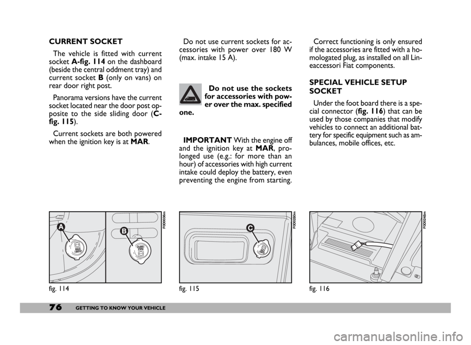
preventing the engine from starting. CURRENT SOCKET
The vehicle is fitted with current
socket A-fig. 114on the dashboard
(beside the central oddment tray) and
current socket B(only on vans) on
rear door right post.
Panorama versions have the current
socket located near the door post op-
posite to the side sliding door (C-
fig. 115).
Current sockets are both powered
when the ignition key is at MAR.
fig. 116
F0D0248m
Do not use the sockets
for accessories with pow-
er over the max. specified
one.
fig. 114
F0D0036m
Correct functioning is only ensured
if the accessories are fitted with a ho-
mologated plug, as installed on all Lin-
eaccessori Fiat components.
SPECIAL VEHICLE SETUP
SOCKET
Under the foot board there is a spe-
cial connector (fig. 116) that can be
used by those companies that modify
vehicles to connect an additional bat-
tery for specific equipment such as am-
bulances, mobile offices, etc. Do not use current sockets for ac-
cessories with power over 180 W
(max. intake 15 A).
fig. 115
F0D0280m
Page 80 of 258

79GETTING TO KNOW YOUR VEHICLE
IMPORTANT NOTES
Do not use abrasive detergents or
solvents to clean the device. To clean
its external surface, use a wet cloth or
special products for cleaning synthet-
ic materials.
The multimeter is installed and
sealed with lead by authorised per-
sonnel: access to the device and rele-
vant power and recording cables is
forbidden.
The vehicle owner is responsible for
governing the instrument use. The in-
spection must be carried out at least
every two years and will include a test
to confirm correct operation.
After the inspection, check that the
plate is updated with specified data.DRIVER’S CAB DOORS
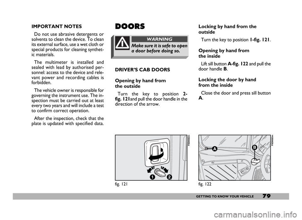
Opening by hand from
the outside
Turn the key to position 2-
fig. 121and pull the door handle in the
direction of the arrow.DOORS
Make sure it is safe to open
a door before doing so.
WARNING
Locking by hand from the
outside
Turn the key to position 1-fig. 121.
Opening by hand from
the inside
Lift sill button A-fig. 122and pull the
door handle B.
Locking the door by hand
from the inside
Close the door and press sill button
A.
fig. 121
F0D0082m
fig. 122
F0D0083m
Page 81 of 258

80GETTING TO KNOW YOUR VEHICLE
SIDE SLIDING DOOR
When leaving the vehicle
parked with the sliding
doors open, always check that the
door hooks are properly fastened
into the retaining device.
WARNING
fig. 123
F0D0084m
Do not move the vehicle
with side doors open.
WARNING
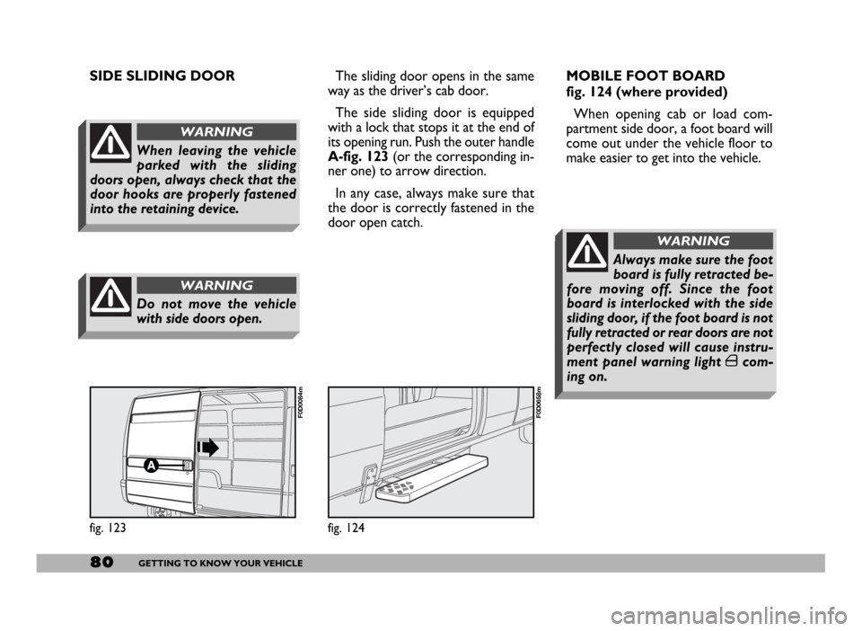
The sliding door opens in the same
way as the driver’s cab door.
The side sliding door is equipped
with a lock that stops it at the end of
its opening run. Push the outer handle
A-fig. 123(or the corresponding in-
ner one) to arrow direction.
In any case, always make sure that
the door is correctly fastened in the
door open catch.
fig. 124
F0D0658m
MOBILE FOOT BOARD
fig. 124 (where provided)
When opening cab or load com-
partment side door, a foot board will
come out under the vehicle floor to
make easier to get into the vehicle.
Always make sure the foot
board is fully retracted be-
fore moving off. Since the foot
board is interlocked with the side
sliding door, if the foot board is not
fully retracted or rear doors are not
perfectly closed will cause instru-
ment panel warning light ´com-
ing on.
WARNING