2005 FIAT DUCATO 244 Power
[x] Cancel search: PowerPage 8 of 258

7GETTING TO KNOW YOUR VEHICLE
SYMBOLS
Special coloured labels have been at-
tached near or actually on some of
the components of your Ducato.
These labels bear symbols that remind
you of the precautions to be taken as
regards that particular component.KEYS fig. 3
The following keys are provided with
the vehicle:
– two keys Awith metal insert and
power-assisted opening if the vehicle
is not equipped with remote control;
– key Aand key Bif the vehicle is fit-
ted with a door lock remote control.
– Key Ais the key that is used nor-
mally. It will:
– start the engine;
– lock/unlock the front doors;
– lock/unlock the side sliding doors;
– lock/unlock the rear doors;
– lock/unlock the fuel filler cap.
fig. 3
F0D0128m
THE FIAT CODE
SYSTEM
To further protect your vehicle from
theft, it has been fitted with an engine
immobiliser system (Fiat CODE)
which is automatically activated when
the ignition key is removed.
An electronic device, in fact, is fitted
in each ignition key grip. The device
modulates a signal when the engine is
started through a special aerial built
into the ignition switch. The modulate
signal, which changes each time the
engine is started, is the password by
means of which the control unit
recognises the key and enables to
start the engine.
Page 10 of 258

9GETTING TO KNOW YOUR VEHICLE
DUPLICATE KEYS
When additional keys are required,
go to your Fiat Dealership, taking all
the keys in your possession and the
CODE card with you. The Fiat Deal-
ershipwill store the old and new keys
(up to eight) in the system. The Fiat
Dealershipmay ask you to demon-
strate that you own the vehicle.
The codes of any keys that are not
available when the new storage pro-
cedure is carried out will be deleted
from the memory to prevent any lost
or stolen keys being used to start the
engine.
All the keys and the CODE card
must be handed over to the new own-
er when selling the vehicle.DOOR LOCK
REMOTE CONTROL
The radio-frequency remote control
is built into the ignition key.
The key fig. 6includes the following:
– a metal insert Athat can be en-
closed in the key grip
– a button Efor power-assisted
opening of the metal insert
– a button Cfor remote door un-
locking and electronic alarm deactiva-
tion (where provided) at the same
time, and timed switching on of the in-
ternal ceiling lights;
– a button Dfor remote door lock-
ing and electronic alarm activation
(where provided) at the same time,
and switching off of the internal ceiling
lights;
– led Bindicating control sending to
electronic alarm system receiver. If you are still unable to start the en-
gine, perform the emergency start-up
procedure (see “In an emergency”)
and call your Fiat Dealership.
When the vehicle is travelling and the
key is at MAR:
1)If the Ywarning light comes on
while the vehicle is moving, this means
that the system is running a self-test
(e.g. due to a voltage drop).
2)If the Ywarning light flashes, the
vehicle is not protected by the engine
immobiliser. Contact a Fiat Dealer-
shipimmediately and get them to
store the codes of all the keys in the
memory.
IMPORTANTThe electronic com-
ponents inside the key may be dam-
aged if the key is subjected to sharp
knocks.
IMPORTANTEach key provided
with the vehicle has its own code, dif-
ferent from all the others, which must
be stored in the memory of the sys-
tem control unit.
Page 14 of 258

13GETTING TO KNOW YOUR VEHICLE
SYSTEM SELF-TEST
If the beep is followed after one sec-
ond by another beep when the elec-
tronic alarm is switched on, check
whether the doors, the bonnet and
the load compartment are perfectly
closed. Try to switch the alarm on
again. If the situation persists, contact
a Fiat Dealership.WHAT SETS
THE ALARM OFF
The electronic alarm will be set off if:
1) a door, the bonnet or the load
compartment is opened;
2) the battery is disconnected or the
electronic alarm power supply cables
are cut;
3) something moves in the passen-
ger compartment (volumetric surveil-
lance);
4) the key is turned to MAR.
When the alarm is triggered, a siren
will sound for about 26 seconds (for a
maximum of 3 cycles with 5 second
pauses, if the cause of the alarm per-
sists) and the direction indicators will
flash for about 5 minutes (only in the
countries where this is allowed).
Once the alarm situation has been
resolved, the alarm will return to its
normal surveillance function. PROGRAMMING
THE SYSTEM
The electronic alarm will have been
programmed by Fiat Dealership.
Any subsequent programming should
also be carried out by a Fiat Deal-
ership.
If additional remote control is re-
quired for any reasons, go to a Fiat
Dealership, taking all the keys you
own and the CODE card with you.
IMPORTANTThe electronic
alarm operation is prepared according
to the laws of the specific country.
This operation is only to be carried
out by a Fiat Dealershipto avoid
damaging the electronic memory stor-
age system.
Page 31 of 258

30GETTING TO KNOW YOUR VEHICLE
INSTRUMENTS
ENGINE COOLANT
TEMPERATURE
GAUGE fig. 29
Under normal conditions, the needle
should hover around the middle of the
scale.
If it approaches the red section, it
means that the engine is being over-
taxed and you should reduce your de-
mand on it.
Also travelling too slowly when the
outside temperature is very hot can
cause the needle to approach the red
sector. In this case, it is better to stop
and turn the engine off. After a few
moments you can start the engine
again and accelerate slightly.SPEEDOMETER
fig. 30- left-hand drive versions
fig. 31- right-hand drive versions.
REV COUNTER fig. 32
IMPORTANT The electronic sys-
tem progressively blocks fuel flow to
prevent engine from overrevving. This
will lead to a progressive loss of en-
gine power. If the situation persists
even after the measures
you have taken, turn off
the engine and have the vehicle
seen at a Fiat Dealership.
fig. 29
F0D0150m
fig. 30
F0D0149m
fig. 31
F0D0153m
fig. 32
F0D0151m
Page 34 of 258

33GETTING TO KNOW YOUR VEHICLE
4)If the engine is started while mea-
surement is being performed, the
gauge will display total or partial km
run and time.
Press button E-fig. 34to stop mea-
suring; in this case kilometres run and
the time will be displayed.
SERVICE INDICATOR
Scheduled Servicing provides vehicle
servicing every 30.000/20.000/15.000
kilometres or once a year. For Coun-
tries / markets where applicable,
Scheduled Servicing provides vehicle
servicing every 18.600 / 12.500 / 9.300
miles (instead of kilometres) or once
a year.
This indication will be displayed au-
tomatically when turning the ignition
key to MAR, through servicing indica-
tor 1-fig. 43or 1-fig.44and through
kilometre indicator 2-fig. 43or daily
indicator 2-fig. 44when 2.000 km (or
1.200 mi) or 30 days are left before the
next service operation deadline and it
is proposed again every 200 km (or
200 mi) or every three days.
fig. 41
F0D0255m
IMPORTANTalways follow the
terms indicated in “Scheduled Mainte-
nance Program” in section “Vehicle
Maintenance”.
Each time the key is turned to MAR,
the system checks the warning light for
about 5 seconds.
The service indicator only works
when the engine is not running and the
ignition key is at MAR.
With key at MARalso the service in-
dicator symbol 1-fig. 41is displayed.Service frequency
The indicator is planned for 20.000
km yearly; for Countries / markets
where applicable, the indicator is
planned for 12.500 miles. If the vehi-
cle is normally used in different con-
ditions than the preset ones, the ser-
vice frequency can be changed ac-
cording to vehicle use (normal or se-
vere) and the type of engine (petrol or
Diesel).
The display will show the following
codes:
CFG 1- 30.000 km (or 18.600 mi)
and 365 days for normalve-
hicle usefor engines: 2.0
petrol, 2.0 JTD, 2.8 JTD and
2.8 JTD POWER, or for se-
vere use for 2.3 JTD engine.
CFG 2- 20.000 km (or 12.500 mi)
and 365 days for severe use
for engines: 2.0 petrol, 2.0
JTD, 2.8 JTD and 2.8 JTD
POWER.
CFG 3- 15.000 km (or 9.300 mi) and
365 days for heavyvehicle
usefor all engine types.
Page 61 of 258

60GETTING TO KNOW YOUR VEHICLE
– a control unit connected to the
heater/ventilation unit for automatic
operation;
– an electronic control unit to check
and adjusted the integrated heater
burner;
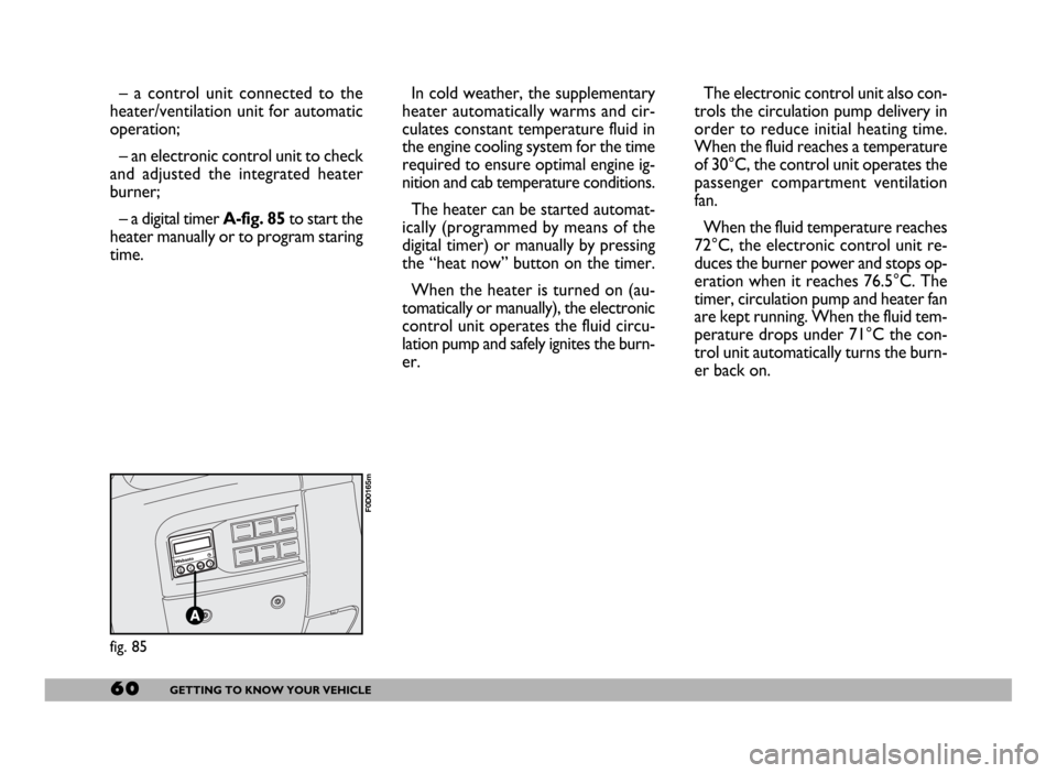
– a digital timer A-fig. 85to start the
heater manually or to program staring
time.In cold weather, the supplementary
heater automatically warms and cir-
culates constant temperature fluid in
the engine cooling system for the time
required to ensure optimal engine ig-
nition and cab temperature conditions.
The heater can be started automat-
ically (programmed by means of the
digital timer) or manually by pressing
the “heat now” button on the timer.
When the heater is turned on (au-
tomatically or manually), the electronic
control unit operates the fluid circu-
lation pump and safely ignites the burn-
er.The electronic control unit also con-
trols the circulation pump delivery in
order to reduce initial heating time.
When the fluid reaches a temperature
of 30°C, the control unit operates the
passenger compartment ventilation
fan.
When the fluid temperature reaches
72°C, the electronic control unit re-
duces the burner power and stops op-
eration when it reaches 76.5°C. The
timer, circulation pump and heater fan
are kept running. When the fluid tem-
perature drops under 71°C the con-
trol unit automatically turns the burn-
er back on.
fig. 85
F0D0165m
Page 74 of 258

73GETTING TO KNOW YOUR VEHICLE
Inspect the vehicle carefully to make
sure there is no fuel leak in the en-
gine compartment, under the vehicle
or near the fuel tank.
If you cannot see any fuel leaks and
the vehicle is in a fit state to continue
its journey, press button A-fig. 105
to reactivate the fuel supply system, as
illustrated.
Remember to turn the ignition key
to STOPto prevent running the bat-
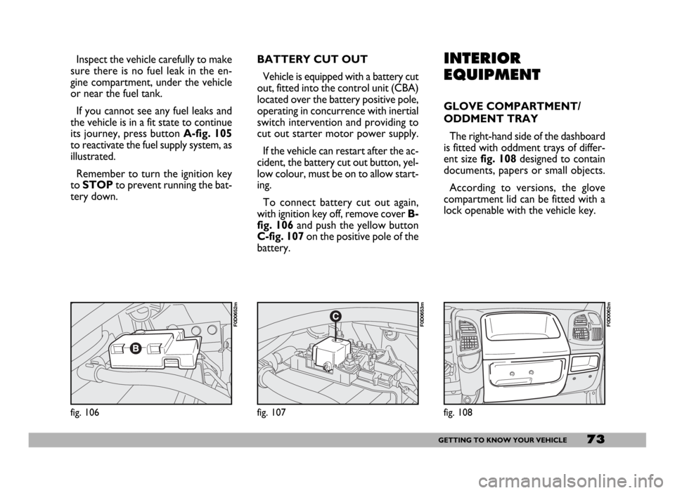
tery down.INTERIOR
EQUIPMENT
GLOVE COMPARTMENT/
ODDMENT TRAY
The right-hand side of the dashboard
is fitted with oddment trays of differ-
ent sizefig. 108designed to contain
documents, papers or small objects.
According to versions, the glove
compartment lid can be fitted with a
lock openable with the vehicle key.
fig. 108
F0D0062m
fig. 106
F0D0652m
fig. 107
F0D0653m
BATTERY CUT OUT
Vehicle is equipped with a battery cut
out, fitted into the control unit (CBA)
located over the battery positive pole,
operating in concurrence with inertial
switch intervention and providing to
cut out starter motor power supply.
If the vehicle can restart after the ac-
cident, the battery cut out button, yel-
low colour, must be on to allow start-
ing.
To connect battery cut out again,
with ignition key off, remove cover B-
fig. 106 and push the yellow button
C-fig. 107 on the positive pole of the
battery.
Page 77 of 258

76GETTING TO KNOW YOUR VEHICLE
IMPORTANTWith the engine off
and the ignition key at MAR, pro-
longed use (e.g.: for more than an
hour) of accessories with high current
intake could deploy the battery, even
preventing the engine from starting. CURRENT SOCKET
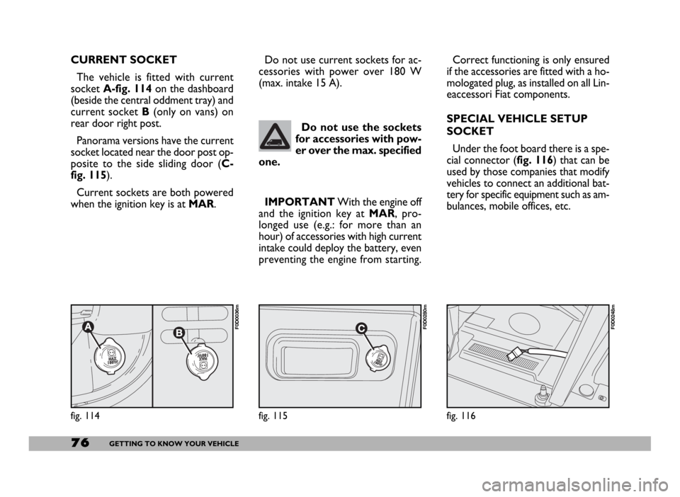
The vehicle is fitted with current
socket A-fig. 114on the dashboard
(beside the central oddment tray) and
current socket B(only on vans) on
rear door right post.
Panorama versions have the current
socket located near the door post op-
posite to the side sliding door (C-
fig. 115).
Current sockets are both powered
when the ignition key is at MAR.
fig. 116
F0D0248m
Do not use the sockets
for accessories with pow-
er over the max. specified
one.
fig. 114
F0D0036m
Correct functioning is only ensured
if the accessories are fitted with a ho-
mologated plug, as installed on all Lin-
eaccessori Fiat components.
SPECIAL VEHICLE SETUP
SOCKET
Under the foot board there is a spe-
cial connector (fig. 116) that can be
used by those companies that modify
vehicles to connect an additional bat-
tery for specific equipment such as am-
bulances, mobile offices, etc. Do not use current sockets for ac-
cessories with power over 180 W
(max. intake 15 A).
fig. 115
F0D0280m