Page 304 of 462
Downloaded from www.Manualslib.com manuals search engine 298
INJECTION
CHECKING THE AIR SUPPLY CIRCUIT
Tool.
[1]Manual pressure-vacuum pump: FACOM DA 16
Checks.
Vacuum pump.
Connect the tool [1]into the vacuum pump (1).
Start the engine.
Wait 30 seconds.
The vacuum value should be 0.9 ± 0.1 barat idle.
NOTE:The exhaust gas recycling valve is not linked to the air supply circuit.
The exhaust gas recycling electrovalve is controlled by the engine ECU.
Turbocharging pressure regulation valve.
Connect the tool [1]on the valve (2)
(tube identified by the colour grey).
Apply a vacuum of approx. 0.8 bar.
Rod "a"should move 12 ± 2 mm.
B1HP1UGC
B1HP1UHC
Engines: 9HY - 9HZ
C4
Angl.-t2-page283-305-2005 9/01/06 10:18 Page 298
Page 305 of 462
![Citroen C4 2005 2.G Workshop Manual Downloaded from www.Manualslib.com manuals search engine 299
INJECTION
CHECKING THE AIR SUPPLY CIRCUIT
B1BP33ZC
B1BP340C
Engine: RHR
B1BP341C
B1BP342C
Tool.
[1]Manual pressure-vacuum pump: FACOM DA 16 Citroen C4 2005 2.G Workshop Manual Downloaded from www.Manualslib.com manuals search engine 299
INJECTION
CHECKING THE AIR SUPPLY CIRCUIT
B1BP33ZC
B1BP340C
Engine: RHR
B1BP341C
B1BP342C
Tool.
[1]Manual pressure-vacuum pump: FACOM DA 16](/manual-img/9/4138/w960_4138-304.png)
Downloaded from www.Manualslib.com manuals search engine 299
INJECTION
CHECKING THE AIR SUPPLY CIRCUIT
B1BP33ZC
B1BP340C
Engine: RHR
B1BP341C
B1BP342C
Tool.
[1]Manual pressure-vacuum pump: FACOM DA 16
IMPERATIVE: Respect the safety and cleanliness specific to high pressure diesel
injection engines.
WARNING: After switching off the ignition, wait 15 minutes before disconnecting
the battery
(to guarantee memorisation of the initialisations of the different ECUS).
Checking the vacuum source
(vacuum pump).
Connect the tool [1] on the take-off «a».
Start the engine.
The value should be: 1 ± 0,2.
Turbocharging pressure electrovalve.
Connect the tool [1]on the vacuum supply «b»of the electrovalve (1).
Start the engine.
The value should be: 1 ± 0,2.
Cold air circuit electrovalve.
Connect the tool [1]on the vacuum supply «c»of the electrovalve (2).
Start the engine.
The value should be: 1 ± 0,2.
Warm air circuit electrovalve.
Connect the tool [1]on the vacuum supply «d»of the electrovalve (3).
Start the engine.
The value should be: 1 ± 0,2.
C4
Angl.-t2-page283-305-2005 9/01/06 10:18 Page 299
Page 307 of 462
Downloaded from www.Manualslib.com manuals search engine 301
INJECTION
CHECKING THE AIR SUPPLY CIRCUIT
Tool.
[1]Manual vacuum pump: FACOM DA 16
IMPERATIVE: Respect the safety and cleanliness requirements.
Vacuum pump.
Connect the tool [1]on the vacuum pump (1).
Start the engine.
Pressure should be 0.8 barat 780 rpm.
Boost pressure regulator electrovalve.
Connect the tool [1]between the electrovalve (2)and the valve (3)of the boost pressure regulator.
Compare readings with the values in the table below.
Engine speed (rpm) Pressure (bar)
780 0,6
4000 0,25
Pressure regulator valve.
Connect the tool [1]on the valve (3).
Appy a pressure of 0.5 barto activate the rod "a".
Rod "a"should move 12 mm.
B1HP12FD
Engines: RHY - RHZ
XSARA PICASSO
Angl.-t2-page283-305-2005 9/01/06 10:18 Page 301
Page 324 of 462

Downloaded from www.Manualslib.com manuals search engine 318
CLUTCH
GEARBOX
TRANSMISSION
HYDRAULIC CLUTCH CONTROL: CHECKS AND ADJUSTMENTS
Bleeding the hydraulic clutch control
Action the clutch pedal manually through its full travel: 7 timesrapidly down and up.
Allow the clutch pedal to come back up to its high position.
Fill the brake fluid reservoir to the maximum of its capacity.
Open the bleed screw at «c».
Action the clutch pedal manually through its entire travel: 7 times
rapidly down and up.
The last time, keep the clutch pedal fully down.
Reclose the bleed screw, at «c».
If necessary, repeat the operation.
Top up the brake fluid to the MAX.level of the brake fluid reservoir.
Work the clutch vigorously 40 times
.
Start the engine.
Apply the handbrake.
Engage a gear.
Check that the clutch starts to engage at a dimension (X)greater than or equal to 45 mm
(the dimension (X)is
given as a guide).
Repeat the bleed operations if necessary.
C5FP0FQC
XSARA PICASSO
B2BP04YC
Angl.-t2-page306-360-2005 9/01/06 10:20 Page 318
Page 358 of 462

Downloaded from www.Manualslib.com manuals search engine 352
CLUTCH
GEARBOX
TRANSMISSION
AL4 GEARBOX CONTROLS
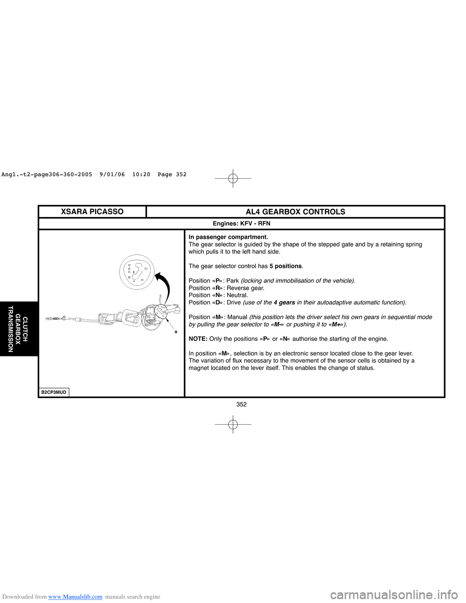
In passenger compartment.
The gear selector is guided by the shape of the stepped gate and by a retaining spring
which pulls it to the left hand side.
The gear selector control has 5 positions.
Position «P»: Park
(locking and immobilisation of the vehicle).
Position «R»: Reverse gear.
Position «N»: Neutral.
Position «D»: Drive
(use of the 4 gearsin their autoadaptive automatic function).
Position «M»: Manual (this position lets the driver select his own gears in sequential mode
by pulling the gear selector to «M-»or pushing it to «M+»).
NOTE:Only the positions «P»or «N»authorise the starting of the engine.
In position «M», selection is by an electronic sensor located close to the gear lever.
The variation of flux necessary to the movement of the sensor cells is obtained by a
magnet located on the lever itself. This enables the change of status.
Engines: KFV - RFN
XSARA PICASSO
B2CP3MUD
Angl.-t2-page306-360-2005 9/01/06 10:20 Page 352
Page 360 of 462

Downloaded from www.Manualslib.com manuals search engine 354
CLUTCH
GEARBOX
TRANSMISSION
AL4 GEARBOX CONTROLS
In passenger compartment.
The selector control has 6 positions.
The gear selector is guided by the shape of the stepped gate and by a retaining spring
which pulls it to the left hand side.
Push the lever to the right to exit from position «P».
NOTE: The vehicle is equipped with the «shift lock»: you have to switch on the ignition
and press the brake pedal to unlock the selector lever from position «P».
P:Park
(system locked).
R:Reverse gear.
N:Neutral.
D:Automatic
(1st to 4th gear).
3:Automatic (1st to 3rd gear).
2:Automatic (1st to 2nd gear).
A switch located to the left of the gear control allows the driver to choose from these
programmes:
- Normal: Conventional use of the automatic gearbox.
- Sport:This programme favours performance.
- Snow:In position «D», starting is in 2ndgear for diesel and in 3rdgear for petrol.
NOTE:Only the positions «P»or «N»authorise the starting of the engine.
Engines: NFU - RFN - RHZ
XSARA
B2CP3ADC
Angl.-t2-page306-360-2005 9/01/06 10:20 Page 354
Page 378 of 462

Downloaded from www.Manualslib.com manuals search engine 372
AXLES
SUSPENSION
STEERING
CHECKING THE POWER STEERING ASSISTANCE PRESSURE
Preliminary operation.
Move aside the high pressure pipe (1).
Do up:
- The union [6]on the power steering electropump.
- The union [7]on the high pressure pipe (1).
- Tighten all the unions.
Fill the power steering reservoir 10 mmabove the max. level.
IMPERATIVE: Use new power steering fluid for both filling and topping-up the circuit.
Open the tap [5].
Start the engine and allow it to run for 5 seconds.
Stop the engine.
Move the steering several timesin each direction.
Check the steering fluid level and make sure that there are no leaks.
Checking the electropump pressure.
Start the engine.
Close the tap [5]for 5 seconds.
Open the tap [5].
Stop the engine.
At accelerated idle
(1200 to 1500rpm), the pressure should be 105 ± 5 bars.
If the electropump pressure is correct, check the valve sealing.
B3EP16EC
C4
Angl.-t2-page361-397-2005 9/01/06 10:22 Page 372
Page 416 of 462

Downloaded from www.Manualslib.com manuals search engine 410
BRAKESBLEEDING AND FILLING THE BRAKING SYSTEM
Bleeding the braking circuit without the bleed apparatus.
NOTE:Two operators are necessary.
For each brake circuit:
- Apply the brake pedal to place the circuit under pressure.
- Couple a transparent tube on the bleed screw.
- Submerge the other end of the tube in a clean container.
- Open the bleed screw.
- Wait until the fluid flows out without air bubbles.
- Close the bleed screw.
NOTE:Recommence the process a second timeif that is necessary.
Check the level of the brake fluid
(between the «DANGER»level and
the «MAXI»level).
Fill if necessary with the the approved and recommended synthetic
brake fluid.Bleeding the secondary braking circuit.
WARNING: During the bleed operations: take care to maintain the
level of the brake fluid in the reservoir, keep it topped up.
NOTE:The bleed apparatus [1]is still connected on the brake fluid
reservoir (4).
Use the diagnostic tools [2]or [3].
Select the menu corresponding to the vehicle:
- ABSmenu
(according to equipment).- ESPmenu (according to equipment).
Follow the instructions of the diagnostic tool.
At the end of the bleed programme, check the level of the brake fluid,
top up if necessary.
Check the travel of the brake pedal: it must not be excessive. If it is,
restart the bleed procedure.
C4
Angl.-t2-PAGE398-427-2005 9/01/06 10:24 Page 410