Page 263 of 462
Downloaded from www.Manualslib.com manuals search engine 257
ENGINE
CHECKING AND SETTING THE VALVE TIMING
Engines: 9HZ - 9HY
B1EP1E8C
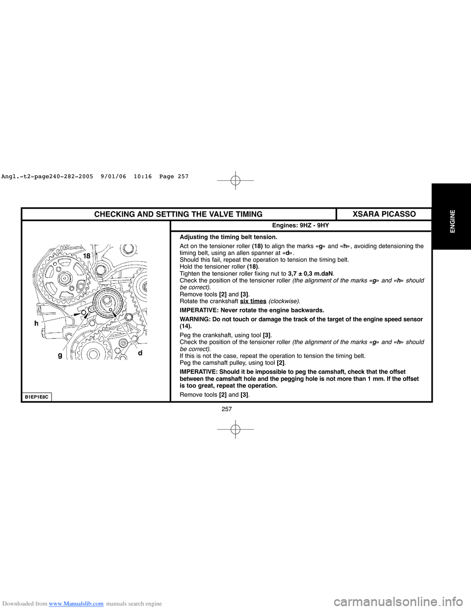
Adjusting the timing belt tension.
Act on the tensioner roller (18)to align the marks «g»and «h», avoiding detensioning the
timing belt, using an allen spanner at «d».
Should this fail, repeat the operation to tension the timing belt.
Hold the tensioner roller (18).
Tighten the tensioner roller fixing nut to 3,7 ± 0,3 m.daN.
Check the position of the tensioner roller
(the alignment of the marks «g»and «h»should
be correct).
Remove tools [2] and [3].
Rotate the crankshaft six times
(clockwise).
IMPERATIVE: Never rotate the engine backwards.
WARNING: Do not touch or damage the track of the target of the engine speed sensor
(14).
Peg the crankshaft, using tool[3].
Check the position of the tensioner roller
(the alignment of the marks «g» and «h»should
be correct).
If this is not the case, repeat the operation to tension the timing belt.
Peg the camshaft pulley, using tool [2].
IMPERATIVE: Should it be impossible to peg the camshaft, check that the offset
between the camshaft hole and the pegging hole is not more than 1 mm. If the offset
is too great, repeat the operation.
Remove tools [2] and [3].
XSARA PICASSO
Angl.-t2-page240-282-2005 9/01/06 10:16 Page 257
Page 296 of 462
![Citroen C4 2005 2.G Workshop Manual Downloaded from www.Manualslib.com manuals search engine 290
INJECTION
CHECKS: TURBO PRESSURE
Tools.
[1]Pressure gauge for checking boost pressure: 4073-T.A
[2] Sleeve for checking boost pressure: (-)](/manual-img/9/4138/w960_4138-295.png "Citroen C4 2005 2.G Workshop Manual Downloaded from www.Manualslib.com manuals search engine 290
INJECTION
CHECKS: TURBO PRESSURE
Tools.
[1]Pressure gauge for checking boost pressure: 4073-T.A
[2] Sleeve for checking boost pressure: (-)")
Downloaded from www.Manualslib.com manuals search engine 290
INJECTION
CHECKS: TURBO PRESSURE
Tools.
[1]Pressure gauge for checking boost pressure: 4073-T.A
[2] Sleeve for checking boost pressure: (-).0171.F
Checks.
IMPERATIVE: Respect the following test conditions:
- Engine at operating temperature.
- Vehicle in running order.
- Engine under full load.
Preparation.
Remove the clips (1).
Fit the tool [2]in the place of the duct (2).
Couple the sleeve [2] on the pressure gauge[1]using the tube «a».
Mode of operation.
Position tool [1]in the vehicle.
Start the engine.
Engagefirst gear, start the vehicle.
Engage the gears up to third gear.
Decelerate to an engine speed of 1000 rpm.
Check the pressure: 0,6 ± 0,05bar
(1500 rpm).
Accelerate freely (change from fourth gear to third gear).Check the pressure: 0,9 ± 0,05bar (between 2500and 3500rpm).
Remove tools [1], [2] and «a».
Reposition the tube (2)and tighten the clips(1).
B1BP2NXD
C5FP06RC
Engines: 8HX - 8HZ
XSARA
Angl.-t2-page283-305-2005 9/01/06 10:18 Page 290
Page 297 of 462
Downloaded from www.Manualslib.com manuals search engine INJECTION
291
CHECKS: TURBO PRESSURE
IMPERATIVE: Respect the safety and cleanliness requirements.
Preparation.
IMPERATIVE: Respect the following test conditions:
- Engine at operating temperature.
- Vehicle in running order.
- Engine under full load.
Connect the diagnostic tool to the vehicle's diagnostic socket, carry out parameter measures.
Mode of operation.
Start the engine.
Engage first gear, start the vehicle.
Engage the gears up to third gear.
Decelerate to an engine speed of 1000 rpm.
Check the pressure: 0,6 ± 0,05 bar
(1500 rpm).
Accelerate freely (change from fourth gear to third gear).Check the pressure: 0,9 ± 0,05 bar (between 2500and 3500rpm).
Engines: 9HX - 9HY - 9HZ
C4
Angl.-t2-page283-305-2005 9/01/06 10:18 Page 291
Page 298 of 462
Downloaded from www.Manualslib.com manuals search engine 292
INJECTION
CHECKS: TURBO PRESSURE
IMPERATIVE: Respect the safety and cleanliness requirements.
Preparation.
IMPERATIVE: Respect the following test conditions:
- Engine at operating temperature.
- Vehicle in running order.
- Engine under full load.
Connect the diagnostic tool to the vehicle's diagnostic socket, carry out parameter measures.
Mode of operation.
Start the engine.
Engage first gear, start the vehicle.
Engage the gears up to third gear.
Decelerate to an engine speed of 1000 rpm.
Check the pressure: 0,6 ± 0,05 bar
(1500 rpm).
Accelerate freely (change from fourth gear to third gear).Check the pressure: 0,9 ± 0,05 bar (between 2500and 3500rpm).
Engines: 9HZ - 9HY
XSARA PICASSO
Angl.-t2-page283-305-2005 9/01/06 10:18 Page 292
Page 307 of 462
Downloaded from www.Manualslib.com manuals search engine 301
INJECTION
CHECKING THE AIR SUPPLY CIRCUIT
Tool.
[1]Manual vacuum pump: FACOM DA 16
IMPERATIVE: Respect the safety and cleanliness requirements.
Vacuum pump.
Connect the tool [1]on the vacuum pump (1).
Start the engine.
Pressure should be 0.8 barat 780 rpm.
Boost pressure regulator electrovalve.
Connect the tool [1]between the electrovalve (2)and the valve (3)of the boost pressure regulator.
Compare readings with the values in the table below.
Engine speed (rpm) Pressure (bar)
780 0,6
4000 0,25
Pressure regulator valve.
Connect the tool [1]on the valve (3).
Appy a pressure of 0.5 barto activate the rod "a".
Rod "a"should move 12 mm.
B1HP12FD
Engines: RHY - RHZ
XSARA PICASSO
Angl.-t2-page283-305-2005 9/01/06 10:18 Page 301
Page 308 of 462
Downloaded from www.Manualslib.com manuals search engine 302
INJECTION
CHECKS: EXHAUST GASES RECYCLING CIRCUIT
Tool.
[1] Manual pressure-vacuum pump: FACOM DA 16
IMPERATIVE: Respect the safety and cleanliness requirements.
EGR valve.
Connect tool [1] on the capsule take-off (2).
Apply a vacuum of approx. 0,6 barseveral times to activate the rod «a».
In abruptly suppressing the vacuum, the valve should click and lock itself back on its seating.
Regulation electrovalve (EGR).
Check to be performed between the electrovalve (1)and the EGR valve (2).
Link the tool [1]in series, between the electrovalve (1)and the capsule (2).
Compare the values noted with those in the table below.
Engine speed (rpm) Vacuum value
780 0,5 bar
2500 0 bar
B1HP1K6D
Engines: 8HX - 8HZ
XSARA
Angl.-t2-page283-305-2005 9/01/06 10:18 Page 302
Page 310 of 462
Downloaded from www.Manualslib.com manuals search engine 304
INJECTION
CHECKS: EXHAUST GASES RECYCLING CIRCUIT
Tool.
[1]Manual vacuum pump: FACOM DA 16
IMPERATIVE: Respect the safety and cleanliness requirements.
EGR valve.
Connect the tool [1]to the capsule union (1).
Apply, several times in succession, a vacuum of approx. 0.6 barto activate the rod "a".
In abrupt reaction to the vacuum, the valve should close on its seating with a clicking noise.
Exhaust gas reycling (EGR) electrovalve.
Check, not under load, between the electrovalve (2)and the EGR valve (1).
Connect the tool [1]between the electrovalve (2)and the capsule (1).
Compare readings with the values in the table below.
Engine speed (rpm) Vacuum value
780 0,5 bar
2500 0 bar
B1HP12GD
Engines: RHY - RHZ
XSARA PICASSO
Angl.-t2-page283-305-2005 9/01/06 10:18 Page 304
Page 312 of 462

Downloaded from www.Manualslib.com manuals search engine 306
CLUTCH
GEARBOX
TRANSMISSION
SPEEDOMETER
An E.E.C. decree of 25 June 1976, regulates the speed displayed by the speedmeter in relation to the actual speed travelled.
This decree stipulates:
- The speed indicated by a speedometer must never be lower than the actual vehicle speed.
- Between the speed displayed «SD»and the speed travelled «ST», there must always be the following relationship:
ST < SD < 1.10 ST + 4 Kph
Example:For an actual speed of 100 Kphthe speed displayed by the speedometer may be between 100and 114 Kph.
The speed indicated by the speedometer may be influenced by:
- The speedometer.
- The tyres fitted to the vehicle.
- The final drive ratio.
- The speedometer drive ratio.
Any of these components can be checked without removing them from the vehicle
(see information note N° 78-85 TT of 19 October 1978).
NOTE:Before replacing the speedometer, check the conformity of the following points:
- The tyres fitted to the vehicle.
- The gearbox final drive ratio.
- The speedometer drive ratio.
Angl.-t2-page306-360-2005 9/01/06 10:20 Page 306


![Citroen C4 2005 2.G Workshop Manual Downloaded from www.Manualslib.com manuals search engine 301
INJECTION
CHECKING THE AIR SUPPLY CIRCUIT
Tool.
[1]Manual vacuum pump: FACOM DA 16
IMPERATIVE: Respect the safety and cleanliness requireme](/manual-img/9/4138/w960_4138-306.png "Citroen C4 2005 2.G Workshop Manual Downloaded from www.Manualslib.com manuals search engine 301
INJECTION
CHECKING THE AIR SUPPLY CIRCUIT
Tool.
[1]Manual vacuum pump: FACOM DA 16
IMPERATIVE: Respect the safety and cleanliness requireme")
![Citroen C4 2005 2.G Workshop Manual Downloaded from www.Manualslib.com manuals search engine 302
INJECTION
CHECKS: EXHAUST GASES RECYCLING CIRCUIT
Tool.
[1] Manual pressure-vacuum pump: FACOM DA 16
IMPERATIVE: Respect the safety and cle](/manual-img/9/4138/w960_4138-307.png "Citroen C4 2005 2.G Workshop Manual Downloaded from www.Manualslib.com manuals search engine 302
INJECTION
CHECKS: EXHAUST GASES RECYCLING CIRCUIT
Tool.
[1] Manual pressure-vacuum pump: FACOM DA 16
IMPERATIVE: Respect the safety and cle")
![Citroen C4 2005 2.G Workshop Manual Downloaded from www.Manualslib.com manuals search engine 304
INJECTION
CHECKS: EXHAUST GASES RECYCLING CIRCUIT
Tool.
[1]Manual vacuum pump: FACOM DA 16
IMPERATIVE: Respect the safety and cleanliness r](/manual-img/9/4138/w960_4138-309.png "Citroen C4 2005 2.G Workshop Manual Downloaded from www.Manualslib.com manuals search engine 304
INJECTION
CHECKS: EXHAUST GASES RECYCLING CIRCUIT
Tool.
[1]Manual vacuum pump: FACOM DA 16
IMPERATIVE: Respect the safety and cleanliness r")