Page 5 of 462

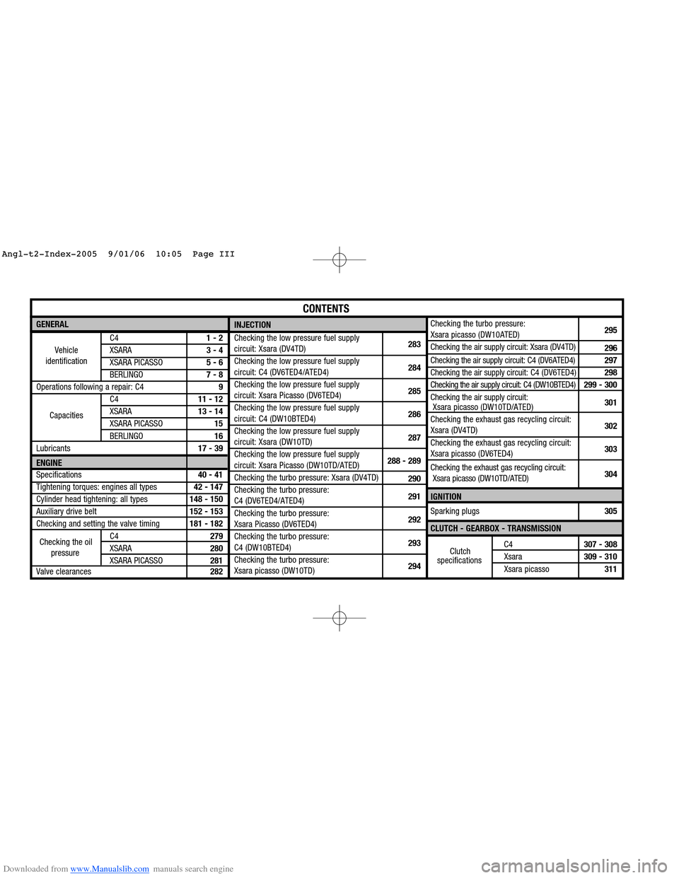
Downloaded from www.Manualslib.com manuals search engine GENERAL
C41 - 2
XSARA3 - 4
XSARA PICASSO5 - 6
BERLINGO7 - 8
Operations following a repair: C49
C411 - 12
XSARA13 - 14
XSARA PICASSO15
BERLINGO16
Lubricants17 - 39
ENGINE
Specifications40 - 41
Tightening torques: engines all types42 - 147
Cylinder head tightening: all types148 - 150
Auxiliary drive belt152 - 153
Checking and setting the valve timing181 - 182
C4279
XSARA280
XSARA PICASSO281
Valve clearances282Checking the turbo pressure:
Xsara picasso (DW10ATED)295
Checking the air supply circuit: Xsara (DV4TD)
296
Checking the air supply circuit: C4 (DV6ATED4)297
Checking the air supply circuit: C4 (DV6TED4)298
Checking the air supply circuit: C4 (DW10BTED4)299 - 300
Checking the air supply circuit:
Xsara picasso (DW10TD/ATED)301
Checking the exhaust gas recycling circuit:
Xsara (DV4TD)302
Checking the exhaust gas recycling circuit:
Xsara picasso (DV6TED4)303
Checking the exhaust gas recycling circuit:
Xsara picasso (DW10TD/ATED)304
IGNITION
Sparking plugs305
CLUTCH - GEARBOX - TRANSMISSION
C4307 - 308
Xsara309 - 310
Xsara picasso311
CONTENTS
Vehicle
identification
Capacities
INJECTION
Checking the low pressure fuel supply
circuit: Xsara (DV4TD)283
Checking the low pressure fuel supply
circuit: C4 (DV6TED4/ATED4)284
Checking the low pressure fuel supply
circuit: Xsara Picasso (DV6TED4)285
Checking the low pressure fuel supply
circuit: C4 (DW10BTED4)286
Checking the low pressure fuel supply
circuit: Xsara (DW10TD)287
Checking the low pressure fuel supply
circuit: Xsara Picasso (DW10TD/ATED)288 - 289
Checking the turbo pressure: Xsara (DV4TD)
290
Checking the turbo pressure:
C4 (DV6TED4/ATED4)291
Checking the turbo pressure:
Xsara Picasso (DV6TED4)292
Checking the turbo pressure:
C4 (DW10BTED4)293
Checking the turbo pressure:
Xsara picasso (DW10TD)294
Checking the oil
pressureClutch
specifications
Angl-t2-Index-2005 9/01/06 10:05 Page III
Page 250 of 462
Downloaded from www.Manualslib.com manuals search engine 244
ENGINECHECKING AND SETTING THE VALVE TIMING
Engines: 9HX - 9HY - 9HZ
Checking and setting the timing (continued).
Turn the engine in the normal direction of rotation until the peg [1]engages in the setting hole.
Peg the flywheel at «b», using tool [1].
Move aside the electrical harness (6).
Remove:
- The engine support (7).
- The screw (8).
- The accessories drive pulley (9).
- The lower timing cover (10).
- The upper timing cover (11).
- The tool [1].
Refit the screw (8).
Rotate the crankshaft to bring the camshaft to its pegging point.
Peg:
- The camshaft at «c», using tool [2]
(oil the pegs).
- The fuel high pressure pump pulley (15)at «f»using a 5 mmdiameter peg.
WARNING: Do not touch or damage the track of the engine speed sensor target (14).
B1BP305C
B1EP1HJD
C4
Angl.-t2-page240-282-2005 9/01/06 10:16 Page 244
Page 353 of 462
Downloaded from www.Manualslib.com manuals search engine 347
CLUTCH
GEARBOX
TRANSMISSION
TIGHTENING TORQUES: AL4 AUTOMATIC GEARBOX
Engines: NFU - RFJ
B2CP3EDD
B2CP3X7D
Tightening torques (m.daN).
(1) Fixing of the electrovalve for modulation of the flow
of oil into the exchanger (EPDE): 1 ± 0,2
(2)Heat exchanger fixing: 5 ± 1
(3) Output speed sensor fixing
(4)Output speed sensor fixing: 1 ± 0,2
(5)Oil overflow and drain fixing(X = 48 mm)
: 0,9 ± 0,2
(6)Oil level plug: 3,3 ± 0,5
(7)Oil pressure sensor fixing: 0,8 ± 0,1
C4 - XSARA - XSARA PICASSO
Angl.-t2-page306-360-2005 9/01/06 10:20 Page 347
Page 435 of 462

Downloaded from www.Manualslib.com manuals search engine 429
AIR
CONDITIONING
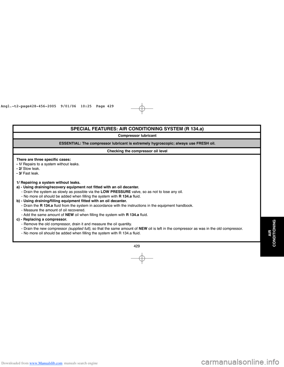
ESSENTIAL: The compressor lubricant is extremely hygroscopic; always use FRESH oil.
Checking the compressor oil level
There are three specific cases:
- 1/Repairs to a system without leaks.
- 2/Slow leak.
- 3/Fast leak.
1/ Repairing a system without leaks.
a) - Using draining/recovery equipment not fitted with an oil decanter.
- Drain the system as slowly as possible via the LOW PRESSUREvalve, so as not to lose any oil.
- No more oil should be added when filling the system with R 134.afluid.
b) - Using draining/filling equipment fitted with an oil decanter.
- Drain the R 134.afluid from the system in accordance with the instructions in the equipment handbook.
- Measure the amount of oil recovered.
- Add the same amount of NEWoil when filling the system with R 134.afluid.
c) - Replacing a compressor.
- Remove the old compressor, drain it and measure the oil quantity.
- Drain the new compressor
(supplied full), so that the same amount of NEWoil is left in the compressor as was in the old compressor.
- No more oil should be added when filling the system with R 134.a fluid.
SPECIAL FEATURES: AIR CONDITIONING SYSTEM (R 134.a)
Compressor lubricant
Angl.-t2-page428-456-2005 9/01/06 10:25 Page 429
Page 436 of 462
Downloaded from www.Manualslib.com manuals search engine 430
AIR
CONDITIONING
Checking the compressor oil level (continued)
2/ Slow leak.
Slow leaks do not lead to oil loss, therefore the same procedure should be followed as if there was no leak at all.
3/ Fast leak.
This type of leak causes both oil loss as well as allowing air to enter the system.
It is therefore necessary to:
- Replace the dehydrator.
- Drain as much oil as possible
(when replacing the faulty component).
Either before or during filling of the system with R 134.afluid, introduce 80 ccof NEWoil into the circuit.
When changing one of the following components, add the quantity stated:
- A drying bottle : 15 ccof compressor oil.
- A condenser or an evaporator : 20 ccof compressor oil.
- High pressure or low pressure pipework : 5 ccof compressor oil.
- A drying cartridge : 15 ccof compressor oil.
SPECIAL FEATURES: AIR CONDITIONING SYSTEM (R 134.a)
Angl.-t2-page428-456-2005 9/01/06 10:25 Page 430