Page 346 of 462
![Citroen BERLINGO 2005 1.G Workshop Manual Downloaded from www.Manualslib.com manuals search engine 340
CLUTCH
GEARBOX
TRANSMISSION
CHECKS AND ADJUSTMENTS: BE4/5 GEARBOX CONTROLS
Tools.
[1]Tool for positioning the gear lever: 9607-T
Adjustment Citroen BERLINGO 2005 1.G Workshop Manual Downloaded from www.Manualslib.com manuals search engine 340
CLUTCH
GEARBOX
TRANSMISSION
CHECKS AND ADJUSTMENTS: BE4/5 GEARBOX CONTROLS
Tools.
[1]Tool for positioning the gear lever: 9607-T
Adjustment](/manual-img/9/4138/w960_4138-345.png)
Downloaded from www.Manualslib.com manuals search engine 340
CLUTCH
GEARBOX
TRANSMISSION
CHECKS AND ADJUSTMENTS: BE4/5 GEARBOX CONTROLS
Tools.
[1]Tool for positioning the gear lever: 9607-T
Adjustments.
WARNING: Cables should be adjusted each time
the gearbox, gear controls or power unit are
removed.
Inside the vehicle.
Remove the trim under the gear lever.
Lock the gear lever in neutral position, using tool [1].
Under the bonnet.
Remove the air filter assembly.
Unlock the ball-joint keys at «a».
Place the gear selection and control levers on neutral.
Lock the cable lengths with the ball-joint locking keys.Checks.
Remove the tool [1].
Check that all the gears engage without «tightness».
Check that the gear lever moves identically forwards
and backwards and to right and left.
If it does not, repeat the adjustment.
Refit the trim under the gear lever.
Refit the air filter assembly.
Adjusting the gear controls Engines: NFV - 6FZ - RFN - WJY - 8HX - 8HZ - 9HZ - 9HY - RHY - RHZ
XSARA - XSARA PICASSO
B2CP3C6CB2CP3C0C
Angl.-t2-page306-360-2005 9/01/06 10:20 Page 340
Page 350 of 462
Downloaded from www.Manualslib.com manuals search engine 344
CLUTCH
GEARBOX
TRANSMISSION
RECOMMENDATIONS/PRECAUTIONS : AL4 AUTOMATIC GEARBOX
Precautions to be taken
Repairs on mechanical components.
Never place the gearbox on the ground without protection.
In order to avoid breaking the input shaft ring, it is imperative
that the
converter retaining bracket should be in place when handling the
gearbox.
It is imperative
to use the centring peg and the converter retaining
bracket to couple the gearbox on the engine.
After coupling the gearbox on the engine, remove the centring peg. Modification of the oil usage counter value.
Exchanging the gearbox ECU:
- Note down the gearbox counter value.
- Transfer the value read into the the new gearbox ECU.
Exchanging the gearbox:
- Initialise the oil usage counter to 0.
Draining the gearbox:
- Initialise the oil usage counter
(follow the diagnostic tool procedure).
Angl.-t2-page306-360-2005 9/01/06 10:20 Page 344
Page 351 of 462

Downloaded from www.Manualslib.com manuals search engine 345
CLUTCH
GEARBOX
TRANSMISSION
RECOMMENDATIONS/PRECAUTIONS : AL4 AUTOMATIC GEARBOX
Procedure to be followed prior to carrying out repairs on AL4 autoactive gearbox
If a gearbox malfunction occurs, there are two possible configurations
depending on the seriousness of the fault:
- Gearbox in back-up mode with a replacement programme of
(the fault
values are taken in substitution).
- Gearbox in back-up mode with an emergency programme (3rd hydraulic).
WARNING: In the emergency programme, an impact is felt when
changing P/R, N/R and N/D.
Réception client.
Discuss with the customer, to find out all the malfunction symptoms.
Oil quality - Oil level.
Oil quality.
If the gearbox has suffered a serious fault resulting in a malfunction or
the destruction of a clutch, the oil will overheat and become
contaminated with impurities: the oil is said to be «burnt».
This is characterised by a black colour and the presence of an
unpleasant smell.
ESSENTIAL: The gearbox must be replaced.Oil level
(see corresponding operation).
An excessive oil level can result in the following consequences:
- Excessive heating of the oil.
- Oil leaks.
An insufficent level causes the destruction of the gearbox.
Top up the level of oil in the gearbox
(if necessary).
Check using a diagnostic tool.
Read the fault codes
(engine and gearbox).
Absence of fault codes.
Carry out parameter measures, actuator tests and a road test.
Presence of fault codes.
Carry out the necessary repairs.
Delete the fault codes.
Carry out a road test to check the repair and, if need be, modify the
gearbox ECU parameters
(this is essential after an initialisation of the
ECU).
Angl.-t2-page306-360-2005 9/01/06 10:20 Page 345
Page 415 of 462
Downloaded from www.Manualslib.com manuals search engine 409
BRAKES
BLEEDING AND FILLING THE BRAKING SYSTEM
Bleeding the braking circuit with the bleed apparatus.
Connect the bleed apparatus [1]on the brake fluid reservoir (4).
Adjust the apparatus pressure to 2 bars.
For each brake circuit:
- Couple a transparent tube on the bleed screw.
- Submerge the other end of the tube in a clean container.
- Open the bleed screw.
- Wait until the brake fluid flows out without air bubbles.
- Close the bleed screw.
- Remove the bleed apparatus [1].
Check the level of the brake fluid
(between the «DANGER»level and the «MAXI»level).
Fill if necessary with the the approved and recommended synthetic brake fluid.
C4
Angl.-t2-PAGE398-427-2005 9/01/06 10:24 Page 409
Page 416 of 462

Downloaded from www.Manualslib.com manuals search engine 410
BRAKESBLEEDING AND FILLING THE BRAKING SYSTEM
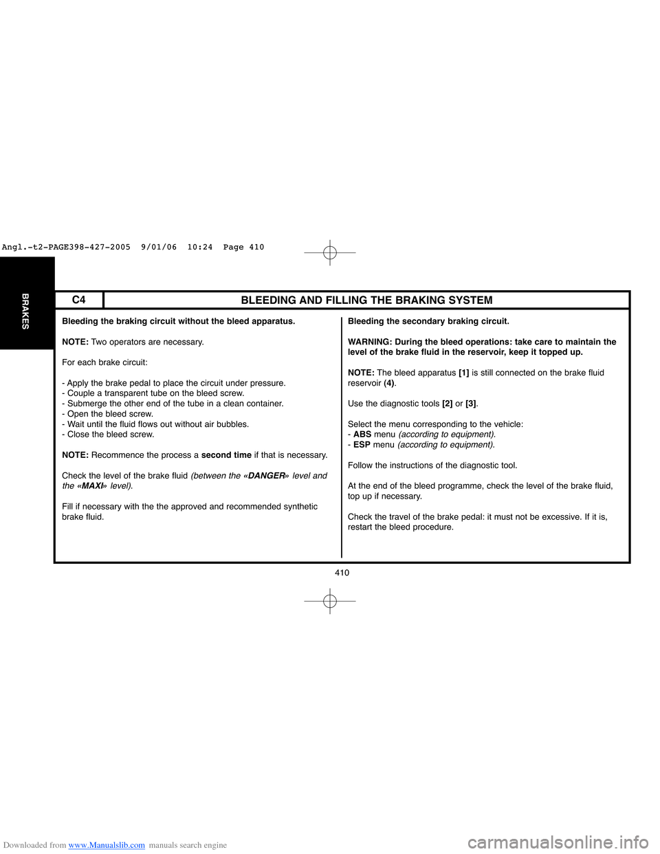
Bleeding the braking circuit without the bleed apparatus.
NOTE:Two operators are necessary.
For each brake circuit:
- Apply the brake pedal to place the circuit under pressure.
- Couple a transparent tube on the bleed screw.
- Submerge the other end of the tube in a clean container.
- Open the bleed screw.
- Wait until the fluid flows out without air bubbles.
- Close the bleed screw.
NOTE:Recommence the process a second timeif that is necessary.
Check the level of the brake fluid
(between the «DANGER»level and
the «MAXI»level).
Fill if necessary with the the approved and recommended synthetic
brake fluid.Bleeding the secondary braking circuit.
WARNING: During the bleed operations: take care to maintain the
level of the brake fluid in the reservoir, keep it topped up.
NOTE:The bleed apparatus [1]is still connected on the brake fluid
reservoir (4).
Use the diagnostic tools [2]or [3].
Select the menu corresponding to the vehicle:
- ABSmenu
(according to equipment).- ESPmenu (according to equipment).
Follow the instructions of the diagnostic tool.
At the end of the bleed programme, check the level of the brake fluid,
top up if necessary.
Check the travel of the brake pedal: it must not be excessive. If it is,
restart the bleed procedure.
C4
Angl.-t2-PAGE398-427-2005 9/01/06 10:24 Page 410
Page 434 of 462
Downloaded from www.Manualslib.com manuals search engine AIR CONDITIONING R 134.a (HFC)
Vehicle
All types
C4(except DW10BTED4)
09/04 ➔ ➔
450 ± 25SD 7C 12
DW10BTED4 SD 6 C 12
XSARAAll types 10/00 ➔ ➔
565 ± 25
135 SP 10
TU5JP + EW7
XSARAEW10J412/02 ➔ ➔
675 ± 50
SD 6 V 12
PICASSODV6TED4 01/04 ➔ ➔
625 ± 50
DW10 12/02 ➔ ➔
675 ± 50 Engines DateRefrigerant
refill (gr)Compressor
Variable
CapacityOil quantity
ccOil reference
428
AIR
CONDITIONING
Angl.-t2-page428-456-2005 9/01/06 10:25 Page 428
Page 435 of 462

Downloaded from www.Manualslib.com manuals search engine 429
AIR
CONDITIONING
ESSENTIAL: The compressor lubricant is extremely hygroscopic; always use FRESH oil.
Checking the compressor oil level
There are three specific cases:
- 1/Repairs to a system without leaks.
- 2/Slow leak.
- 3/Fast leak.
1/ Repairing a system without leaks.
a) - Using draining/recovery equipment not fitted with an oil decanter.
- Drain the system as slowly as possible via the LOW PRESSUREvalve, so as not to lose any oil.
- No more oil should be added when filling the system with R 134.afluid.
b) - Using draining/filling equipment fitted with an oil decanter.
- Drain the R 134.afluid from the system in accordance with the instructions in the equipment handbook.
- Measure the amount of oil recovered.
- Add the same amount of NEWoil when filling the system with R 134.afluid.
c) - Replacing a compressor.
- Remove the old compressor, drain it and measure the oil quantity.
- Drain the new compressor
(supplied full), so that the same amount of NEWoil is left in the compressor as was in the old compressor.
- No more oil should be added when filling the system with R 134.a fluid.
SPECIAL FEATURES: AIR CONDITIONING SYSTEM (R 134.a)
Compressor lubricant
Angl.-t2-page428-456-2005 9/01/06 10:25 Page 429
Page 436 of 462
Downloaded from www.Manualslib.com manuals search engine 430
AIR
CONDITIONING
Checking the compressor oil level (continued)
2/ Slow leak.
Slow leaks do not lead to oil loss, therefore the same procedure should be followed as if there was no leak at all.
3/ Fast leak.
This type of leak causes both oil loss as well as allowing air to enter the system.
It is therefore necessary to:
- Replace the dehydrator.
- Drain as much oil as possible
(when replacing the faulty component).
Either before or during filling of the system with R 134.afluid, introduce 80 ccof NEWoil into the circuit.
When changing one of the following components, add the quantity stated:
- A drying bottle : 15 ccof compressor oil.
- A condenser or an evaporator : 20 ccof compressor oil.
- High pressure or low pressure pipework : 5 ccof compressor oil.
- A drying cartridge : 15 ccof compressor oil.
SPECIAL FEATURES: AIR CONDITIONING SYSTEM (R 134.a)
Angl.-t2-page428-456-2005 9/01/06 10:25 Page 430