2005 CHRYSLER VOYAGER seat memory
[x] Cancel search: seat memoryPage 1800 of 2339
(4) Place front door trim panel in position on door.
(5) Install trim panel into inner belt molding at
top of door.
(6) Install clips to attach door trim to door frame
around perimeter of panel.
(7) If equipped, install screw to attach door trim to
door panel behind inside latch release handle.
(8) If equipped, connect power switch into wire
connector.
(9) Place power accessary switch in position on
door trim.
(10) Connect wire connector into memory seat/mir-
ror switch and install switch into trim panel.
(11) Install screws to attach accessary switch
panel to door trim.
(12) Install screw cover into switch panel.
(13) If equipped, install window crank.
(14) If equipped, install screws to attach trim
panel to door inside map pocket.
(15) If equipped, install screw to attach door pull
cup to inner door panel.
(16) If equipped, install screws to attach door
assist handle to inner door panel.
(17) Connect wire connector into courtesy lamp.
(18) Install lamp in door trim.
(19) Install switch bezel.
WATERSHIELD
REMOVAL
(1) Remove door trim panel. (Refer to 23 - BODY/
DOOR - FRONT/TRIM PANEL - REMOVAL)
(2) Remove the front door speaker. (Refer to 8 -
ELECTRICAL/AUDIO/SPEAKER - REMOVAL)
(3) Peel watershield away from adhesive around
perimeter of inner door panel.
INSTALLATION
(1) Insure that enough adhesive remains to
securely retain the water dam. Replace as necessary.
(2) Place the shield into position and press
securely to adhesive making sure to properly route
wiring and linkages.
(3) Install the front door speaker. (Refer to 8 -
ELECTRICAL/AUDIO/SPEAKER - INSTALLATION)
(4) Install door trim panel. (Refer to 23 - BODY/
DOOR - FRONT/TRIM PANEL - INSTALLATION)
WINDOW CRANK
REMOVAL
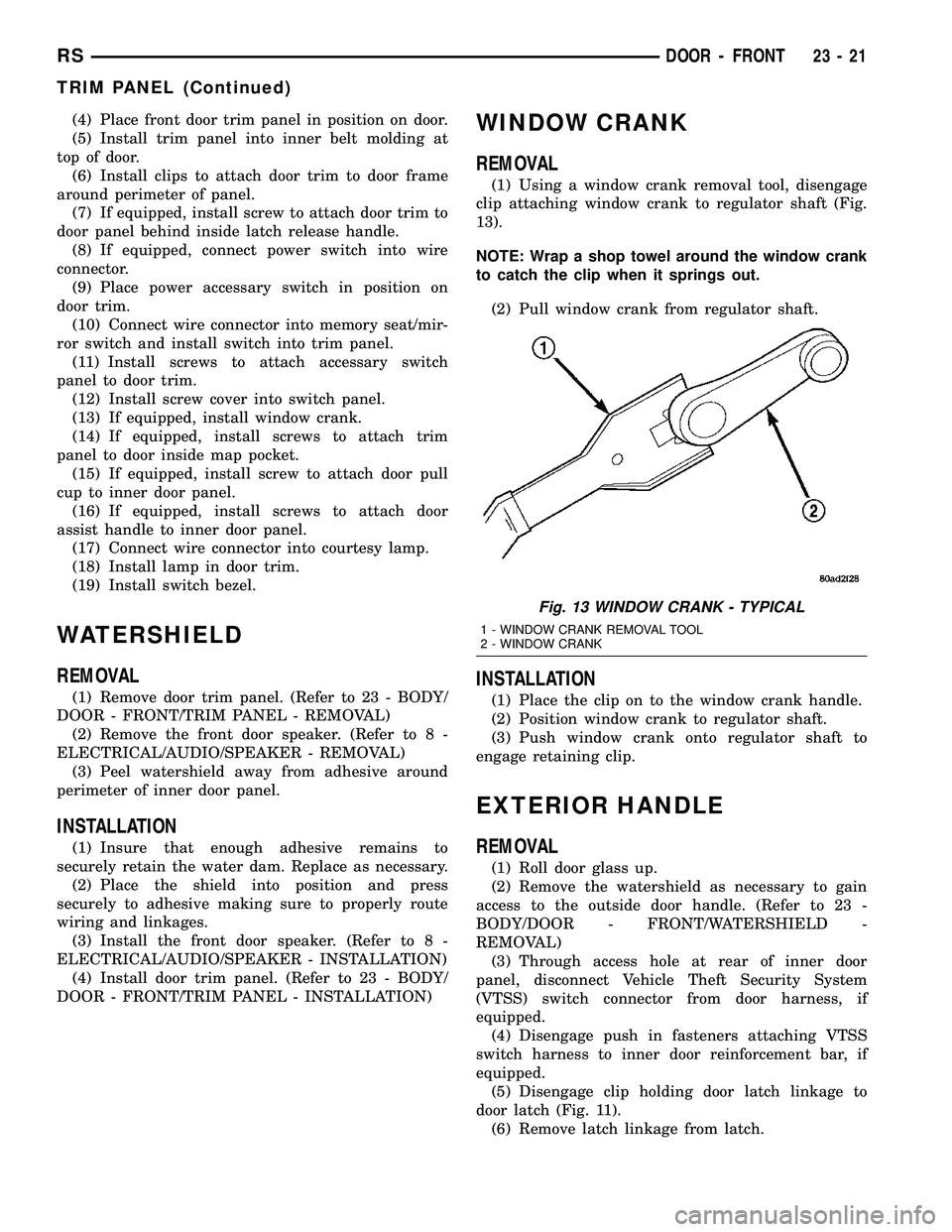
(1) Using a window crank removal tool, disengage
clip attaching window crank to regulator shaft (Fig.
13).
NOTE: Wrap a shop towel around the window crank
to catch the clip when it springs out.
(2) Pull window crank from regulator shaft.
INSTALLATION
(1) Place the clip on to the window crank handle.
(2) Position window crank to regulator shaft.
(3) Push window crank onto regulator shaft to
engage retaining clip.
EXTERIOR HANDLE
REMOVAL
(1) Roll door glass up.
(2) Remove the watershield as necessary to gain
access to the outside door handle. (Refer to 23 -
BODY/DOOR - FRONT/WATERSHIELD -
REMOVAL)
(3) Through access hole at rear of inner door
panel, disconnect Vehicle Theft Security System
(VTSS) switch connector from door harness, if
equipped.
(4) Disengage push in fasteners attaching VTSS
switch harness to inner door reinforcement bar, if
equipped.
(5) Disengage clip holding door latch linkage to
door latch (Fig. 11).
(6) Remove latch linkage from latch.
Fig. 13 WINDOW CRANK - TYPICAL
1 - WINDOW CRANK REMOVAL TOOL
2 - WINDOW CRANK
RSDOOR - FRONT23-21
TRIM PANEL (Continued)
Page 1887 of 2339
RECLINER HANDLE
REMOVAL
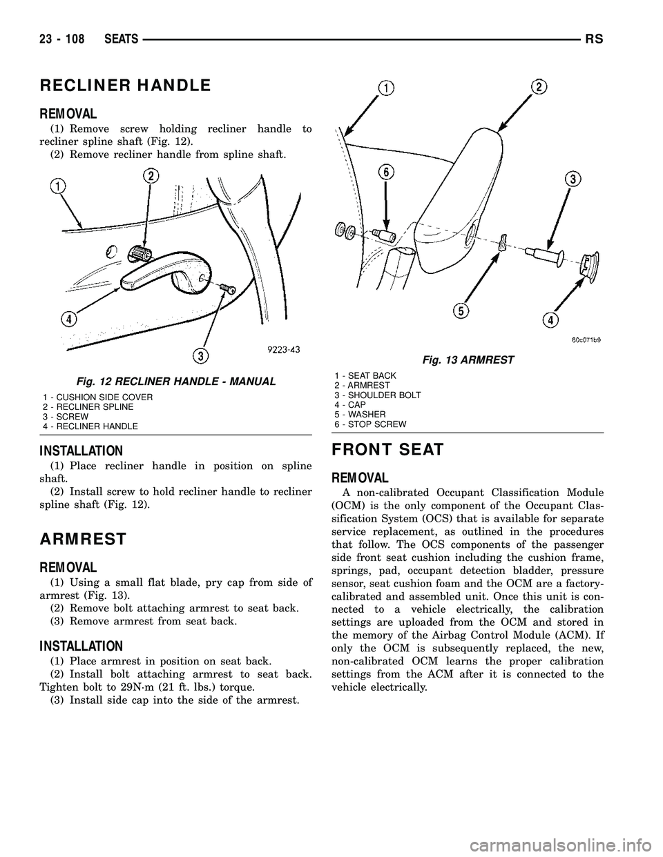
(1) Remove screw holding recliner handle to
recliner spline shaft (Fig. 12).
(2) Remove recliner handle from spline shaft.
INSTALLATION
(1) Place recliner handle in position on spline
shaft.
(2) Install screw to hold recliner handle to recliner
spline shaft (Fig. 12).
ARMREST
REMOVAL
(1) Using a small flat blade, pry cap from side of
armrest (Fig. 13).
(2) Remove bolt attaching armrest to seat back.
(3) Remove armrest from seat back.
INSTALLATION
(1) Place armrest in position on seat back.
(2) Install bolt attaching armrest to seat back.
Tighten bolt to 29N´m (21 ft. lbs.) torque.
(3) Install side cap into the side of the armrest.
FRONT SEAT
REMOVAL
A non-calibrated Occupant Classification Module
(OCM) is the only component of the Occupant Clas-
sification System (OCS) that is available for separate
service replacement, as outlined in the procedures
that follow. The OCS components of the passenger
side front seat cushion including the cushion frame,
springs, pad, occupant detection bladder, pressure
sensor, seat cushion foam and the OCM are a factory-
calibrated and assembled unit. Once this unit is con-
nected to a vehicle electrically, the calibration
settings are uploaded from the OCM and stored in
the memory of the Airbag Control Module (ACM). If
only the OCM is subsequently replaced, the new,
non-calibrated OCM learns the proper calibration
settings from the ACM after it is connected to the
vehicle electrically.
Fig. 12 RECLINER HANDLE - MANUAL
1 - CUSHION SIDE COVER
2 - RECLINER SPLINE
3 - SCREW
4 - RECLINER HANDLE
Fig. 13 ARMREST
1 - SEAT BACK
2 - ARMREST
3 - SHOULDER BOLT
4 - CAP
5 - WASHER
6 - STOP SCREW
23 - 108 SEATSRS
Page 1889 of 2339
INSTALLATION
A non-calibrated Occupant Classification Module
(OCM) is the only component of the Occupant Clas-
sification System (OCS) that is available for separate
service replacement, as outlined in the procedures
that follow. The OCS components of the passenger
side front seat cushion including the cushion frame,
springs, pad, occupant detection bladder, pressure
sensor, seat cushion foam and the OCM are a factory-
calibrated and assembled unit. Once this unit is con-
nected to a vehicle electrically, the calibration
settings are uploaded from the OCM and stored in
the memory of the Airbag Control Module (ACM). If
only the OCM is subsequently replaced, the new,
non-calibrated OCM learns the proper calibration
settings from the ACM after it is connected to the
vehicle electrically.
If any of the remaining OCS components of the
passenger side front seat cushion require replace-
ment, they are serviced only as a factory-calibrated,
assembled, and tamper-evident service replacement
package. This package includes the assembled frame,
springs, pad, bladder, sensor, foam, wiring and a cal-
ibrated OCM. When installing this package, always
replace all of the existing components with the new
components as a unit. Do not attempt to separate or
disconnect any of the new OCS components con-
tained in the service replacement package from each
other, and do not attempt to reuse any of the
replaced components in this or any other vehicle.
Once any of the original factory-installed compo-
nents except the OCM have been replaced with the
service replacement package components, the OCM
can only be serviced by replacing the entire passen-
ger side front seat cushion unit with another com-plete service replacement package. (Refer to 23 -
BODY/SEATS/SEAT CUSHION - FRONT -
REMOVAL).
WARNING: TO AVOID PERSONAL INJURY OR DEATH,
ON VEHICLES EQUIPPED WITH AIRBAGS, DISABLE
THE SUPPLEMENTAL RESTRAINT SYSTEM BEFORE
ATTEMPTING ANY STEERING WHEEL, STEERING
COLUMN, AIRBAG, OCCUPANT CLASSIFICATION
SYSTEM, SEAT BELT TENSIONER, IMPACT SENSOR,
OR INSTRUMENT PANEL COMPONENT DIAGNOSIS
OR SERVICE. DISCONNECT AND ISOLATE THE BAT-
TERY NEGATIVE (GROUND) CABLE, THEN WAIT
TWO MINUTES FOR THE SYSTEM CAPACITOR TO
DISCHARGE BEFORE PERFORMING FURTHER DIAG-
NOSIS OR SERVICE. THIS IS THE ONLY SURE WAY
TO DISABLE THE SUPPLEMENTAL RESTRAINT SYS-
TEM. FAILURE TO TAKE THE PROPER PRECAU-
TIONS COULD RESULT IN ACCIDENTAL AIRBAG
DEPLOYMENT.
WARNING: TO AVOID PERSONAL INJURY OR
DEATH ON VEHICLES EQUIPPED WITH THE OCCU-
PANT CLASSIFICATION SYSTEM (OCS), ONLY THE
OCCUPANT CLASSIFICATION MODULE (OCM) AND
THE SEAT CUSHION TRIM MAY BE SERVICED SEP-
ARATELY. ALL OTHER COMPONENTS OF THE PAS-
SENGER SIDE FRONT SEAT CUSHION ASSEMBLY
MUST BE SERVICED ONLY AS A COMPLETE FAC-
TORY-CALIBRATED, ASSEMBLED AND TAMPER-EV-
IDENT SERVICE REPLACEMENT PACKAGE. THIS
PACKAGE INCLUDES THE FRAME, SPRINGS, PAD,
BLADDER, SENSOR, FOAM, WIRING AND A CALI-
BRATED OCM. WHEN INSTALLING THIS PACKAGE
ALWAYS REPLACE ALL OF THE EXISTING COMPO-
NENTS WITH THE NEW COMPONENTS AS A UNIT.
DO NOT ATTEMPT TO SEPARATE OR DISCONNECT
ANY OF THE NEW OCS COMPONENTS IN THE SER-
VICE REPLACEMENT PACKAGE FROM EACH
OTHER, AND DO NOT ATTEMPT TO REUSE ANY OF
THE REPLACED COMPONENTS IN THIS OR ANY
OTHER VEHICLE. FAILURE TO TAKE THE PROPER
PRECAUTIONS COULD RESULT IN FAILURE OF
THE PASSENGER AIRBAG TO DEPLOY WHEN
REQUIRED, OR IN PASSENGER AIRBAG DEPLOY-
MENT WHEN NOT REQUIRED.
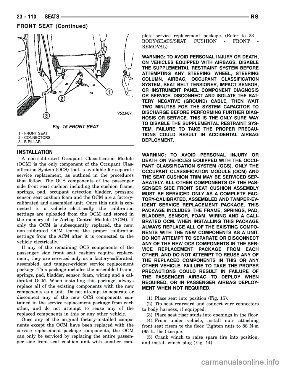
(1) Place seat into position (Fig. 15).
(2) Tip seat rearward and connect wire connectors
to body harness, if equipped.
(3) Place seat riser studs into openings in the floor.
(4) From under vehicle, install nuts attaching
front seat risers to the floor. Tighten nuts to 88 N´m
(65 ft. lbs.) torque.
(5) Crank winch to raise spare tire into position,
and install winch plug (Fig. 14).
Fig. 15 FRONT SEAT
1 - FRONT SEAT
2 - CONNECTORS
3 - B-PILLAR
23 - 110 SEATSRS
FRONT SEAT (Continued)
Page 1896 of 2339
(5) Install seat back panel (Fig. 23). (Refer to 23 -
BODY/SEATS/SEAT BACK - INSTALLATION).
(6) Install lumbar handle (Fig. 22).
(7) Install armrest cap and attaching bolt (Fig. 20)
and (Fig. 21).
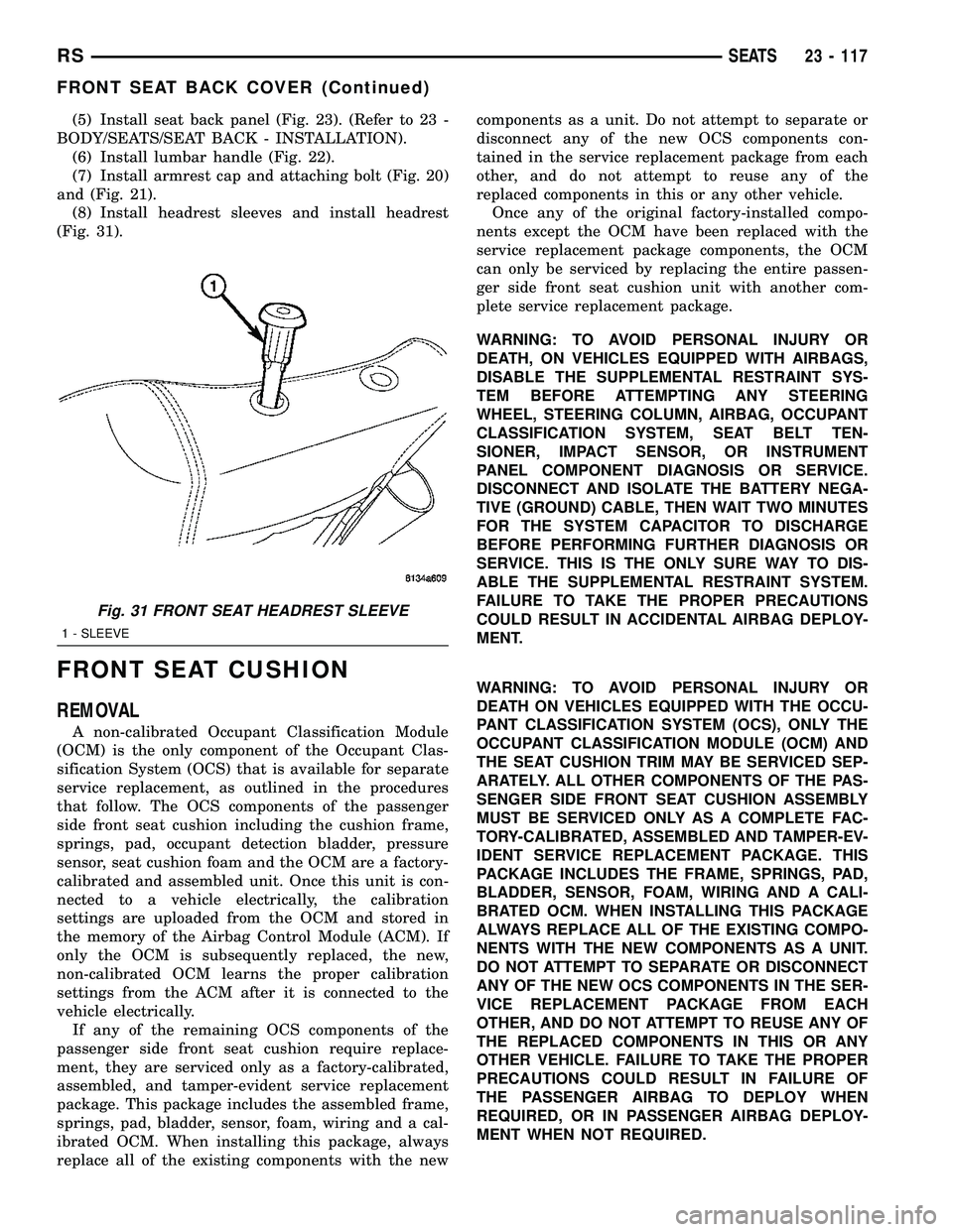
(8) Install headrest sleeves and install headrest
(Fig. 31).
FRONT SEAT CUSHION
REMOVAL
A non-calibrated Occupant Classification Module
(OCM) is the only component of the Occupant Clas-
sification System (OCS) that is available for separate
service replacement, as outlined in the procedures
that follow. The OCS components of the passenger
side front seat cushion including the cushion frame,
springs, pad, occupant detection bladder, pressure
sensor, seat cushion foam and the OCM are a factory-
calibrated and assembled unit. Once this unit is con-
nected to a vehicle electrically, the calibration
settings are uploaded from the OCM and stored in
the memory of the Airbag Control Module (ACM). If
only the OCM is subsequently replaced, the new,
non-calibrated OCM learns the proper calibration
settings from the ACM after it is connected to the
vehicle electrically.
If any of the remaining OCS components of the
passenger side front seat cushion require replace-
ment, they are serviced only as a factory-calibrated,
assembled, and tamper-evident service replacement
package. This package includes the assembled frame,
springs, pad, bladder, sensor, foam, wiring and a cal-
ibrated OCM. When installing this package, always
replace all of the existing components with the newcomponents as a unit. Do not attempt to separate or
disconnect any of the new OCS components con-
tained in the service replacement package from each
other, and do not attempt to reuse any of the
replaced components in this or any other vehicle.
Once any of the original factory-installed compo-
nents except the OCM have been replaced with the
service replacement package components, the OCM
can only be serviced by replacing the entire passen-
ger side front seat cushion unit with another com-
plete service replacement package.
WARNING: TO AVOID PERSONAL INJURY OR
DEATH, ON VEHICLES EQUIPPED WITH AIRBAGS,
DISABLE THE SUPPLEMENTAL RESTRAINT SYS-
TEM BEFORE ATTEMPTING ANY STEERING
WHEEL, STEERING COLUMN, AIRBAG, OCCUPANT
CLASSIFICATION SYSTEM, SEAT BELT TEN-
SIONER, IMPACT SENSOR, OR INSTRUMENT
PANEL COMPONENT DIAGNOSIS OR SERVICE.
DISCONNECT AND ISOLATE THE BATTERY NEGA-
TIVE (GROUND) CABLE, THEN WAIT TWO MINUTES
FOR THE SYSTEM CAPACITOR TO DISCHARGE
BEFORE PERFORMING FURTHER DIAGNOSIS OR
SERVICE. THIS IS THE ONLY SURE WAY TO DIS-
ABLE THE SUPPLEMENTAL RESTRAINT SYSTEM.
FAILURE TO TAKE THE PROPER PRECAUTIONS
COULD RESULT IN ACCIDENTAL AIRBAG DEPLOY-
MENT.
WARNING: TO AVOID PERSONAL INJURY OR
DEATH ON VEHICLES EQUIPPED WITH THE OCCU-
PANT CLASSIFICATION SYSTEM (OCS), ONLY THE
OCCUPANT CLASSIFICATION MODULE (OCM) AND
THE SEAT CUSHION TRIM MAY BE SERVICED SEP-
ARATELY. ALL OTHER COMPONENTS OF THE PAS-
SENGER SIDE FRONT SEAT CUSHION ASSEMBLY
MUST BE SERVICED ONLY AS A COMPLETE FAC-
TORY-CALIBRATED, ASSEMBLED AND TAMPER-EV-
IDENT SERVICE REPLACEMENT PACKAGE. THIS
PACKAGE INCLUDES THE FRAME, SPRINGS, PAD,
BLADDER, SENSOR, FOAM, WIRING AND A CALI-
BRATED OCM. WHEN INSTALLING THIS PACKAGE
ALWAYS REPLACE ALL OF THE EXISTING COMPO-
NENTS WITH THE NEW COMPONENTS AS A UNIT.
DO NOT ATTEMPT TO SEPARATE OR DISCONNECT
ANY OF THE NEW OCS COMPONENTS IN THE SER-
VICE REPLACEMENT PACKAGE FROM EACH
OTHER, AND DO NOT ATTEMPT TO REUSE ANY OF
THE REPLACED COMPONENTS IN THIS OR ANY
OTHER VEHICLE. FAILURE TO TAKE THE PROPER
PRECAUTIONS COULD RESULT IN FAILURE OF
THE PASSENGER AIRBAG TO DEPLOY WHEN
REQUIRED, OR IN PASSENGER AIRBAG DEPLOY-
MENT WHEN NOT REQUIRED.
Fig. 31 FRONT SEAT HEADREST SLEEVE
1 - SLEEVE
RSSEATS23 - 117
FRONT SEAT BACK COVER (Continued)
Page 1897 of 2339
(1) Remove seat cushion side covers, and leave
connector connected, if equipped. (Refer to 23 -
BODY/SEATS/FRONT SEAT CUSHION SIDE
COVER - REMOVAL)
(2) Remove seat track front and rear covers if
equipped. (Refer to 23 - BODY/SEATS/SEAT TRACK
REAR COVER - REMOVAL) and (Refer to 23 -
BODY/SEATS/SEAT TRACK FRONT COVER -
REMOVAL)
(3) If equipped, open storage bin to access front
pan bolts.
(4) Remove bolts attaching seat cushion pan to
seat track.
(5) Disconnect wire connectors, if equipment.
(6) Remove seat cushion from seat.
(7) Disengage J-strap retainers holding seat cover
to cushion.
(8) Remove seat cushion pan from cover and pad.
INSTALLATION
A non-calibrated Occupant Classification Module
(OCM) is the only component of the Occupant Clas-
sification System (OCS) that is available for separate
service replacement, as outlined in the procedures
that follow. The OCS components of the passenger
side front seat cushion including the cushion frame,
springs, pad, occupant detection bladder, pressure
sensor, seat cushion foam and the OCM are a factory-
calibrated and assembled unit. Once this unit is con-
nected to a vehicle electrically, the calibration
settings are uploaded from the OCM and stored in
the memory of the Airbag Control Module (ACM). If
only the OCM is subsequently replaced, the new,
non-calibrated OCM learns the proper calibration
settings from the ACM after it is connected to the
vehicle electrically.
If any of the remaining OCS components of the
passenger side front seat cushion require replace-
ment, they are serviced only as a factory-calibrated,
assembled, and tamper-evident service replacement
package. This package includes the assembled frame,
springs, pad, bladder, sensor, foam, wiring and a cal-
ibrated OCM. When installing this package, always
replace all of the existing components with the new
components as a unit. Do not attempt to separate or
disconnect any of the new OCS components con-
tained in the service replacement package from each
other, and do not attempt to reuse any of the
replaced components in this or any other vehicle.
Once any of the original factory-installed compo-
nents except the OCM have been replaced with the
service replacement package components, the OCM
can only be serviced by replacing the entire passen-
ger side front seat cushion unit with another com-
plete service replacement package.WARNING: TO AVOID PERSONAL INJURY OR
DEATH, ON VEHICLES EQUIPPED WITH AIRBAGS,
DISABLE THE SUPPLEMENTAL RESTRAINT SYS-
TEM BEFORE ATTEMPTING ANY STEERING
WHEEL, STEERING COLUMN, AIRBAG, OCCUPANT
CLASSIFICATION SYSTEM, SEAT BELT TEN-
SIONER, IMPACT SENSOR, OR INSTRUMENT
PANEL COMPONENT DIAGNOSIS OR SERVICE.
DISCONNECT AND ISOLATE THE BATTERY NEGA-
TIVE (GROUND) CABLE, THEN WAIT TWO MINUTES
FOR THE SYSTEM CAPACITOR TO DISCHARGE
BEFORE PERFORMING FURTHER DIAGNOSIS OR
SERVICE. THIS IS THE ONLY SURE WAY TO DIS-
ABLE THE SUPPLEMENTAL RESTRAINT SYSTEM.
FAILURE TO TAKE THE PROPER PRECAUTIONS
COULD RESULT IN ACCIDENTAL AIRBAG DEPLOY-
MENT.
WARNING: TO AVOID PERSONAL INJURY OR
DEATH ON VEHICLES EQUIPPED WITH THE OCCU-
PANT CLASSIFICATION SYSTEM (OCS), ONLY THE
OCCUPANT CLASSIFICATION MODULE (OCM) AND
THE SEAT CUSHION TRIM MAY BE SERVICED SEP-
ARATELY. ALL OTHER COMPONENTS OF THE PAS-
SENGER SIDE FRONT SEAT CUSHION ASSEMBLY
MUST BE SERVICED ONLY AS A COMPLETE FAC-
TORY-CALIBRATED, ASSEMBLED AND TAMPER-EV-
IDENT SERVICE REPLACEMENT PACKAGE. THIS
PACKAGE INCLUDES THE FRAME, SPRINGS, PAD,
BLADDER, SENSOR, FOAM, WIRING AND A CALI-
BRATED OCM. WHEN INSTALLING THIS PACKAGE
ALWAYS REPLACE ALL OF THE EXISTING COMPO-
NENTS WITH THE NEW COMPONENTS AS A UNIT.
DO NOT ATTEMPT TO SEPARATE OR DISCONNECT
ANY OF THE NEW OCS COMPONENTS IN THE SER-
VICE REPLACEMENT PACKAGE FROM EACH
OTHER, AND DO NOT ATTEMPT TO REUSE ANY OF
THE REPLACED COMPONENTS IN THIS OR ANY
OTHER VEHICLE. FAILURE TO TAKE THE PROPER
PRECAUTIONS COULD RESULT IN FAILURE OF
THE PASSENGER AIRBAG TO DEPLOY WHEN
REQUIRED, OR IN PASSENGER AIRBAG DEPLOY-
MENT WHEN NOT REQUIRED.
(1) Place seat cushion cover in position on seat
cushion.
(2) Engage J-strap retainers to hold seat cover to
cushion.
(3) Place seat cushion in position on seat.
(4) Connect wire connectors, if equipment.
(5) Install bolts attaching seat cushion to seat
track. Tighten bolts to 28.5 N´m (21 ft. lbs.) torque.
(6) If equipped, close storage bin.
23 - 118 SEATSRS
FRONT SEAT CUSHION (Continued)
Page 1898 of 2339
(7) Install seat track front and rear covers, if
equipped. (Refer to 23 - BODY/SEATS/SEAT TRACK
REAR COVER - INSTALLATION) and (Refer to 23 -
BODY/SEATS/SEAT TRACK FRONT COVER -
INSTALLATION)
(8) Install seat cushion side covers. (Refer to 23 -
BODY/SEATS/FRONT SEAT CUSHION SIDE
COVER - INSTALLATION)
FRONT SEAT CUSHION - OCS
REMOVAL
A non-calibrated Occupant Classification Module
(OCM) is the only component of the Occupant Clas-
sification System (OCS) that is available for separate
service replacement, as outlined in the procedures
that follow. The OCS components of the passenger
side front seat cushion including the cushion frame,
springs, pad, occupant detection bladder, pressure
sensor, seat cushion foam and the OCM are a factory-
calibrated and assembled unit. Once this unit is con-
nected to a vehicle electrically, the calibration
settings are uploaded from the OCM and stored in
the memory of the Airbag Control Module (ACM). If
only the OCM is subsequently replaced, the new,
non-calibrated OCM learns the proper calibration
settings from the ACM after it is connected to the
vehicle electrically.
If any of the remaining OCS components of the
passenger side front seat cushion require replace-
ment, they are serviced only as a factory-calibrated,
assembled, and tamper-evident service replacement
package. This package includes the assembled frame,
springs, pad, bladder, sensor, foam, wiring and a cal-
ibrated OCM. When installing this package, always
replace all of the existing components with the new
components as a unit. Do not attempt to separate or
disconnect any of the new OCS components con-
tained in the service replacement package from each
other, and do not attempt to reuse any of the
replaced components in this or any other vehicle.
Once any of the original factory-installed compo-
nents except the OCM have been replaced with the
service replacement package components, the OCM
can only be serviced by replacing the entire passen-
ger side front seat cushion unit with another com-
plete service replacement package.
WARNING: TO AVOID PERSONAL INJURY OR
DEATH, ON VEHICLES EQUIPPED WITH AIRBAGS,
DISABLE THE SUPPLEMENTAL RESTRAINT SYS-
TEM BEFORE ATTEMPTING ANY STEERING
WHEEL, STEERING COLUMN, AIRBAG, OCCUPANT
CLASSIFICATION SYSTEM, SEAT BELT TEN-
SIONER, IMPACT SENSOR, OR INSTRUMENT
PANEL COMPONENT DIAGNOSIS OR SERVICE.DISCONNECT AND ISOLATE THE BATTERY NEGA-
TIVE (GROUND) CABLE, THEN WAIT TWO MINUTES
FOR THE SYSTEM CAPACITOR TO DISCHARGE
BEFORE PERFORMING FURTHER DIAGNOSIS OR
SERVICE. THIS IS THE ONLY SURE WAY TO DIS-
ABLE THE SUPPLEMENTAL RESTRAINT SYSTEM.
FAILURE TO TAKE THE PROPER PRECAUTIONS
COULD RESULT IN ACCIDENTAL AIRBAG DEPLOY-
MENT.
WARNING: TO AVOID PERSONAL INJURY OR
DEATH ON VEHICLES EQUIPPED WITH THE OCCU-
PANT CLASSIFICATION SYSTEM (OCS), ONLY THE
OCCUPANT CLASSIFICATION MODULE (OCM) AND
THE SEAT CUSHION TRIM MAY BE SERVICED SEP-
ARATELY. ALL OTHER COMPONENTS OF THE PAS-
SENGER SIDE FRONT SEAT CUSHION ASSEMBLY
MUST BE SERVICED ONLY AS A COMPLETE FAC-
TORY-CALIBRATED, ASSEMBLED AND TAMPER-EV-
IDENT SERVICE REPLACEMENT PACKAGE. THIS
PACKAGE INCLUDES THE FRAME, SPRINGS, PAD,
BLADDER, SENSOR, FOAM, WIRING AND A CALI-
BRATED OCM. WHEN INSTALLING THIS PACKAGE
ALWAYS REPLACE ALL OF THE EXISTING COMPO-
NENTS WITH THE NEW COMPONENTS AS A UNIT.
DO NOT ATTEMPT TO SEPARATE OR DISCONNECT
ANY OF THE NEW OCS COMPONENTS IN THE SER-
VICE REPLACEMENT PACKAGE FROM EACH
OTHER, AND DO NOT ATTEMPT TO REUSE ANY OF
THE REPLACED COMPONENTS IN THIS OR ANY
OTHER VEHICLE. FAILURE TO TAKE THE PROPER
PRECAUTIONS COULD RESULT IN FAILURE OF
THE PASSENGER AIRBAG TO DEPLOY WHEN
REQUIRED, OR IN PASSENGER AIRBAG DEPLOY-
MENT WHEN NOT REQUIRED.
(1) Remove seat cushion side covers, and leave
connector connected, if equipped. (Refer to 23 -
BODY/SEATS/FRONT SEAT CUSHION SIDE
COVER - REMOVAL)
(2) Remove seat track front and rear covers if
equipped. (Refer to 23 - BODY/SEATS/SEAT TRACK
REAR COVER - REMOVAL) and (Refer to 23 -
BODY/SEATS/SEAT TRACK FRONT COVER -
REMOVAL)
(3) If equipped, open storage bin to access front
pan bolts.
(4) Remove bolts attaching seat cushion pan to
seat track.
(5) Disconnect wire connectors, if equipment.
(6) Remove seat cushion from seat.
(7) Disengage J-strap retainers holding seat cover
to cushion.
(8) Remove seat cushion pan from cover and pad.
RSSEATS23 - 119
FRONT SEAT CUSHION (Continued)
Page 1899 of 2339
INSTALLATION
A non-calibrated Occupant Classification Module
(OCM) is the only component of the Occupant Clas-
sification System (OCS) that is available for separate
service replacement, as outlined in the procedures
that follow. The OCS components of the passenger
side front seat cushion including the cushion frame,
springs, pad, occupant detection bladder, pressure
sensor, seat cushion foam and the OCM are a factory-
calibrated and assembled unit. Once this unit is con-
nected to a vehicle electrically, the calibration
settings are uploaded from the OCM and stored in
the memory of the Airbag Control Module (ACM). If
only the OCM is subsequently replaced, the new,
non-calibrated OCM learns the proper calibration
settings from the ACM after it is connected to the
vehicle electrically.
If any of the remaining OCS components of the
passenger side front seat cushion require replace-
ment, they are serviced only as a factory-calibrated,
assembled, and tamper-evident service replacement
package. This package includes the assembled frame,
springs, pad, bladder, sensor, foam, wiring and a cal-
ibrated OCM. When installing this package, always
replace all of the existing components with the new
components as a unit. Do not attempt to separate or
disconnect any of the new OCS components con-
tained in the service replacement package from each
other, and do not attempt to reuse any of the
replaced components in this or any other vehicle.
Once any of the original factory-installed compo-
nents except the OCM have been replaced with the
service replacement package components, the OCM
can only be serviced by replacing the entire passen-
ger side front seat cushion unit with another com-
plete service replacement package.
WARNING: TO AVOID PERSONAL INJURY OR
DEATH, ON VEHICLES EQUIPPED WITH AIRBAGS,
DISABLE THE SUPPLEMENTAL RESTRAINT SYS-
TEM BEFORE ATTEMPTING ANY STEERING
WHEEL, STEERING COLUMN, AIRBAG, OCCUPANT
CLASSIFICATION SYSTEM, SEAT BELT TEN-
SIONER, IMPACT SENSOR, OR INSTRUMENT
PANEL COMPONENT DIAGNOSIS OR SERVICE.
DISCONNECT AND ISOLATE THE BATTERY NEGA-
TIVE (GROUND) CABLE, THEN WAIT TWO MINUTES
FOR THE SYSTEM CAPACITOR TO DISCHARGE
BEFORE PERFORMING FURTHER DIAGNOSIS OR
SERVICE. THIS IS THE ONLY SURE WAY TO DIS-
ABLE THE SUPPLEMENTAL RESTRAINT SYSTEM.
FAILURE TO TAKE THE PROPER PRECAUTIONS
COULD RESULT IN ACCIDENTAL AIRBAG DEPLOY-
MENT.WARNING: TO AVOID PERSONAL INJURY OR
DEATH ON VEHICLES EQUIPPED WITH THE OCCU-
PANT CLASSIFICATION SYSTEM (OCS), ONLY THE
OCCUPANT CLASSIFICATION MODULE (OCM) AND
THE SEAT CUSHION TRIM MAY BE SERVICED SEP-
ARATELY. ALL OTHER COMPONENTS OF THE PAS-
SENGER SIDE FRONT SEAT CUSHION ASSEMBLY
MUST BE SERVICED ONLY AS A COMPLETE FAC-
TORY-CALIBRATED, ASSEMBLED AND TAMPER-EV-
IDENT SERVICE REPLACEMENT PACKAGE. THIS
PACKAGE INCLUDES THE FRAME, SPRINGS, PAD,
BLADDER, SENSOR, FOAM, WIRING AND A CALI-
BRATED OCM. WHEN INSTALLING THIS PACKAGE
ALWAYS REPLACE ALL OF THE EXISTING COMPO-
NENTS WITH THE NEW COMPONENTS AS A UNIT.
DO NOT ATTEMPT TO SEPARATE OR DISCONNECT
ANY OF THE NEW OCS COMPONENTS IN THE SER-
VICE REPLACEMENT PACKAGE FROM EACH
OTHER, AND DO NOT ATTEMPT TO REUSE ANY OF
THE REPLACED COMPONENTS IN THIS OR ANY
OTHER VEHICLE. FAILURE TO TAKE THE PROPER
PRECAUTIONS COULD RESULT IN FAILURE OF
THE PASSENGER AIRBAG TO DEPLOY WHEN
REQUIRED, OR IN PASSENGER AIRBAG DEPLOY-
MENT WHEN NOT REQUIRED.
(1) Place seat cushion cover in position on seat
cushion.
(2) Engage J-strap retainers to hold seat cover to
cushion.
(3) Place seat cushion in position on seat.
(4) Connect wire connectors, if equipment.
(5) Install bolts attaching seat cushion to seat
track. Tighten bolts to 28.5 N´m (21 ft. lbs.) torque.
(6) If equipped, close storage bin.
(7) Install seat track front and rear covers, if
equipped. (Refer to 23 - BODY/SEATS/SEAT TRACK
REAR COVER - INSTALLATION) and (Refer to 23 -
BODY/SEATS/SEAT TRACK FRONT COVER -
INSTALLATION)
(8) Install seat cushion side covers. (Refer to 23 -
BODY/SEATS/FRONT SEAT CUSHION SIDE
COVER - INSTALLATION)
FRONT SEAT CUSHION SIDE
COVER
REMOVAL
(1) Remove screws and plastic push pin attaching
seat cushion side cover to bucket seat (Fig. 32).
(2) Disengage J-strap along rear of seat cushion to
access screw.
(3) Remove screw attaching rear of side cover to
seat cushion frame.
(4) Remove side cover from seat cushion.
23 - 120 SEATSRS
FRONT SEAT CUSHION - OCS (Continued)
Page 2321 of 2339

LWB - INSTALLATION, SEAT BELT &RETRACTOR - SECOND ROW - RIGHT
OUTBOARD WITH REAR HVAC ..........8O-41
LWB - REMOVAL, SEAT BELT & RETRACTOR - SECOND ROW - RIGHT
OUTBOARD WITH REAR HVAC ..........8O-41
MACHINING - STANDARD PROCEDURE, BRAKE ROTOR ....................... 5-58
MAIN BEARING FITTING - STANDARD PROCEDURE ........................ 9-125
MAIN BEARINGS - INSTALLATION, CRANKSHAFT ....................... 9-127
MAIN BEARINGS - REMOVAL, CRANKSHAFT ....................... 9-127
MANAGER - DESCRIPTION, TASK ........25-25
MANAGER - OPERATION, TASK .........25-25
MANIFOLD - CLEANING, EXHAUST ........9-63
MANIFOLD - DESCRIPTION, INTAKE . . 9-147,9-60
MANIFOLD - INSPECTION, EXHAUST ......9-63
MANIFOLD - INSTALLATION, EXHAUST ....9-63
MANIFOLD - INSTALLATION, LOWER INTAKE ............................ 9-151
MANIFOLD - INSTALLATION, UPPER INTAKE ............................ 9-149
MANIFOLD - LEFT - CLEANING, EXHAUST ........................... 9-154
MANIFOLD - LEFT - INSPECTION, EXHAUST ........................... 9-155
MANIFOLD - LEFT - INSTALLATION, EXHAUST ........................... 9-155
MANIFOLD - LEFT - REMOVAL, EXHAUST . 9-154
MANIFOLD - LOWER - CLEANING, INTAKE ............................ 9-151
MANIFOLD - LOWER - INSPECTION, INTAKE ........................ 9-151,9-62
MANIFOLD - LOWER - INSTALLATION, INTAKE ............................. 9-62
MANIFOLD - LOWER - REMOVAL, INTAKE ............................. 9-62
MANIFOLD - REMOVAL, EXHAUST ........9-63
MANIFOLD - REMOVAL, LOWER INTAKE . . 9-150
MANIFOLD - REMOVAL, UPPER INTAKE . . . 9-148
MANIFOLD - RIGHT - CLEANING, EXHAUST ........................... 9-153
MANIFOLD - RIGHT - INSPECTION, EXHAUST ........................... 9-153
MANIFOLD - RIGHT - INSTALLATION, EXHAUST ........................... 9-153
MANIFOLD - RIGHT - REMOVAL, EXHAUST ........................... 9-152
MANIFOLD - UPPER - INSPECTION, INTAKE ............................. 9-61
MANIFOLD - UPPER - INSTALLATION, INTAKE ............................. 9-61
MANIFOLD - UPPER - REMOVAL, INTAKE . . 9-60
MANIFOLD LEAKS - DIAGNOSIS AND TESTING, INTAKE ................ 9-147,9-60
MANIFOLD STRIPPED THREAD REPAIR - STANDARD PROCEDURE ...............9-147
MANIFOLD VACUUM PORT REPAIR - STANDARD PROCEDURE, INTAKE ........9-148
MANUAL - INSTALLATION, WINDOW REGULATOR ........................ 23-23
MANUAL - OCS - INSTALLATION, FRONT SEAT RISER ........................ 23-123
MANUAL - OCS - REMOVAL, FRONT SEAT RISER ........................ 23-123
MANUAL - REMOVAL, WINDOW REGULATOR ........................ 23-22
MANUAL ADJUSTER - INSTALLATION, FRONT SEAT TRACK .................23-126
MANUAL ADJUSTER - REMOVAL, FRONT SEAT TRACK ....................... 23-125
MANUAL DUAL ZONE, DESCRIPTION ......24-2
MANUAL DUAL ZONE, OPERATION ........24-5
MANUAL SINGLE ZONE, DESCRIPTION ....24-2
MANUAL SINGLE ZONE, OPERATION ......24-4
MANUAL TEMPERATURE CONTROL SYSTEM, OPERATION ................24-113
MANUAL THREE ZONE, DESCRIPTION .....24-2
MANUAL THREE ZONE, OPERATION .......24-5
MAP SENSOR - DESCRIPTION ..........14-34
MAP SENSOR - OPERATION ............14-34
MASTER CYLINDER BLEEDING - STANDARD PROCEDURE ................5-36
MASTER CYLINDER (FLUID RESERVOIR) - ASSEMBLY ......................... 5-39MASTER CYLINDER (FLUID RESERVOIR)
- DISASSEMBLY ...................... 5-38
MATCH MOUNTING - STANDARD PROCEDURE, TIRE AND WHEEL ..........22-7
MATS - INSTALLATION, CARPETS AND FLOOR ............................. 23-81
MATS - REMOVAL, CARPETS AND FLOOR ............................. 23-81
MEASUREMENT - STANDARD PROCEDURE, CURB HEIGHT .............2-55
MEASUREMENT AND ADJUSTMENT, ADJUSTMENTS - DIFFERENTIAL
BEARING PRELOAD ................... 21-79
MEASUREMENTS - SPECIFICATIONS, GAP AND FLUSH .................... 23-177
MEASURING BEARING CLEARANCE USING PLASTIGAGE - STANDARD
PROCEDURE ..................... 9-12,9-86
MEASURING CAMSHAFT END PLAY - STANDARD PROCEDURE ................9-29
MEASURING CONNECTING ROD BEARING CLEARANCE - STANDARD
PROCEDURE ........................ 9-123
MEASURING CRANKSHAFT END PLAY - STANDARD PROCEDURE ...............9-128
MEASURING TIMING CHAIN WEAR - STANDARD PROCEDURE ...............9-155
MECHANICAL - DIAGNOSIS AND TESTING, ENGINE DIAGNOSIS ........9-6,9-82
MECHANISM -SECOND ROW -FOLD-IN- FLOOR - INSTALLATION, SEAT
RECLINER/FORWARD FOLDING ........23-137
MECHANISM -SECOND ROW -FOLD-IN- FLOOR - REMOVAL, SEAT RECLINER/
FORWARD FOLDING .................23-137
MECHANISM -THIRD ROW -FOLD-IN- FLOOR - INSTALLATION, SEAT
RECLINER/FOLD FORWARD ...........23-160
MECHANISM -THIRD ROW -FOLD-IN- FLOOR - REMOVAL, SEAT RECLINER/
FOLD FORWARD .................... 23-160
MEMORIES, OPERATION - FUEL CORRECTION OR ADAPTIVE ............14-24
MEMORY SEAT/MIRROR MODULE - DESCRIPTION ........................ 8E-9
MEMORY SEAT/MIRROR MODULE - OPERATION .......................... 8E-9
MEMORY SEAT/MIRROR MODULE, DIAGNOSIS AND TESTING ..............8E-9
MEMORY SWITCH - DESCRIPTION ......8N-36
MEMORY SWITCH - OPERATION ........8N-36
MEMORY SWITCH, DIAGNOSIS AND TESTING ........................... 8N-37
MEMORY SYSTEM, DESCRIPTION .......8N-32
MEMORY SYSTEM, DIAGNOSIS AND TESTING ........................... 8N-33
MEMORY SYSTEM, OPERATION .........8N-33
MESSAGE CENTER - INSTALLATION ......8M-1
MESSAGE CENTER - REMOVAL ..........8M-1
MICRO 420 BATTERY TESTER, STANDARD PROCEDURE ...............8F-15
MINI-TRIP COMPUTER, DIAGNOSIS AND TESTING - COMPASS .................8M-10
MIRROR - DESCRIPTION, AUTOMATIC DAY / NIGHT ........................ 8N-28
MIRROR - INSTALLATION, GLASS- OUTSIDE REARVIEW .................. 23-61
MIRROR - INSTALLATION, REAR VIEW . . . 23-97
MIRROR - INSTALLATION, SIDE VIEW ....23-60
MIRROR - OPERATION, AUTOMATIC DAY / NIGHT ............................ 8N-28
MIRROR - REMOVAL, GLASS-OUTSIDE REARVIEW .......................... 23-61
MIRROR - REMOVAL, REAR VIEW .......23-97
MIRROR - REMOVAL, SIDE VIEW ........23-60
MIRROR - REMOVAL, SIDEVIEW ........8N-30
MIRROR, DIAGNOSIS AND TESTING - AUTOMATIC DAY / NIGHT ..............8N-28
MIRROR SWITCH - EXPORT - DESCRIPTION, POWER FOLDAWAY ......8N-29
MIRROR SWITCH - EXPORT - INSTALLATION, POWER FOLDAWAY ......8N-30
MIRROR SWITCH - EXPORT - OPERATION, POWER FOLDAWAY ........8N-29
MIRROR SWITCH - EXPORT - REMOVAL, POWER FOLDAWAY .................. 8N-29
MIRRORS - DESCRIPTION, HEATED .......8G-6
MIRRORS - DESCRIPTION, POWER ......8N-26 MIRRORS - OPERATION, HEATED
........8G-6
MIRRORS - OPERATION, POWER ........8N-26
MIRRORS, DIAGNOSIS AND TESTING - POWER ............................ 8N-27
MODE DOOR ACTUATOR - DESCRIPTION . . 24-29
MODE DOOR ACTUATOR - INSTALLATION ....................... 24-30
MODE DOOR ACTUATOR - OPERATION . . . 24-29
MODE DOOR ACTUATOR - REAR - DESCRIPTION ....................... 24-39
MODE DOOR ACTUATOR - REAR - INSTALLATION ....................... 24-40
MODE DOOR ACTUATOR - REAR - OPERATION ......................... 24-39
MODE DOOR ACTUATOR - REAR - REMOVAL .......................... 24-39
MODE DOOR ACTUATOR - REMOVAL .....24-29
MODE, OPERATION - DRB III TS TAT E
DISPLAY TEST ....................... 25-10
MODELS, INSTALLATION - RG ..........24-27
MODELS, INSTALLATION - RS ..........24-28
MODELS, REMOVAL - RG ..............24-27
MODELS, REMOVAL - RS ..............24-27
MODES OF OPERATION - OPERATION ....14-22
MODULE - BLOWER MOTOR - DESCRIPTION, POWER ................24-30
MODULE - BLOWER MOTOR - INSTALLATION, POWER ...............24-31
MODULE - BLOWER MOTOR - OPERATION, POWER .................. 24-30
MODULE - BLOWER MOTOR - REMOVAL, POWER ................... 24-30
MODULE - DESCRIPTION, BODY CONTROL ........................... 8E-2
MODULE - DESCRIPTION, FRONT CONTROL ........................... 8E-7
MODULE - DESCRIPTION, FUEL PUMP ....14-8
MODULE - DESCRIPTION, HEATED SEAT . . . 8E-8
MODULE - DESCRIPTION, INTEGRATED POWER ..........................8W -97-1
MODULE - DESCRIPTION, MEMORY SEAT/MIRROR ........................ 8E-9
MODULE - DESCRIPTION, OCCUPANT CLASSIFICATION ..................... 8O-25
MODULE - DESCRIPTION, PARK ASSIST . . . 8B-4
MODULE - DESCRIPTION, POWER LIFTGATE CONTROL .................. 8E-10
MODULE - DESCRIPTION, SENTRY KEY REMOTE ENTRY ...................... 8Q-3
MODULE - DESCRIPTION, SLIDING DOOR CONTROL ..................... 8E-18
MODULE - DIAGNOSIS AND TESTING, SENTRY KEY REMOTE ENTRY ...........8Q-5
MODULE - EXPORT - DESCRIPTION, ANTENNA .......................... 8A-10
MODULE - EXPORT - OPERATION, ANTENNA .......................... 8A-10
MODULE - INSTALLATION, BODY CONTROL ........................... 8E-4
MODULE - INSTALLATION, HANDS FREE . . . 8T-3
MODULE - INSTALLATION, INTEGRATED POWER ..........................8W -97-2
MODULE - INSTALLATION, OCCUPANT CLASSIFICATION ..................... 8O-26
MODULE - INSTALLATION, PARK ASSIST . . 8B-6
MODULE - INSTALLATION, SENTRY KEY REMOTE ENTRY ...................... 8Q-6
MODULE - INSTALLATION, WIPER .......8R-14
MODULE - OPERATION, BODY CONTROL . . . 8E-3
MODULE - OPERATION, FRONT CONTROL ........................... 8E-7
MODULE - OPERATION, FUEL PUMP ......14-9
MODULE - OPERATION, HEATED SEAT .....8E-8
MODULE - OPERATION, INTEGRATED POWER ..........................8W -97-2
MODULE - OPERATION, MEMORY SEAT/MIRROR ........................ 8E-9
MODULE - OPERATION, OCCUPANT CLASSIFICATION ..................... 8O-25
MODULE - OPERATION, PARK ASSIST .....8B-5
MODULE - OPERATION, POWER LIFTGATE CONTROL .................. 8E-10
MODULE - OPERATION, SENTRY KEY REMOTE ENTRY ...................... 8Q-4
MODULE - OPERATION, SLIDING DOOR CONTROL .......................... 8E-18
MODULE - REAR BLOWER MOTOR - DESCRIPTION, POWER ................24-40
20 INDEXRS
Description Group-Page Description Group-Page Description Group-Page