2005 CHRYSLER VOYAGER brakes fluid
[x] Cancel search: brakes fluidPage 212 of 2339
For more information, (Refer to 5 - BRAKES/HY-
DRAULIC/MECHANICAL/ICU (INTEGRATED CON-
TROL UNIT) - DESCRIPTION)
OPERATION
For information on the operation of the HCU as a
whole, refer to Hydraulic Circuits And Valve Opera-
tion which can be found elsewhere in this section.
For information on the operation of the components
within the HCU, refer to the following three topics.
VALVES AND SOLENOIDS
The valve block contains four inlet valves and four
outlet valves. The inlet valves are spring-loaded in
the open position and the outlet valves are spring-
loaded in the closed position during normal braking.
The fluid is allowed to flow from the master cylinder
to the wheel brakes.
During an ABS stop, these valves cycle to maintain
the proper slip ratio for each wheel. The inlet valve
closes preventing further pressure increase and the
outlet valve opens to provide a path from the wheel
brake to the HCU accumulators and pump/motor.
This releases (decays) pressure from the wheel brake,
thus releasing the wheel from excessive slippage.
Once the wheel is no longer slipping, the outlet valve
is closed and the inlet valve is opened to reapply
(build) pressure.
On vehicles with traction control, there is an extra
set of valves and solenoids. The ASR valves, mounted
in the HCU valve block, are normally in the open
position and close only when the traction control is
applied.
These isolator valves are used to isolate the rear
(non-driving) wheels of the vehicle from the hydraulic
pressure that the HCU pump/motor is sending to the
front (driving) wheels when traction control is being
applied. The rear brakes need to be isolated from the
master cylinder when traction control is being
applied so the rear wheels do not drag. For more
information, refer to Traction Control System in this
section.
BRAKE FLUID ACCUMULATORS
There are two fluid accumulators in the HCU±one
for the primary hydraulic circuit and one for the sec-
ondary hydraulic circuit. Each hydraulic circuit uses
a 5 cc accumulator.
The fluid accumulators temporarily store brake
fluid that is removed from the wheel brakes during
an ABS cycle. This stored fluid is used by the pump/
motor to provide build pressure for the brake hydrau-
lic system. When the antilock stop is complete, the
accumulators are drained by the pump/motor.
On ABS-only vehicles, there is a mini-accumulator
on the secondary hydraulic circuit that protects the
master cylinder seals during an ABS stop, and there
is a noise dampening chamber on the primary circuit.
On ABS with traction control vehicles, there are
two noise dampening chambers in the HCU.
PUMP/MOTOR
There are two pump assemblies in the HCUÐone
for the primary hydraulic circuit and one for the sec-
ondary hydraulic circuit. Both pumps are driven by a
common electric motor. This DC-type motor is inte-
gral to the HCU and is controlled by the CAB.
The pump/motor provides the extra amount of
brake fluid needed during antilock braking. Brake
fluid is released to the accumulators when the outlet
valve is opened during an antilock stop. The pump
mechanism consists of two opposing pistons operated
by an eccentric camshaft. In operation, one piston
draws fluid from the accumulators, and the opposing
piston pumps fluid to the master cylinder circuits.
When the antilock stop is complete, the pump/motor
drains the accumulators.
The CAB may turn on the pump/motor when an
antilock stop is detected. The pump/motor continues
to run during the antilock stop and is turned off after
the stop is complete. Under some conditions, the
pump/motor runs to drain the accumulators during
the next drive-off.
The pump/motor is not a serviceable item; if it
requires replacement, the HCU must be replaced.
RSBRAKES - ABS5 - 101
HCU (HYDRAULIC CONTROL UNIT) (Continued)
Page 213 of 2339
ICU (INTEGRATED CONTROL
UNIT)
DESCRIPTION
The hydraulic control unit (HCU) and the control-
ler antilock brake (CAB) used with this antilock
brake system are combined (integrated) into one
unit, which is called the integrated control unit (ICU)
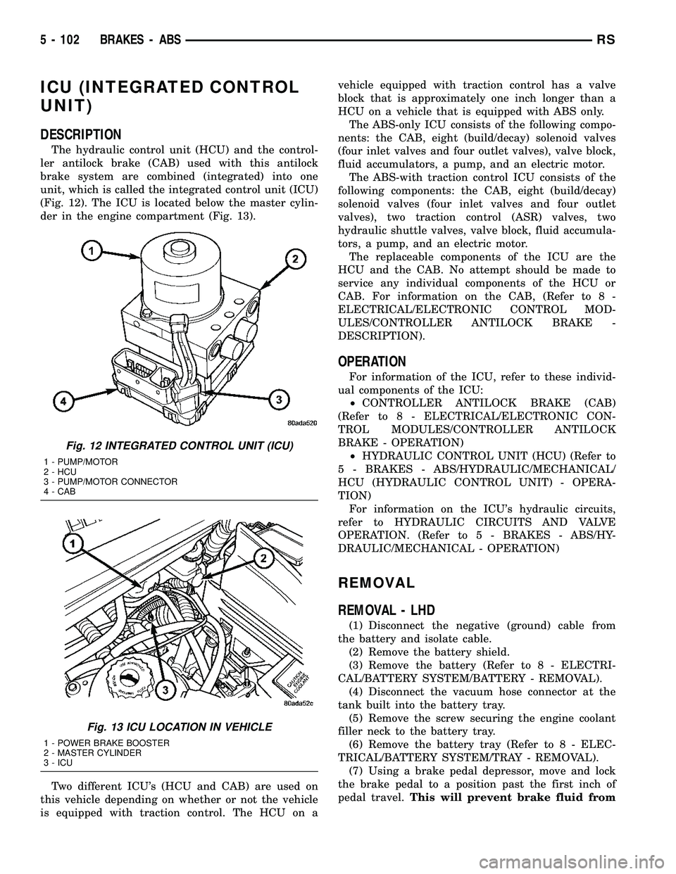
(Fig. 12). The ICU is located below the master cylin-
der in the engine compartment (Fig. 13).
Two different ICU's (HCU and CAB) are used on
this vehicle depending on whether or not the vehicle
is equipped with traction control. The HCU on avehicle equipped with traction control has a valve
block that is approximately one inch longer than a
HCU on a vehicle that is equipped with ABS only.
The ABS-only ICU consists of the following compo-
nents: the CAB, eight (build/decay) solenoid valves
(four inlet valves and four outlet valves), valve block,
fluid accumulators, a pump, and an electric motor.
The ABS-with traction control ICU consists of the
following components: the CAB, eight (build/decay)
solenoid valves (four inlet valves and four outlet
valves), two traction control (ASR) valves, two
hydraulic shuttle valves, valve block, fluid accumula-
tors, a pump, and an electric motor.
The replaceable components of the ICU are the
HCU and the CAB. No attempt should be made to
service any individual components of the HCU or
CAB. For information on the CAB, (Refer to 8 -
ELECTRICAL/ELECTRONIC CONTROL MOD-
ULES/CONTROLLER ANTILOCK BRAKE -
DESCRIPTION).
OPERATION
For information of the ICU, refer to these individ-
ual components of the ICU:
²CONTROLLER ANTILOCK BRAKE (CAB)
(Refer to 8 - ELECTRICAL/ELECTRONIC CON-
TROL MODULES/CONTROLLER ANTILOCK
BRAKE - OPERATION)
²HYDRAULIC CONTROL UNIT (HCU) (Refer to
5 - BRAKES - ABS/HYDRAULIC/MECHANICAL/
HCU (HYDRAULIC CONTROL UNIT) - OPERA-
TION)
For information on the ICU's hydraulic circuits,
refer to HYDRAULIC CIRCUITS AND VALVE
OPERATION. (Refer to 5 - BRAKES - ABS/HY-
DRAULIC/MECHANICAL - OPERATION)
REMOVAL
REMOVAL - LHD
(1) Disconnect the negative (ground) cable from
the battery and isolate cable.
(2) Remove the battery shield.
(3) Remove the battery (Refer to 8 - ELECTRI-
CAL/BATTERY SYSTEM/BATTERY - REMOVAL).
(4) Disconnect the vacuum hose connector at the
tank built into the battery tray.
(5) Remove the screw securing the engine coolant
filler neck to the battery tray.
(6) Remove the battery tray (Refer to 8 - ELEC-
TRICAL/BATTERY SYSTEM/TRAY - REMOVAL).
(7) Using a brake pedal depressor, move and lock
the brake pedal to a position past the first inch of
pedal travel.This will prevent brake fluid from
Fig. 12 INTEGRATED CONTROL UNIT (ICU)
1 - PUMP/MOTOR
2 - HCU
3 - PUMP/MOTOR CONNECTOR
4 - CAB
Fig. 13 ICU LOCATION IN VEHICLE
1 - POWER BRAKE BOOSTER
2 - MASTER CYLINDER
3 - ICU
5 - 102 BRAKES - ABSRS
Page 215 of 2339
CHANICAL/ICU (INTEGRATED CONTROL UNIT) -
DISASSEMBLY).
REMOVAL - RHD
NOTE: Before proceeding, (Refer to 5 - BRAKES -
WARNING)(Refer to 5 - BRAKES - CAUTION)
(1) Disconnect the negative (ground) cable from
the battery and isolate cable.
(2) Using a brake pedal depressor, move and lock
the brake pedal to a position past the first inch of
pedal travel.This will prevent brake fluid from
draining out of the master cylinder when the
brake tubes are removed from the HCU.
(3) Raise vehicle. (Refer to LUBRICATION &
MAINTENANCE/HOISTING - STANDARD PROCE-
DURE)
(4) Remove the routing clip attaching the ICU wir-
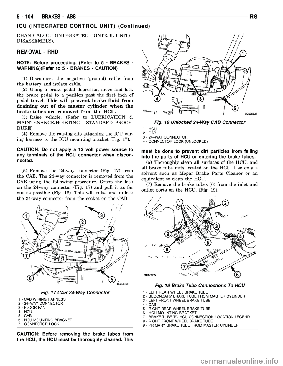
ing harness to the ICU mounting bracket (Fig. 17).
CAUTION: Do not apply a 12 volt power source to
any terminals of the HCU connector when discon-
nected.
(5) Remove the 24-way connector (Fig. 17) from
the CAB. The 24-way connector is removed from the
CAB using the following procedure. Grasp the lock
on the 24-way connector (Fig. 17) and pull it as far
out as possible (Fig. 18). This will raise and unlock
the 24-way connector from the socket on the CAB.
CAUTION: Before removing the brake tubes from
the HCU, the HCU must be thoroughly cleaned. Thismust be done to prevent dirt particles from falling
into the ports of HCU or entering the brake tubes.
(6) Thoroughly clean all surfaces of the HCU, and
all brake tube nuts located on the HCU. Use only a
solvent such as Mopar Brake Parts Cleaner or an
equivalent to clean the HCU.
(7) Remove the brake tubes (6) from the inlet and
outlet ports on the HCU. (Fig. 19).
Fig. 17 CAB 24-Way Connector
1 - CAB WIRING HARNESS
2 - 24±WAY CONNECTOR
3 - FLOOR PAN
4 - HCU
5 - CAB
6 - HCU MOUNTING BRACKET
7 - CONNECTOR LOCK
Fig. 18 Unlocked 24-Way CAB Connector
1 - HCU
2 - CAB
3 - 24±WAY CONNECTOR
4 - CONNECTOR LOCK (UNLOCKED)
Fig. 19 Brake Tube Connections To HCU
1 - LEFT REAR WHEEL BRAKE TUBE
2 - SECONDARY BRAKE TUBE FROM MASTER CYLINDER
3 - LEFT FRONT WHEEL BRAKE TUBE
4 - CAB
5 - RIGHT REAR WHEEL BRAKE TUBE
6 - HCU MOUNTING BRACKET
7 - BRAKE TUBE TO HCU CONNECTION LOCATION LEGEND
8 - RIGHT FRONT WHEEL BRAKE TUBE
9 - PRIMARY BRAKE TUBE FROM MASTER CYLINDER
5 - 104 BRAKES - ABSRS
ICU (INTEGRATED CONTROL UNIT) (Continued)
Page 290 of 2339

trical connector on the vehicle wiring harness. The
power source for the CAB is through the ignition
switch in the RUN or ON position. The CAB is on
the PCI bus.
OPERATION
The primary functions of the controller antilock
brake (CAB) are to:
²Monitor the antilock brake system for proper
operation.
²Detect wheel locking or wheel slipping tenden-
cies by monitoring the speed of all four wheels of the
vehicle.
²Control fluid modulation to the wheel brakes
while the system is in an ABS mode.
²Store diagnostic information.
²Provide communication to the DRBIIItscan tool
while in diagnostic mode.
²Illuminate the amber ABS warning indicator
lamp.
²(With traction control only) Illuminate the TRAC
ON lamp in the message center on the instrument
panel when a traction control event occurs.
²(with traction control only) Illuminate the TRAC
OFF lamp when the amber ABS warning indicator
lamp illuminates.
The CAB constantly monitors the antilock brake
system for proper operation. If the CAB detects a
fault, it will turn on the amber ABS warning indica-
tor lamp and disable the antilock braking system.
The normal base braking system will remain opera-
tional.
NOTE: If the vehicle is equipped with traction con-
trol, the TRAC OFF lamp will illuminate anytime the
amber ABS warning indicator lamp illuminates.The CAB continuously monitors the speed of each
wheel through the signals generated by the wheel
speed sensors to determine if any wheel is beginning
to lock. When a wheel locking tendency is detected,
the CAB commands the CAB command coils to actu-
ate. The coils then open and close the valves in the
HCU that modulate brake fluid pressure in some or
all of the hydraulic circuits. The CAB continues to
control pressure in individual hydraulic circuits until
a locking tendency is no longer present.
The CAB contains a self-diagnostic program that
monitors the antilock brake system for system faults.
When a fault is detected, the amber ABS warning
indicator lamp is turned on and the fault diagnostic
trouble code (DTC) is then stored in a diagnostic pro-
gram memory. A latched fault will disable certain
system functionality for the current ignition cycle. An
unlatched fault will disable certain system function-
ality until the fault condition disappears. These
DTC's will remain in the CAB memory even after the
ignition has been turned off. The DTC's can be read
and cleared from the CAB memory by a technician
using the DRBIIItscan tool. If not cleared with a
DRBIIItscan tool, the fault occurrence and DTC will
be automatically cleared from the CAB memory after
the identical fault has not been seen during the next
3,500 miles. Drive-off may be required for the amber
ABS warning indicator lamp to go out on the next
ignition cycle.
CAB INPUTS
²Wheel speed sensors (four)
²Brake lamp switch
²Ignition switch
²System and pump voltage
²Ground
²Traction control switch (if equipped)
²Diagnostic communication (PCI)
CAB OUTPUTS
²Amber ABS warning indicator lamp actuation
(via BUS)
²Red BRAKE warning indicator lamp actuation
(via BUS)
²Instrument cluster (MIC) communication (PCI)
²Traction control lamps (if equipped)
²Diagnostic communication (PCI, via BUS)
REMOVAL
(1) Disconnect the battery cables.
(2) Remove the battery (Refer to 8 - ELECTRI-
CAL/BATTERY SYSTEM/BATTERY - REMOVAL).
(3) Disconnect the vacuum hose connector at the
tank built into the battery tray.
(4) Remove the screw securing the coolant filler
neck to the battery tray.
Fig. 1 Integrated Control Unit (ICU)
1 - PUMP/MOTOR
2 - HCU
3 - PUMP/MOTOR CONNECTOR
4 - CAB
RSELECTRONIC CONTROL MODULES8E-5
CONTROLLER ANTILOCK BRAKE (Continued)
Page 750 of 2339

8W-35 ANTILOCK BRAKES
Component Page
Body Control Module................. 8W-35-2
Brake Fluid Level Switch.............. 8W-35-3
Brake Lamp Switch.................. 8W-35-3
Clutch Pedal Interlock Switch.......... 8W-35-3
Controller Antilock Brake.......... 8W-35-2, 3, 4
Engine Control Module................ 8W-35-3
Front Control Module................. 8W-35-3
Fuse 9............................ 8W-35-2
Fuse 21............................ 8W-35-2
Fuse 26............................ 8W-35-3
G100.............................. 8W-35-2Component Page
G200.............................. 8W-35-2
G300.............................. 8W-35-3
Integrated Power Module............ 8W-35-2, 3
Left Front Wheel Speed Sensor......... 8W-35-4
Left Rear Wheel Speed Sensor.......... 8W-35-4
Powertrain Control Module............ 8W-35-3
Right Front Wheel Speed Sensor........ 8W-35-4
Right Rear Wheel Speed Sensor......... 8W-35-4
Traction Control Switch............... 8W-35-2
Transmission Control Module........... 8W-35-3
RS8W-35 ANTILOCK BRAKES8W-35-1
Page 1545 of 2339
(6) Start engine and allow to idle for at least one
minute. Then, with parking and service brakes
applied, move selector lever momentarily to each
position, ending in the park or neutral position.
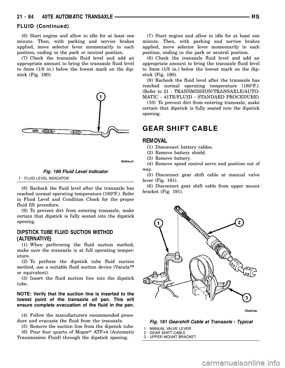
(7) Check the transaxle fluid level and add an
appropriate amount to bring the transaxle fluid level
to 3mm (1/8 in.) below the lowest mark on the dip-
stick (Fig. 190).
(8) Recheck the fluid level after the transaxle has
reached normal operating temperature (180ÉF.). Refer
to Fluid Level and Condition Check for the proper
fluid fill procedure.
(9) To prevent dirt from entering transaxle, make
certain that dipstick is fully seated into the dipstick
opening.
DIPSTICK TUBE FLUID SUCTION METHOD
(ALTERNATIVE)
(1) When performing the fluid suction method,
make sure the transaxle is at full operating temper-
ature.
(2) To perform the dipstick tube fluid suction
method, use a suitable fluid suction device (VaculaŸ
or equivalent).
(3) Insert the fluid suction line into the dipstick
tube.
NOTE: Verify that the suction line is inserted to the
lowest point of the transaxle oil pan. This will
ensure complete evacuation of the fluid in the pan.
(4) Follow the manufacturers recommended proce-
dure and evacuate the fluid from the transaxle.
(5) Remove the suction line from the dipstick tube.
(6) Pour four quarts of MopartATF+4 (Automatic
Transmission Fluid) through the dipstick opening.(7) Start engine and allow to idle for at least one
minute. Then, with parking and service brakes
applied, move selector lever momentarily to each
position, ending in the park or neutral position.
(8) Check the transaxle fluid level and add an
appropriate amount to bring the transaxle fluid level
to 3mm (1/8 in.) below the lowest mark on the dip-
stick (Fig. 190).
(9) Recheck the fluid level after the transaxle has
reached normal operating temperature (180ÉF.).
(Refer to 21 - TRANSMISSION/TRANSAXLE/AUTO-
MATIC - 41TE/FLUID - STANDARD PROCEDURE)
(10) To prevent dirt from entering transaxle, make
certain that dipstick is fully seated into the dipstick
opening.
GEAR SHIFT CABLE
REMOVAL
(1) Disconnect battery cables.
(2) Remove battery shield.
(3) Remove battery.
(4) Remove speed control servo and position out of
way.
(5) Disconnect gear shift cable at manual valve
lever (Fig. 191).
(6) Disconnect gear shift cable from upper mount
bracket (Fig. 191).
Fig. 190 Fluid Level Indicator
1 - FLUID LEVEL INDICATOR
Fig. 191 Gearshift Cable at Transaxle - Typical
1 - MANUAL VALVE LEVER
2 - GEAR SHIFT CABLE
3 - UPPER MOUNT BRACKET
21 - 84 40TE AUTOMATIC TRANSAXLERS
FLUID (Continued)
Page 1693 of 2339
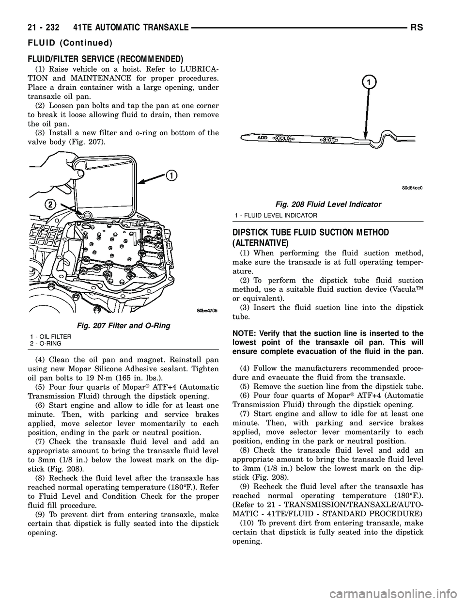
FLUID/FILTER SERVICE (RECOMMENDED)
(1) Raise vehicle on a hoist. Refer to LUBRICA-
TION and MAINTENANCE for proper procedures.
Place a drain container with a large opening, under
transaxle oil pan.
(2) Loosen pan bolts and tap the pan at one corner
to break it loose allowing fluid to drain, then remove
the oil pan.
(3) Install a new filter and o-ring on bottom of the
valve body (Fig. 207).
(4) Clean the oil pan and magnet. Reinstall pan
using new Mopar Silicone Adhesive sealant. Tighten
oil pan bolts to 19 N´m (165 in. lbs.).
(5) Pour four quarts of MopartATF+4 (Automatic
Transmission Fluid) through the dipstick opening.
(6) Start engine and allow to idle for at least one
minute. Then, with parking and service brakes
applied, move selector lever momentarily to each
position, ending in the park or neutral position.
(7) Check the transaxle fluid level and add an
appropriate amount to bring the transaxle fluid level
to 3mm (1/8 in.) below the lowest mark on the dip-
stick (Fig. 208).
(8) Recheck the fluid level after the transaxle has
reached normal operating temperature (180ÉF.). Refer
to Fluid Level and Condition Check for the proper
fluid fill procedure.
(9) To prevent dirt from entering transaxle, make
certain that dipstick is fully seated into the dipstick
opening.
DIPSTICK TUBE FLUID SUCTION METHOD
(ALTERNATIVE)
(1) When performing the fluid suction method,
make sure the transaxle is at full operating temper-
ature.
(2) To perform the dipstick tube fluid suction
method, use a suitable fluid suction device (VaculaŸ
or equivalent).
(3) Insert the fluid suction line into the dipstick
tube.
NOTE: Verify that the suction line is inserted to the
lowest point of the transaxle oil pan. This will
ensure complete evacuation of the fluid in the pan.
(4) Follow the manufacturers recommended proce-
dure and evacuate the fluid from the transaxle.
(5) Remove the suction line from the dipstick tube.
(6) Pour four quarts of MopartATF+4 (Automatic
Transmission Fluid) through the dipstick opening.
(7) Start engine and allow to idle for at least one
minute. Then, with parking and service brakes
applied, move selector lever momentarily to each
position, ending in the park or neutral position.
(8) Check the transaxle fluid level and add an
appropriate amount to bring the transaxle fluid level
to 3mm (1/8 in.) below the lowest mark on the dip-
stick (Fig. 208).
(9) Recheck the fluid level after the transaxle has
reached normal operating temperature (180ÉF.).
(Refer to 21 - TRANSMISSION/TRANSAXLE/AUTO-
MATIC - 41TE/FLUID - STANDARD PROCEDURE)
(10) To prevent dirt from entering transaxle, make
certain that dipstick is fully seated into the dipstick
opening.
Fig. 207 Filter and O-Ring
1 - OIL FILTER
2 - O-RING
Fig. 208 Fluid Level Indicator
1 - FLUID LEVEL INDICATOR
21 - 232 41TE AUTOMATIC TRANSAXLERS
FLUID (Continued)
Page 2306 of 2339
BRAKE CABLES - ADJUSTMENT,PARKING ............................ 5-65
BRAKE CALIPER - INSTALLATION, REAR DISC ............................... 5-30
BRAKE CALIPER - REMOVAL, REAR DISC ............................... 5-28
BRAKE CALIPER ADAPTER - INSTALLATION, FRONT DISC .............5-31
BRAKE CALIPER ADAPTER - REMOVAL, FRONT DISC ......................... 5-31
BRAKE CALIPER (CONTINENTAL TEVES BRAKES) - INSTALLATION, FRONT
DISC ............................... 5-27
BRAKE CALIPER (CONTINENTAL TEVES BRAKES) - REMOVAL, FRONT DISC .......5-24
BRAKE CALIPER GUIDE PINS (TRW BRAKES) - INSTALLATION, DISC .........5-32
BRAKE CALIPER GUIDE PINS (TRW BRAKES) - REMOVAL, DISC .............5-31
BRAKE CALIPER (TRW BRAKES) - INSTALLATION, FRONT DISC .............5-27
BRAKE CALIPER (TRW BRAKES) - REMOVAL, FRONT DISC ................5-24
BRAKE FASTENER TORQUE, SPECIFICATIONS .......................5-9
BRAKE FLUID CONTAMINATION - DIAGNOSIS AND TESTING ..............5-33
BRAKE FLUID LEVEL CHECKING - STANDARD PROCEDURE ................5-33
BRAKE FLUID LEVEL SWITCH - DESCRIPTION ........................ 5-10
BRAKE FLUID LEVEL SWITCH - INSTALLATION ........................ 5-11
BRAKE FLUID LEVEL SWITCH - OPERATION .......................... 5-10
BRAKE FLUID LEVEL SWITCH - REMOVAL ........................... 5-11
BRAKE FLUID, SPECIFICATIONS ..........5-33
BRAKE INTERMEDIATE - INSTALLATION, CABLE - PARKING ..................... 5-69
BRAKE INTERMEDIATE - REMOVAL, CABLE - PARKING ..................... 5-69
BRAKE LAMP SWITCH - DESCRIPTION ....8L-4
BRAKE LAMP SWITCH - DIAGNOSIS AND TESTING ........................ 8L-4
BRAKE LAMP SWITCH - INSTALLATION ....8L-5
BRAKE LAMP SWITCH - OPERATION ......8L-4
BRAKE LAMP SWITCH - REMOVAL .......8L-5
BRAKE LEVER AND FRONT CABLE - INSTALLATION, PARKING ...............5-77
BRAKE LEVER AND FRONT CABLE - REMOVAL, PARKING ................... 5-77
BRAKE PROPORTIONING - DESCRIPTION, ELECTRONIC VARIABLE ....5-88
BRAKE PROPORTIONING - OPERATION, ELECTRONIC VARIABLE ................5-89
BRAKE ROTOR - DIAGNOSIS AND TESTING ............................ 5-55
BRAKE ROTOR - INSTALLATION, FRONT . . . 5-59
BRAKE ROTOR - REMOVAL, FRONT .......5-59
BRAKE ROTOR, EXPORT ................5-60
BRAKE ROTOR MACHINING - STANDARD PROCEDURE ......................... 5-58
BRAKE ROTOR, SPECIFICATIONS .........5-60
BRAKE SHOE LINING - INSPECTION, REAR DRUM ......................... 5-22
BRAKE SHOES - ADJUSTMENT, PARKING . . 5-85
BRAKE SHOES - ADJUSTMENT, REAR DRUM .............................. 5-23
BRAKE SHOES - CLEANING, DISC ....5-16,5-18
BRAKE SHOES - INSPECTION, DISC . . . 5-16,5-18
BRAKE SHOES - INSTALLATION, REAR DISC ............................... 5-19
BRAKE SHOES - INSTALLATION, REAR DRUM .............................. 5-22
BRAKE SHOES - REMOVAL, REAR DISC ....5-17
BRAKE SHOES - REMOVAL, REAR DRUM . . 5-19
BRAKE SHOES (CONTINENTAL TEVES BRAKES) - INSTALLATION, FRONT
DISC ............................... 5-16
BRAKE SHOES (CONTINENTAL TEVES BRAKES) - REMOVAL, FRONT DISC .......5-15
BRAKE SHOES (TRW BRAKES) - INSTALLATION, FRONT DISC .............5-17
BRAKE SHOES (TRW BRAKES) - REMOVAL, FRONT DISC ................5-15
BRAKE SYSTEM - DESCRIPTION, ANTILOCK ........................... 5-87BRAKE SYSTEM - DIAGNOSIS AND
TESTING, BASE ........................5-4
BRAKE SYSTEM - OPERATION, ANTILOCK ........................... 5-88
BRAKE SYSTEM BLEEDING - STANDARD PROCEDURE, ANTILOCK ................5-90
BRAKE SYSTEM (EXPORT) - DESCRIPTION, ANTILOCK ...............5-87
BRAKE SYSTEM, SPECIAL TOOLS - BASE . . 5-10
BRAKE TUBES AND HOSES - DESCRIPTION ........................ 5-14
BRAKE TUBES AND HOSES - INSPECTION ......................... 5-14
BRAKE TUBES AND HOSES - OPERATION . . 5-14
BRAKES - DESCRIPTION, BASE ...........5-3
BRAKES - OPERATION, BASE .............5-3
BRAKES (EXPORT) - DESCRIPTION, BASE ................................5-3
BRAKES (EXPORT) - DESCRIPTION, DISC . . 5-13
BRAKES (FRONT) - DESCRIPTION, DISC . . . 5-11
BRAKES (FRONT) - OPERATION, DISC .....5-13
BRAKES (REAR) - DESCRIPTION, DISC ....5-13
BRAKES (REAR) - DESCRIPTION, DRUM . . . 5-13
BRAKES (REAR) - OPERATION, DISC ......5-14
BRAKE/TRANSMISSION SHIFT INTERLOCK SOLENOID - DIAGNOSIS
AND TESTING ................ 21-115,21-266
BREAK-IN, STANDARD PROCEDURE - A/C CLUTCH ........................ 24-15
BUCKET - INSTALLATION, BUCKET SEAT BACK - QUAD ........................ 23-141
BUCKET - INSTALLATION, SEAT BELT BUCKLE - FIRST ROW INBOARD -
QUAD ............................. 8O-36
BUCKET - REMOVAL, BUCKET SEAT BACK - QUAD ...................... 23-140
BUCKET - REMOVAL, SEAT BELT BUCKLE - FIRST ROW INBOARD - QUAD .........8O-35
BUCKET, 50/50 SPLIT, BENCH - INSTALLATION, SEAT BACK HINGE
COVERS - QUAD .................... 23-146
BUCKET, 50/50 SPLIT, BENCH - INSTALLATION, SEAT CUSHION COVER
- QUAD ........................... 23-144
BUCKET, 50/50 SPLIT, BENCH - REMOVAL, SEAT BACK HINGE COVERS
- QUAD ........................... 23-146
BUCKET, 50/50 SPLIT, BENCH - REMOVAL, SEAT CUSHION COVER -
QUAD ............................. 23-144
BUCKET SEAT BACK - QUAD BUCKET - INSTALLATION ...................... 23-141
BUCKET SEAT BACK - QUAD BUCKET - REMOVAL ......................... 23-140
BUCKET SEAT RISER - INSTALLATION, QUAD ............................. 23-143
BUCKET SEAT RISER - REMOVAL, QUAD . 23-143
BUCKET SEAT SIDE SHIELD - NO CUP HOLDER - INSTALLATION, QUAD .......23-143
BUCKET SEAT SIDE SHIELD - NO CUP HOLDER - REMOVAL, QUAD ...........23-143
BUCKET SEAT SIDE SHIELD/CUP HOLDER - FLAP AND SPRING
ASSEMBLY - INSTALLATION, QUAD .....23-151
BUCKET SEAT SIDE SHIELD/CUP HOLDER - FLAP AND SPRING
ASSEMBLY - REMOVAL, QUAD .........23-151
BUCKET SEAT SIDE SHIELD/CUP HOLDER - INSTALLATION, QUAD .......23-142
BUCKET SEAT SIDE SHIELD/CUP HOLDER - REMOVAL, QUAD ...........23-141
BUCKLE - FIRST ROW - BENCH - INSTALLATION, SEAT BELT .............8O-37
BUCKLE - FIRST ROW - BENCH - REMOVAL, SEAT BELT ................8O-36
BUCKLE - FIRST ROW INBOARD - QUAD BUCKET - INSTALLATION, SEAT BELT ....8O-36
BUCKLE - FIRST ROW INBOARD - QUAD BUCKET - REMOVAL, SEAT BELT ........8O-35
BUCKLE - FRONT INBOARD - INSTALLATION, SEAT BELT .............8O-35
BUCKLE - FRONT INBOARD - REMOVAL, SEAT BELT ......................... 8O-35
BUCKLE - SECOND ROW - THREE PASSENGER BENCH - INSTALLATION,
SEAT BELT ......................... 8O-40BUCKLE - SECOND ROW - THREE
PASSENGER BENCH - REMOVAL, SEAT
BELT .............................. 8O-40
BUCKLE - SECOND ROW INBOARD - 50/50 BENCH - INSTALLATION, SEAT
BELT .............................. 8O-38
BUCKLE - SECOND ROW INBOARD - 50/50 BENCH - REMOVAL, SEAT BELT ....8O-37
BUMPER - DESCRIPTION, JOUNCE ........2-35
BUMPER - INSTALLATION, STOP ........23-25
BUMPER - OPERATION, JOUNCE .........2-35
BUMPER - REMOVAL, STOP ............23-25
BUMPER BEZEL - INSTALLATION, SLIDING DOOR STOP .................23-25
BUMPER BEZEL - REMOVAL, SLIDING DOOR STOP ........................ 23-25
BUMPER REINFORCEMENT - INSTALLATION, FRONT .................13-3
BUMPER REINFORCEMENT - INSTALLATION, REAR .................. 13-5
BUMPER REINFORCEMENT - REMOVAL, FRONT .............................. 13-3
BUMPER REINFORCEMENT - REMOVAL, REAR ............................... 13-5
BUS COMMUNICATION RECEIVE - PCM INPUT - OPERATION, DATA .............8E-14
BUS, OPERATION - PROGRAMMABLE COMMUNICATIONS INTERFACE (PCI) .....14-25
BUSHING - LEAF SPRING FRONT - INSTALLATION ........................ 2-30
BUSHING - LEAF SPRING FRONT - REMOVAL ........................... 2-29
BUSHINGS - INSTALLATION, FRONT CROSSMEMBER MOUNT ...............13-17
BUSHINGS - REMOVAL, FRONT CROSSMEMBER MOUNT ...............13-17
BUSHINGS (CONTINENTAL TEVES BRAKES) - ASSEMBLY, CALIPER GUIDE
PIN ................................ 5-25
BUSHINGS (CONTINENTAL TEVES BRAKES) - DISASSEMBLY, CALIPER
GUIDE PIN ........................... 5-24
CABIN HEATER - DESCRIPTION ........24-113
CABIN HEATER, DIAGNOSIS AND TESTING - SUPPLEMENTAL ...........24-114
CABLE - DESCRIPTION .................8P-4
CABLE - DESCRIPTION, ANTENNA BODY . . . 8A-7
CABLE - DESCRIPTION, SPARK PLUG .....8I-10
CABLE - INSTALLATION ................8P-4
CABLE - INSTALLATION, GEAR SHIFT ....21-234
CABLE - INSTALLATION, HOLD OPEN LATCH ............................. 23-38
CABLE - INSTALLATION, INSIDE HANDLE . . 23-38
CABLE - INSTALLATION, INSTRUMENT PANEL ANTENNA ..................... 8A-12
CABLE - INSTALLATION, LATCH RELEASE . 23-64
CABLE - INSTALLATION, OUTSIDE HANDLE ............................ 23-37
CABLE - INSTALLATION, PARKING BRAKE LEVER AND FRONT ..............5-77
CABLE - INSTALLATION, THROTTLE CONTROL .......................... 14-40
CABLE - OPERATION ................... 8P-4
CABLE - OPERATION, ANTENNA BODY .....8A-7
CABLE - PARKING BRAKE INTERMEDIATE - INSTALLATION ..........5-69
CABLE - PARKING BRAKE INTERMEDIATE - REMOVAL .............5-69
CABLE - REMOVAL .................... 8P-4
CABLE - REMOVAL, GEAR SHIFT . . 21-233,21-84
CABLE - REMOVAL, HOLD OPEN LATCH . . . 23-38
CABLE - REMOVAL, INSIDE HANDLE .....23-37
CABLE - REMOVAL, INSTRUMENT PANEL ANTENNA .......................... 8A-12
CABLE - REMOVAL, LATCH RELEASE .....23-63
CABLE - REMOVAL, OUTSIDE HANDLE ....23-37
CABLE - REMOVAL, PARKING BRAKE LEVER AND FRONT .................... 5-77
CABLE - REMOVAL, THROTTLE CONTROL .......................... 14-40
CABLE ADJUSTMENT, ADJUSTMENTS - GEARSHIFT ........................ 21-235
CABLE ADJUSTMENT, INSTALLATION - SYNCHRONIZING ..............23-105,23-147
CABLE, DIAGNOSIS AND TESTING - ANTENNA BODY ...................... 8A-8
RS INDEX5
Description Group-Page Description Group-Page Description Group-Page