2005 CHRYSLER VOYAGER LUG NUT
[x] Cancel search: LUG NUTPage 1810 of 2339
(4) Check door for height using character lines as
a reference. Also check roof contour as a controlling
factor.
Using the procedures noted below, adjust the side
door in the order the individual steps are called out.
DOOR FLUSHNESS ADJUSTMENT
(1) Check sliding door flushness at the C-pillar
striker.
(2) If the sliding door is under or over flush,
remove striker assembly and move thread plate over
keeping one bolt in plate so it will not fall between
inner and outer panels.
(3) Adjust the C-pillar striker in or out until the
door is flush. Then, the on size hole can be elongated
in the direction required. This can be done by grind-
ing or filing the sheet metal and then painting raw
edge to prevent rusting.
(4) Check upper B-pillar flushness to A-pillar
cover.
(5) The sliding door upper hinge can only be
moved outboard by addinga1mmshim behind the
hinge mounting area once the two attachment bolts
are removed and reinstalled.
(6) Check flushness at upper C-pillar.
(7) If upper C-pillar flushness is out of specifica-
tion use a heavy rubber mallet on the door assembly
until door is in specifications.
DOOR GAP ADJUSTMENT - UP/DOWN
(1) Check height of sliding door at the B-pillar and
C-pillar to determine which area is contributing the
greatest to the incorrect gaps.
(2) Visually inspect the sliding door for fitting low
at the top of the door by checking the alignment of
the top contour of the door to the quarter panel.
(3) If the sliding door is high at the C-pillar.
(a) Open the door to mid-point of travel.
(b) Mark outline of center hinge on sliding door
to assist in making adjustments.
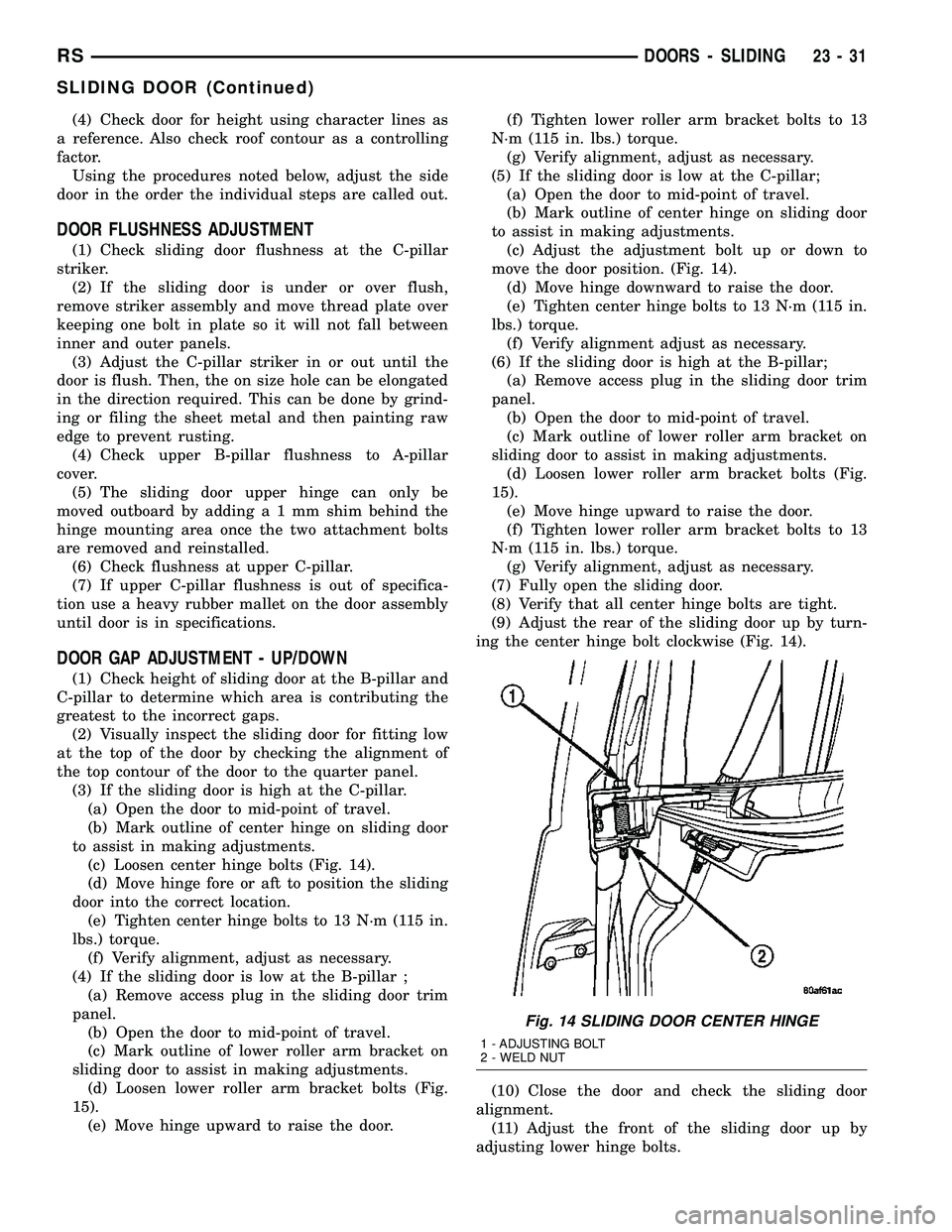
(c) Loosen center hinge bolts (Fig. 14).
(d) Move hinge fore or aft to position the sliding
door into the correct location.
(e) Tighten center hinge bolts to 13 N´m (115 in.
lbs.) torque.
(f) Verify alignment, adjust as necessary.
(4) If the sliding door is low at the B-pillar ;
(a) Remove access plug in the sliding door trim
panel.
(b) Open the door to mid-point of travel.
(c) Mark outline of lower roller arm bracket on
sliding door to assist in making adjustments.
(d) Loosen lower roller arm bracket bolts (Fig.
15).
(e) Move hinge upward to raise the door.(f) Tighten lower roller arm bracket bolts to 13
N´m (115 in. lbs.) torque.
(g) Verify alignment, adjust as necessary.
(5) If the sliding door is low at the C-pillar;
(a) Open the door to mid-point of travel.
(b) Mark outline of center hinge on sliding door
to assist in making adjustments.
(c) Adjust the adjustment bolt up or down to
move the door position. (Fig. 14).
(d) Move hinge downward to raise the door.
(e) Tighten center hinge bolts to 13 N´m (115 in.
lbs.) torque.
(f) Verify alignment adjust as necessary.
(6) If the sliding door is high at the B-pillar;
(a) Remove access plug in the sliding door trim
panel.
(b) Open the door to mid-point of travel.
(c) Mark outline of lower roller arm bracket on
sliding door to assist in making adjustments.
(d) Loosen lower roller arm bracket bolts (Fig.
15).
(e) Move hinge upward to raise the door.
(f) Tighten lower roller arm bracket bolts to 13
N´m (115 in. lbs.) torque.
(g) Verify alignment, adjust as necessary.
(7) Fully open the sliding door.
(8) Verify that all center hinge bolts are tight.
(9) Adjust the rear of the sliding door up by turn-
ing the center hinge bolt clockwise (Fig. 14).
(10) Close the door and check the sliding door
alignment.
(11) Adjust the front of the sliding door up by
adjusting lower hinge bolts.
Fig. 14 SLIDING DOOR CENTER HINGE
1 - ADJUSTING BOLT
2 - WELD NUT
RSDOORS - SLIDING23-31
SLIDING DOOR (Continued)
Page 1811 of 2339
(12) Open door half way and remove lower hinge
bolt access plug.
(13) Loosen bolts as necessary to move the front of
door up or down.
(14) Check the upper hinge for possible bind,
adjust as necessary.
(15) Close the door and check the sliding door
alignment.
(16) Fully open door and apply thread lock nut
onto the center hinge bolt. Tighten nut until till it
butts up against the welded nut on the center hinge.
Tighten nut to 13 N´m (115 in. lbs.) torque. It may be
necessary to hold the center hinge bolt to prevent it
from turning while tightening nut.
(17) Verify alignment, adjust as necessary.
DOOR GAP ADJUSTMENT - FORE/AFT
(1) Check C-pillar and B-pillar for door to aperture
gaps (5 mm + 1 mm), and door to door gap (5 mm +
1 mm).
(2) If adjust gaps require adjustment, loosen cen-
ter hinge screws as necessary to move center hinge
forward or rearward.
(3) Moving center hinge rearward increases the
gap at C-pillar and decreases gap at B-pillar. Moving
center hinge forward decreases gap at the C-pillar
and increases gap at the B-pillar
(4) Move center hinge as necessary, and tighten
screws.
(5) Close the door and check the sliding door align-
ment.
(6) Verify door alignment, adjust as necessary.
(7) Tighten center hinge screws to 13 N´m (115 in.
lbs.) torque.
DOOR SEAL COMPRESSION
(1) First check Gap & Flush (Refer to 23 - BODY/
BODY STRUCTURE/GAP AND FLUSH - SPECIFI-
CATIONS). Check seal compression near the middle
of the door even with the latch assembly. Using a
piece of paper, place it across door seal and close
door. Pull paper out of door opening. If paper tears
setting is to tight, if paper slides thought to easily
the compression is insufficient and needs to be
adjusted.
(2) Adjust seal compression at the top of the B-pil-
lar seal;
(a) Open door to mid-point of travel.
(b) Mark outline of upper roller arm on door to
assist in making adjustments.
(c) Loosen bolts attaching upper roller arm to
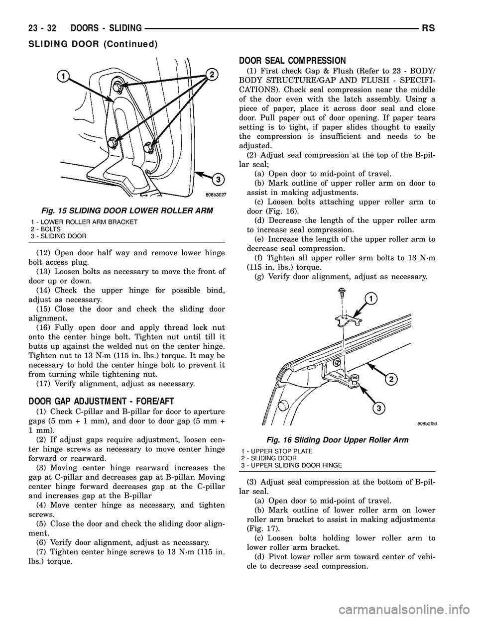
door (Fig. 16).
(d) Decrease the length of the upper roller arm
to increase seal compression.
(e) Increase the length of the upper roller arm to
decrease seal compression.
(f) Tighten all upper roller arm bolts to 13 N´m
(115 in. lbs.) torque.
(g) Verify door alignment, adjust as necessary.
(3) Adjust seal compression at the bottom of B-pil-
lar seal.
(a) Open door to mid-point of travel.
(b) Mark outline of lower roller arm on lower
roller arm bracket to assist in making adjustments
(Fig. 17).
(c) Loosen bolts holding lower roller arm to
lower roller arm bracket.
(d) Pivot lower roller arm toward center of vehi-
cle to decrease seal compression.
Fig. 15 SLIDING DOOR LOWER ROLLER ARM
1 - LOWER ROLLER ARM BRACKET
2 - BOLTS
3 - SLIDING DOOR
Fig. 16 Sliding Door Upper Roller Arm
1 - UPPER STOP PLATE
2 - SLIDING DOOR
3 - UPPER SLIDING DOOR HINGE
23 - 32 DOORS - SLIDINGRS
SLIDING DOOR (Continued)
Page 1837 of 2339
INSTALLATION
(1) Place front riser into position on luggage rack
side rail.
(2) Install two fasteners into the riser.
(3) Repeat for the opposite side, if necessary.
LUGGAGE RACK CROSSBAR
REMOVAL
(1) Remove luggage rack front risers.
(2) Depress stanchion levers down until they click
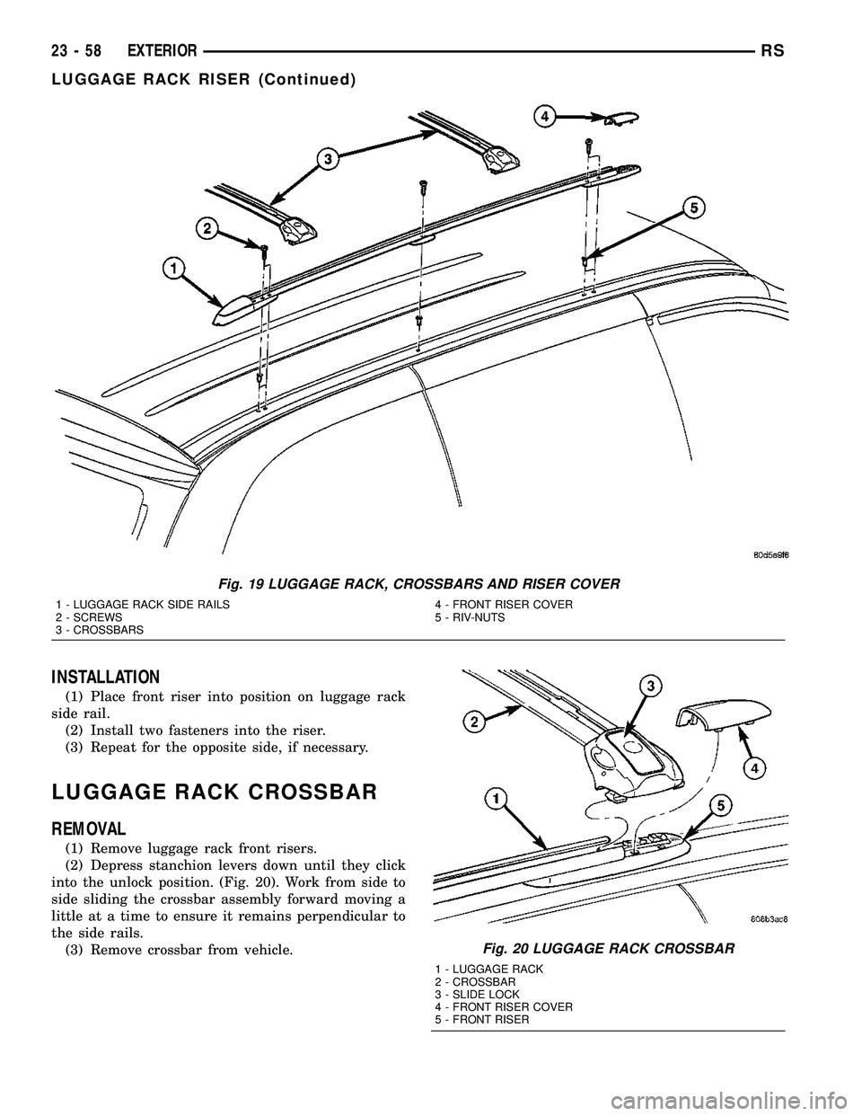
into the unlock position. (Fig. 20). Work from side to
side sliding the crossbar assembly forward moving a
little at a time to ensure it remains perpendicular to
the side rails.
(3) Remove crossbar from vehicle.
Fig. 19 LUGGAGE RACK, CROSSBARS AND RISER COVER
1 - LUGGAGE RACK SIDE RAILS
2 - SCREWS
3 - CROSSBARS4 - FRONT RISER COVER
5 - RIV-NUTS
Fig. 20 LUGGAGE RACK CROSSBAR
1 - LUGGAGE RACK
2 - CROSSBAR
3 - SLIDE LOCK
4 - FRONT RISER COVER
5 - FRONT RISER
23 - 58 EXTERIORRS
LUGGAGE RACK RISER (Continued)
Page 1859 of 2339
(1) Slide lower seat belt cover rearward to expose
anchor fastener.
(2) Remove bolt/nut attaching lower seat belt
anchor to floor.
(3) Remove upper B-pillar trim cover.
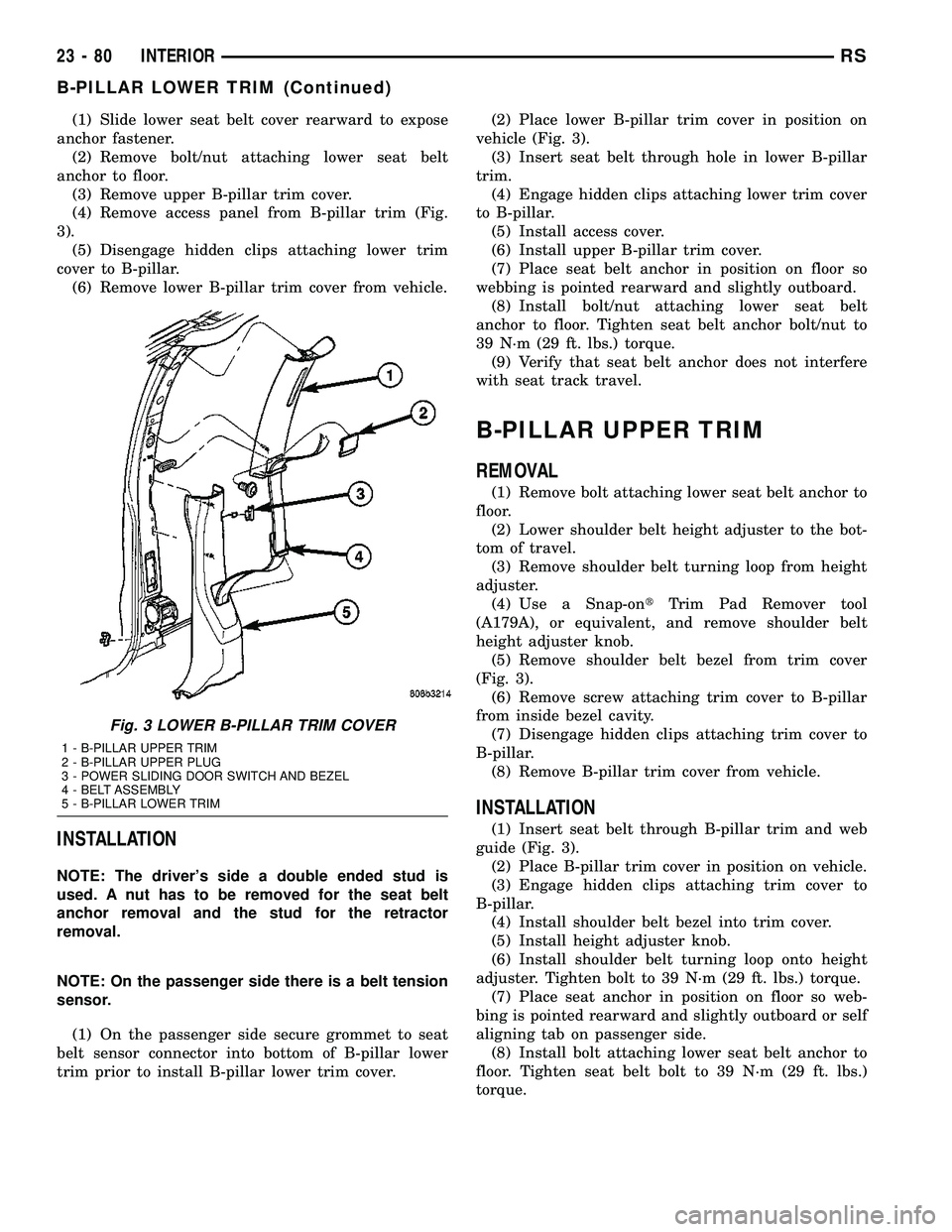
(4) Remove access panel from B-pillar trim (Fig.
3).
(5) Disengage hidden clips attaching lower trim
cover to B-pillar.
(6) Remove lower B-pillar trim cover from vehicle.
INSTALLATION
NOTE: The driver's side a double ended stud is
used. A nut has to be removed for the seat belt
anchor removal and the stud for the retractor
removal.
NOTE: On the passenger side there is a belt tension
sensor.
(1) On the passenger side secure grommet to seat
belt sensor connector into bottom of B-pillar lower
trim prior to install B-pillar lower trim cover.(2) Place lower B-pillar trim cover in position on
vehicle (Fig. 3).
(3) Insert seat belt through hole in lower B-pillar
trim.
(4) Engage hidden clips attaching lower trim cover
to B-pillar.
(5) Install access cover.
(6) Install upper B-pillar trim cover.
(7) Place seat belt anchor in position on floor so
webbing is pointed rearward and slightly outboard.
(8) Install bolt/nut attaching lower seat belt
anchor to floor. Tighten seat belt anchor bolt/nut to
39 N´m (29 ft. lbs.) torque.
(9) Verify that seat belt anchor does not interfere
with seat track travel.
B-PILLAR UPPER TRIM
REMOVAL
(1) Remove bolt attaching lower seat belt anchor to
floor.
(2) Lower shoulder belt height adjuster to the bot-
tom of travel.
(3) Remove shoulder belt turning loop from height
adjuster.
(4) Use a Snap-ontTrim Pad Remover tool
(A179A), or equivalent, and remove shoulder belt
height adjuster knob.
(5) Remove shoulder belt bezel from trim cover
(Fig. 3).
(6) Remove screw attaching trim cover to B-pillar
from inside bezel cavity.
(7) Disengage hidden clips attaching trim cover to
B-pillar.
(8) Remove B-pillar trim cover from vehicle.
INSTALLATION
(1) Insert seat belt through B-pillar trim and web
guide (Fig. 3).
(2) Place B-pillar trim cover in position on vehicle.
(3) Engage hidden clips attaching trim cover to
B-pillar.
(4) Install shoulder belt bezel into trim cover.
(5) Install height adjuster knob.
(6) Install shoulder belt turning loop onto height
adjuster. Tighten bolt to 39 N´m (29 ft. lbs.) torque.
(7) Place seat anchor in position on floor so web-
bing is pointed rearward and slightly outboard or self
aligning tab on passenger side.
(8) Install bolt attaching lower seat belt anchor to
floor. Tighten seat belt bolt to 39 N´m (29 ft. lbs.)
torque.
Fig. 3 LOWER B-PILLAR TRIM COVER
1 - B-PILLAR UPPER TRIM
2 - B-PILLAR UPPER PLUG
3 - POWER SLIDING DOOR SWITCH AND BEZEL
4 - BELT ASSEMBLY
5 - B-PILLAR LOWER TRIM
23 - 80 INTERIORRS
B-PILLAR LOWER TRIM (Continued)
Page 1861 of 2339
CARPETS - FOLD-IN-FLOOR
REMOVAL
(1) Remove floor mats.
(2) Remove front seats. (Refer to 23 - BODY/
SEATS/SEAT - REMOVAL)
(3) Remove instrument panel lower console. (Refer
to 23 - BODY/INSTRUMENT PANEL/STORAGE
BIN - REMOVAL).
(4) Remove the floor console base tray and discon-
nect wire connector from the base tray.(Refer to 23 -
BODY/INTERIOR/FLOOR CONSOLE BASE TRAY -
REMOVAL)
(5) Remove heel blocker (plastic block below accel-
erator pedal).
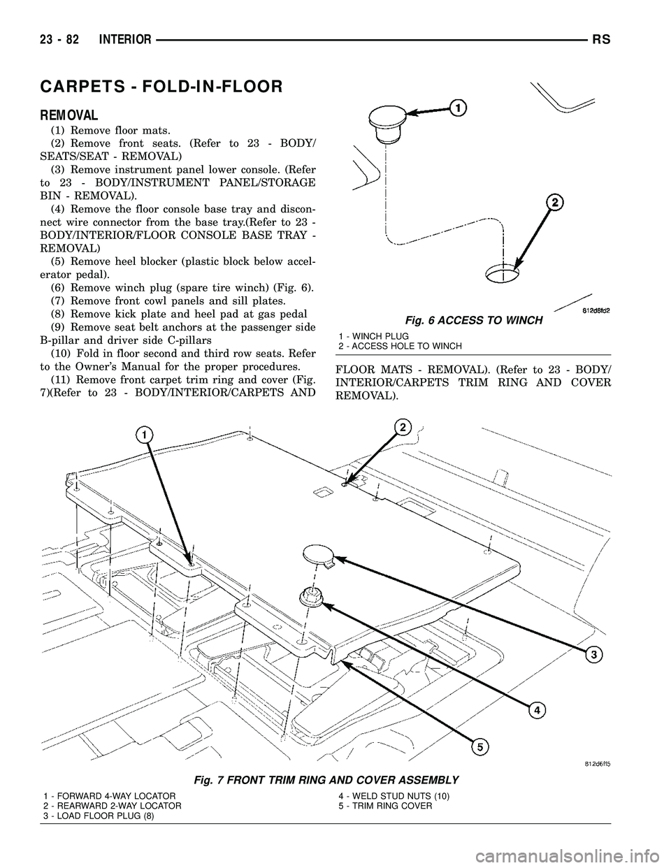
(6) Remove winch plug (spare tire winch) (Fig. 6).
(7) Remove front cowl panels and sill plates.
(8) Remove kick plate and heel pad at gas pedal
(9) Remove seat belt anchors at the passenger side
B-pillar and driver side C-pillars
(10) Fold in floor second and third row seats. Refer
to the Owner's Manual for the proper procedures.
(11) Remove front carpet trim ring and cover (Fig.
7)(Refer to 23 - BODY/INTERIOR/CARPETS ANDFLOOR MATS - REMOVAL). (Refer to 23 - BODY/
INTERIOR/CARPETS TRIM RING AND COVER
REMOVAL).
Fig. 6 ACCESS TO WINCH
1 - WINCH PLUG
2 - ACCESS HOLE TO WINCH
Fig. 7 FRONT TRIM RING AND COVER ASSEMBLY
1 - FORWARD 4-WAY LOCATOR
2 - REARWARD 2-WAY LOCATOR
3 - LOAD FLOOR PLUG (8)4 - WELD STUD NUTS (10)
5 - TRIM RING COVER
23 - 82 INTERIORRS
Page 1863 of 2339
(3) Roll carpet forward under instrument panel
(Fig. 8).
(4) Install push pins fasteners through carpet and
grommet into floor to attach carpet to floor in front
seat area.
(5) Pull wire harnesses through the carpet as
needed.
(6) Smooth out the carpet and allowing weld studs
to go all the way through the carpet.
(7) Install rear push pins fasteners attaching rear
of carpet.
(8) Place third row carpet cover into position and
press clips into position (Fig. 9).
(9) Slide the carpet under the quarter trim panel
into position.
(10) Install lower B-pillar trim covers.
(11) Install sliding door sill plates. (Refer to 23 -
BODY/INTERIOR/SLIDING DOOR SILL PLATE -
INSTALLATION).
(12) Install front carpet trim ring and cover (Fig.
7). (Refer to 23 - BODY/INTERIOR/CARPETS TRIM
RING AND COVER - INSTALLATION)
(13) Install seat belt anchors at the passenger side
B-pillar and driver side C-pillars
(14) Install kick plate and heel pad at the gas
pedal
(15) Install winch plug (spare tire winch) (Fig. 6).
(16) Install front cowl panels and sill plates.
(17) Install heel blocker (plastic block below accel-
erator pedal).
(18) Install the floor console base tray and discon-
nect wire connector from the base tray. (Refer to 23 -
BODY/INTERIOR/FLOOR CONSOLE BASE TRAY -
INSTALLATION).
(19) Install instrument panel lower console. (Refer
to 23 - BODY/INSTRUMENT PANEL/STORAGE
BIN - INSTALLATION).
(20) Install front seats. (Refer to 23 - BODY/
SEATS/SEAT - REMOVAL).
(21) Install floor mats.CARPET TRIM RING AND
COVER - FOLD-IN-FLOOR
REMOVAL
(1) Move front seats to the full forward position.
(2) Fold the second row seats into the floor.
(3) Remove the load floor plugs (Fig. 10).
(4) Remove the ten weld nuts.
(5) Open door covers (Fig. 11).
(6) Remove the four inter weld nuts (Fig. 12).
(7) Raise the front trim ring and cover up off of
the weld studs and remove from vehicle.
INSTALLATION
(1) Place front trim ring and cover assembly into
position.
(2) Open door covers (Fig. 11).
(3) Install the four inter weld nuts (Fig. 12).
(4) Close door covers.
(5) Install the ten weld nuts (Fig. 10).
(6) Install the eight load floor plugs.
(7) Open the second row seats into position.
(8) Move front seats to the position.
23 - 84 INTERIORRS
CARPETS - FOLD-IN-FLOOR (Continued)
Page 1864 of 2339
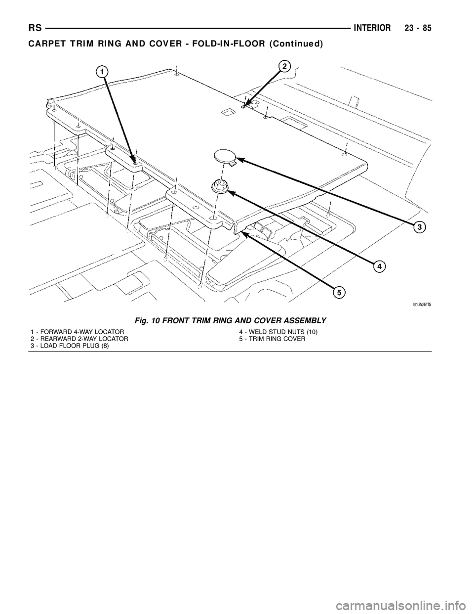
Fig. 10 FRONT TRIM RING AND COVER ASSEMBLY
1 - FORWARD 4-WAY LOCATOR
2 - REARWARD 2-WAY LOCATOR
3 - LOAD FLOOR PLUG (8)4 - WELD STUD NUTS (10)
5 - TRIM RING COVER
RSINTERIOR23-85
CARPET TRIM RING AND COVER - FOLD-IN-FLOOR (Continued)
Page 1888 of 2339
If any of the remaining OCS components of the
passenger side front seat cushion require replace-
ment, they are serviced only as a factory-calibrated,
assembled, and tamper-evident service replacement
package. This package includes the assembled frame,
springs, pad, bladder, sensor, foam, wiring and a cal-
ibrated OCM. When installing this package, always
replace all of the existing components with the new
components as a unit. Do not attempt to separate or
disconnect any of the new OCS components con-
tained in the service replacement package from each
other, and do not attempt to reuse any of the
replaced components in this or any other vehicle.
Once any of the original factory-installed compo-
nents except the OCM have been replaced with the
service replacement package components, the OCM
can only be serviced by replacing the entire passen-
ger side front seat cushion unit with another com-
plete service replacement package. (Refer to 23 -
BODY/SEATS/SEAT CUSHION - FRONT -
REMOVAL).
WARNING: TO AVOID PERSONAL INJURY OR
DEATH, ON VEHICLES EQUIPPED WITH AIRBAGS,
DISABLE THE SUPPLEMENTAL RESTRAINT SYS-
TEM BEFORE ATTEMPTING ANY STEERING
WHEEL, STEERING COLUMN, AIRBAG, OCCUPANT
CLASSIFICATION SYSTEM, SEAT BELT TEN-
SIONER, IMPACT SENSOR, OR INSTRUMENT
PANEL COMPONENT DIAGNOSIS OR SERVICE.
DISCONNECT AND ISOLATE THE BATTERY NEGA-
TIVE (GROUND) CABLE, THEN WAIT TWO MINUTES
FOR THE SYSTEM CAPACITOR TO DISCHARGE
BEFORE PERFORMING FURTHER DIAGNOSIS OR
SERVICE. THIS IS THE ONLY SURE WAY TO DIS-
ABLE THE SUPPLEMENTAL RESTRAINT SYSTEM.
FAILURE TO TAKE THE PROPER PRECAUTIONS
COULD RESULT IN ACCIDENTAL AIRBAG DEPLOY-
MENT.
WARNING: TO AVOID PERSONAL INJURY OR
DEATH ON VEHICLES EQUIPPED WITH THE OCCU-
PANT CLASSIFICATION SYSTEM (OCS), ONLY THE
OCCUPANT CLASSIFICATION MODULE (OCM) AND
THE SEAT CUSHION TRIM MAY BE SERVICED SEP-
ARATELY. ALL OTHER COMPONENTS OF THE PAS-
SENGER SIDE FRONT SEAT CUSHION ASSEMBLY
MUST BE SERVICED ONLY AS A COMPLETE FAC-
TORY-CALIBRATED, ASSEMBLED AND TAMPER-EV-
IDENT SERVICE REPLACEMENT PACKAGE. THIS
PACKAGE INCLUDES THE FRAME, SPRINGS, PAD,
BLADDER, SENSOR, FOAM, WIRING AND A CALI-
BRATED OCM. WHEN INSTALLING THIS PACKAGE
ALWAYS REPLACE ALL OF THE EXISTING COMPO-
NENTS WITH THE NEW COMPONENTS AS A UNIT.
DO NOT ATTEMPT TO SEPARATE OR DISCONNECTANY OF THE NEW OCS COMPONENTS IN THE SER-
VICE REPLACEMENT PACKAGE FROM EACH
OTHER, AND DO NOT ATTEMPT TO REUSE ANY OF
THE REPLACED COMPONENTS IN THIS OR ANY
OTHER VEHICLE. FAILURE TO TAKE THE PROPER
PRECAUTIONS COULD RESULT IN FAILURE OF
THE PASSENGER AIRBAG TO DEPLOY WHEN
REQUIRED, OR IN PASSENGER AIRBAG DEPLOY-
MENT WHEN NOT REQUIRED.
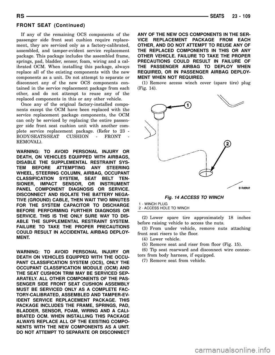
(1) Remove access winch cover (spare tire) plug
(Fig. 14).
(2) Lower spare tire approximately 18 inches
before raising vehicle to access the nuts.
(3) From under vehicle, remove nuts attaching
front seat risers to the floor.
(4) Lower vehicle.
(5) Remove seat and riser from floor (Fig. 15).
(6) Tip seat rearward and disconnect wire connec-
tors from body harness, if equipped.
(7) Remove seat from vehicle.
Fig. 14 ACCESS TO WINCH
1 - WINCH PLUG
2 - ACCESS HOLE TO WINCH
RSSEATS23 - 109
FRONT SEAT (Continued)