Page 1779 of 2339

(8) Road test vehicle to ensure proper operation of
the brakes.
WHEEL MOUNTING STUDS -
REAR
REMOVAL
CAUTION: If a wheel attaching stud needs to be
replaced in the hub and bearing assembly the studs
MUST NOT be hammered out of the hub flange. If a
stud is removed by hammering it out of the bearing
flange, damage to the hub and bearing assembly
will occur leading to premature hub and bearing
failure.
(1) Raise vehicle on jackstands or centered on a
frame contact type hoist. See Hoisting in Lubrication
and Maintenance.
(2) Remove the rear wheel and tire assembly.
(3) Remove the brake drum or disc brake caliper
and rotor. Refer to Brakes.
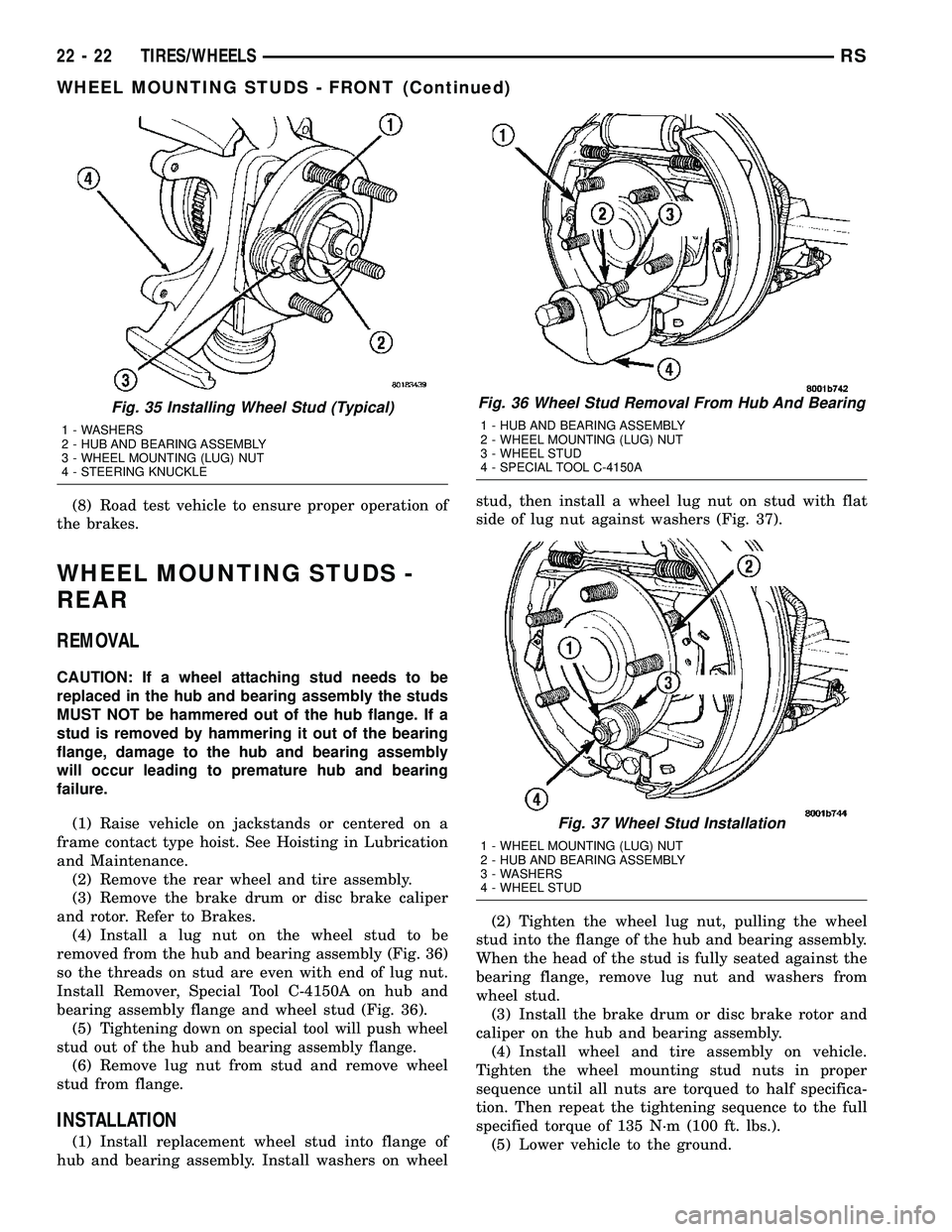
(4) Install a lug nut on the wheel stud to be
removed from the hub and bearing assembly (Fig. 36)
so the threads on stud are even with end of lug nut.
Install Remover, Special Tool C-4150A on hub and
bearing assembly flange and wheel stud (Fig. 36).
(5)
Tightening down on special tool will push wheel
stud out of the hub and bearing assembly flange.
(6) Remove lug nut from stud and remove wheel
stud from flange.
INSTALLATION
(1) Install replacement wheel stud into flange of
hub and bearing assembly. Install washers on wheelstud, then install a wheel lug nut on stud with flat
side of lug nut against washers (Fig. 37).
(2) Tighten the wheel lug nut, pulling the wheel
stud into the flange of the hub and bearing assembly.
When the head of the stud is fully seated against the
bearing flange, remove lug nut and washers from
wheel stud.
(3) Install the brake drum or disc brake rotor and
caliper on the hub and bearing assembly.
(4) Install wheel and tire assembly on vehicle.
Tighten the wheel mounting stud nuts in proper
sequence until all nuts are torqued to half specifica-
tion. Then repeat the tightening sequence to the full
specified torque of 135 N´m (100 ft. lbs.).
(5) Lower vehicle to the ground.
Fig. 35 Installing Wheel Stud (Typical)
1 - WASHERS
2 - HUB AND BEARING ASSEMBLY
3 - WHEEL MOUNTING (LUG) NUT
4 - STEERING KNUCKLE
Fig. 36 Wheel Stud Removal From Hub And Bearing
1 - HUB AND BEARING ASSEMBLY
2 - WHEEL MOUNTING (LUG) NUT
3 - WHEEL STUD
4 - SPECIAL TOOL C-4150A
Fig. 37 Wheel Stud Installation
1 - WHEEL MOUNTING (LUG) NUT
2 - HUB AND BEARING ASSEMBLY
3 - WASHERS
4 - WHEEL STUD
22 - 22 TIRES/WHEELSRS
WHEEL MOUNTING STUDS - FRONT (Continued)
Page 1788 of 2339

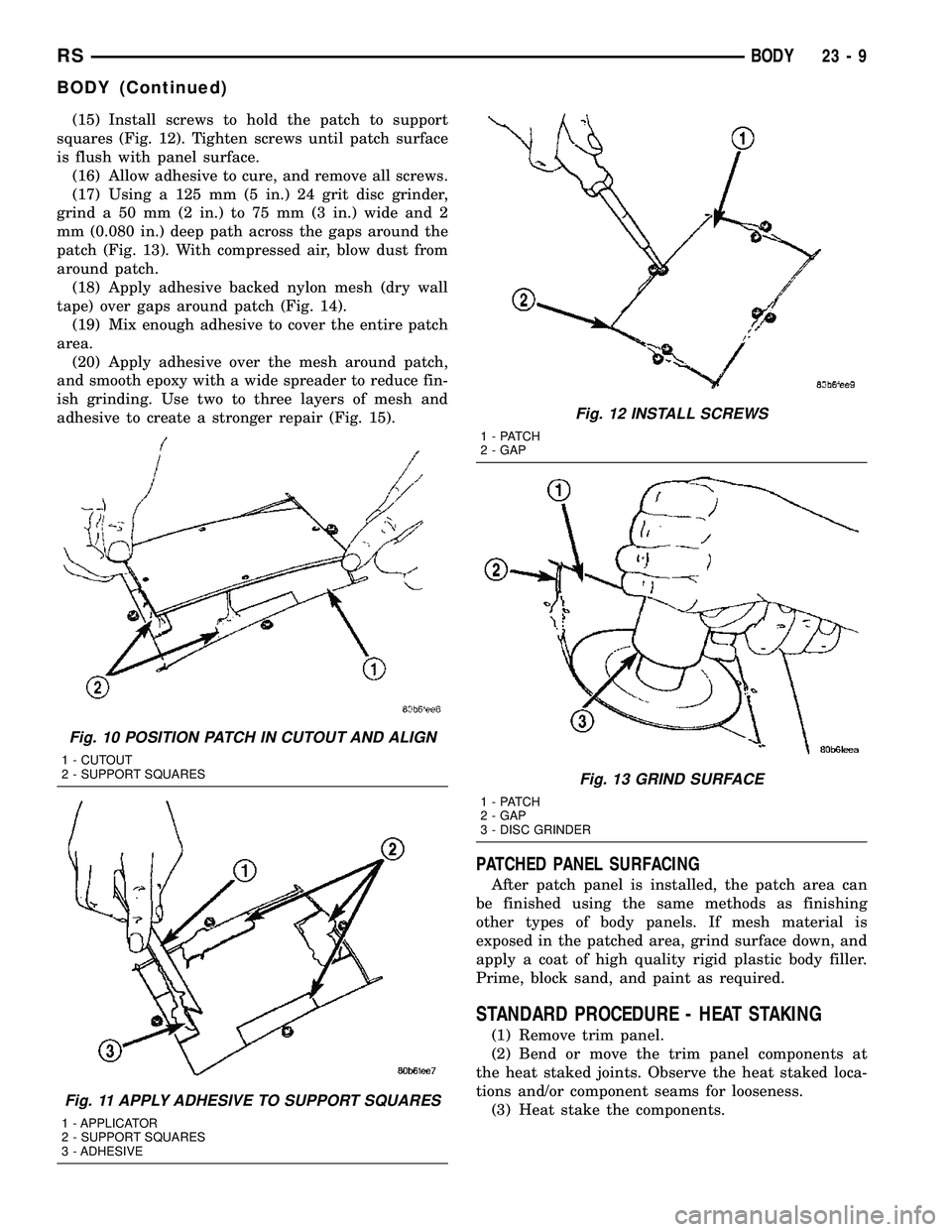
(15) Install screws to hold the patch to support
squares (Fig. 12). Tighten screws until patch surface
is flush with panel surface.
(16) Allow adhesive to cure, and remove all screws.
(17) Using a 125 mm (5 in.) 24 grit disc grinder,
grind a 50 mm (2 in.) to 75 mm (3 in.) wide and 2
mm (0.080 in.) deep path across the gaps around the
patch (Fig. 13). With compressed air, blow dust from
around patch.
(18) Apply adhesive backed nylon mesh (dry wall
tape) over gaps around patch (Fig. 14).
(19) Mix enough adhesive to cover the entire patch
area.
(20) Apply adhesive over the mesh around patch,
and smooth epoxy with a wide spreader to reduce fin-
ish grinding. Use two to three layers of mesh and
adhesive to create a stronger repair (Fig. 15).
PATCHED PANEL SURFACING
After patch panel is installed, the patch area can
be finished using the same methods as finishing
other types of body panels. If mesh material is
exposed in the patched area, grind surface down, and
apply a coat of high quality rigid plastic body filler.
Prime, block sand, and paint as required.
STANDARD PROCEDURE - HEAT STAKING
(1) Remove trim panel.
(2) Bend or move the trim panel components at
the heat staked joints. Observe the heat staked loca-
tions and/or component seams for looseness.
(3) Heat stake the components.
Fig. 10 POSITION PATCH IN CUTOUT AND ALIGN
1 - CUTOUT
2 - SUPPORT SQUARES
Fig. 11 APPLY ADHESIVE TO SUPPORT SQUARES
1 - APPLICATOR
2 - SUPPORT SQUARES
3 - ADHESIVE
Fig. 12 INSTALL SCREWS
1 - PATCH
2 - GAP
Fig. 13 GRIND SURFACE
1 - PATCH
2 - GAP
3 - DISC GRINDER
RSBODY23-9
BODY (Continued)
Page 2216 of 2339

PLUMBING - FRONT
DESCRIPTION
CAUTION: The system must be completely empty
before opening any fitting or connection in the
refrigeration system. Open fittings with caution
even after the system has been emptied. If any
pressure is noticed as a fitting is loosened,
retighten fitting and evacuate the system again.
The use of correct wrenches when making connec-
tions is very important. Improper wrenches or
improper use of wrenches can damage the fittings.
The internal parts of the A/C system will remain sta-
ble as long as moisture-free refrigerant and refrig-
erant oil is used. Abnormal amounts of dirt,
moisture or air can upset the chemical stability.
This may cause operational troubles or even seri-
ous damage if present in more than very small
quantities. Before disconnecting a refrigerant line
or hose, clean the outside of the fittings thoroughly
to prevent contamination from entering the refriger-
ant system.
When opening a refrigeration system, have every-
thing you will need to repair the system ready to
minimize the amount of time the system is opened.
Cap or plug all refrigerant line fittings as soon as
they are opened. This will help prevent the entrance
of dirt and moisture. All new lines and components
should be capped or sealed until they are ready to
be used. Before connecting a refrigerant line or
hose, clean the outside of the fittings thoroughly to
prevent contamination from entering the refrigerant
system.
All tools, including the refrigerant dispensing mani-
fold, manifold gauge set and test hoses should be
kept clean and dry.
The A/C refrigerant lines and hoses are used to
carry the refrigerant between the various A/C system
components. The refrigerant lines and hoses for the
R-134a system on this vehicle consist of a barrier-
hose design with a nylon tube sandwiched between
rubber layers. The nylon tube helps to contain the
R-134a refrigerant, which has a smaller molecular
structure than R-12 refrigerant. The ends of the
refrigerant lines are made from lightweight alumi-
num or steel, and commonly use braze-less fittings.Any kinks or sharp bends in the refrigerant lines
and hoses will reduce the capacity of the entire A/C
system and can reduce the flow of refrigerant in the
system. The radius of all bends in the flexible hose
refrigerant lines should be at least ten times the
diameter of the hose and the refrigerant lines should
be routed so they are at least 80 millimeters (3
inches) away from the exhaust manifold(s) and
exhaust pipe(s).
OPERATION
High pressures are produced in the refrigerant sys-
tem when the A/C compressor is operating. Extreme
care must be exercised to make sure that each of the
refrigerant system connections is pressure-tight and
leak free. It is a good practice to inspect all flexible
hose refrigerant lines at least once a year to make
sure they are in good condition and properly routed.
The refrigerant lines and hoses are coupled to
other A/C system components with block-type fit-
tings. An O-ring seal, or a flat steel gasket with an
integral O-ring (dual plane seal), is used to mate the
refrigerant line fittings with A/C system components
to ensure the integrity of the refrigerant system.
The refrigerant lines and hoses cannot be repaired
and, if faulty or damaged, they must be replaced.
WARNING
ENGINE COOLING SYSTEM
WARNING: THE ENGINE COOLING SYSTEM IS
DESIGNED TO DEVELOP INTERNAL PRESSURES
OF 97 TO 123 KILOPASCALS (14 TO 18 POUNDS
PER SQUARE INCH). DO NOT REMOVE OR
LOOSEN THE COOLANT PRESSURE CAP, CYLIN-
DER BLOCK DRAIN PLUGS, RADIATOR DRAIN,
RADIATOR HOSES, HEATER HOSES, OR HOSE
CLAMPS WHILE THE ENGINE COOLING SYSTEM IS
HOT AND UNDER PRESSURE. FAILURE TO
OBSERVE THIS WARNING CAN RESULT IN SERI-
OUS BURNS FROM THE HEATED ENGINE COOL-
ANT. ALLOW THE VEHICLE TO COOL FOR A
MINIMUM OF 15 MINUTES BEFORE OPENING THE
COOLING SYSTEM FOR SERVICE.
RSPLUMBING - FRONT24-65