2005 CHRYSLER VOYAGER torque
[x] Cancel search: torquePage 1911 of 2339
SEAT - SECOND ROW -
FOLD-IN-FLOOR
REMOVAL
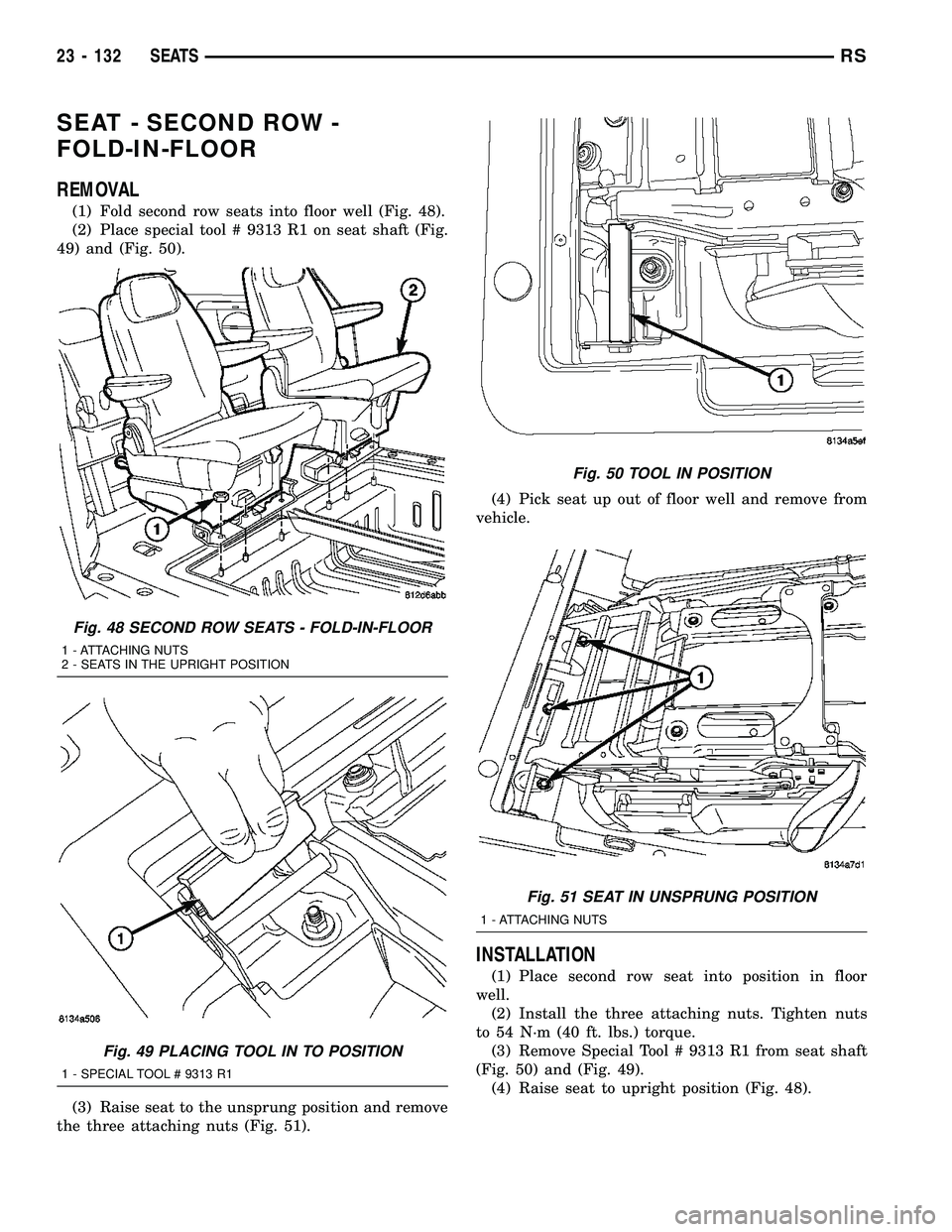
(1) Fold second row seats into floor well (Fig. 48).
(2) Place special tool # 9313 R1 on seat shaft (Fig.
49) and (Fig. 50).
(3) Raise seat to the unsprung position and remove
the three attaching nuts (Fig. 51).(4) Pick seat up out of floor well and remove from
vehicle.
INSTALLATION
(1) Place second row seat into position in floor
well.
(2) Install the three attaching nuts. Tighten nuts
to 54 N´m (40 ft. lbs.) torque.
(3) Remove Special Tool # 9313 R1 from seat shaft
(Fig. 50) and (Fig. 49).
(4) Raise seat to upright position (Fig. 48).
Fig. 48 SECOND ROW SEATS - FOLD-IN-FLOOR
1 - ATTACHING NUTS
2 - SEATS IN THE UPRIGHT POSITION
Fig. 49 PLACING TOOL IN TO POSITION
1 - SPECIAL TOOL # 9313 R1
Fig. 50 TOOL IN POSITION
Fig. 51 SEAT IN UNSPRUNG POSITION
1 - ATTACHING NUTS
23 - 132 SEATSRS
Page 1920 of 2339
INSTALLATION
(1) Install the seat back.
(2) Install the shoulder bolts attaching the seat
back hinge to the seat back frame and tighten to 48
N´m (35 ft. lbs.) torque.
(3) Connect the child seat synchronizer cable, if
equipped.
(4) Install the seat back hinge covers. (Refer to 23
- BODY/SEATS/SEAT BACK HINGE COVERS -
QUAD BUCKET, 50/50 SPLIT, BENCH - INSTALLA-
TION)
(5) Install the armrests. (Refer to 23 - BODY/
SEATS/ARMREST - INSTALLATION)
(6) Install the headrest. (Refer to 23 - BODY/
SEATS/HEADREST - INSTALLATION)
(7) Verify seat back operation.
QUAD SEAT CUSHION
REMOVAL
(1) Remove the quad bucket seat side shields and
cup holder. (Refer to 23 - BODY/SEATS/SEAT SIDE
SHIELD/QUAD BUCKET SEAT SIDE SHIELD/CUP
HOLDER - REMOVAL) and (Refer to 23 - BODY/
SEATS/QUAD BUCKET SEAT SIDE SHIELD - NO
CUP HOLDER - REMOVAL)
(2) Remove seat track front and rear covers if
equipped. (Refer to 23 - BODY/SEATS/SEAT TRACK
REAR COVER - REMOVAL) and (Refer to 23 -
BODY/SEATS/SEAT TRACK FRONT COVER -
REMOVAL)(3) If equipped, open storage bin to access front
pan bolts.
(4) Remove bolts attaching seat cushion pan to
seat riser.
(5) Disconnect wire connectors, if equipment.
(6) Remove seat cushion from seat.
(7) Disengage J-strap retainers holding seat cover
to cushion.
(8) Remove seat cushion pan from cover and pad.
INSTALLATION
(1) Place seat cushion cover in position on seat
cushion.
(2) Engage J-strap retainers to hold seat cover to
cushion.
(3) Place seat cushion in position on seat.
(4) Connect wire connectors, if equipment.
(5) Install bolts attaching seat cushion to seat
riser. Tighten bolts to 40 N´m (29.5 ft. lbs.) torque.
(6) If equipped, close storage bin.
(7) Install seat track front and rear covers, if
equipped. (Refer to 23 - BODY/SEATS/SEAT TRACK
REAR COVER - INSTALLATION) and (Refer to 23 -
BODY/SEATS/SEAT TRACK FRONT COVER -
INSTALLATION)
(8) Install the quad seat side shield and cup holder
if equipped. (Refer to 23 - BODY/SEATS/QUAD
BUCKET SEAT SIDE SHIELD/CUP HOLDER -
INSTALLATION) and (Refer to 23 - BODY/SEATS/
QUAD BUCKET SEAT SIDE SHIELD - NO CUP
HOLDER - INSTALLATION)
(9) Install seat cushion side covers. (Refer to 23 -
BODY/SEATS/FRONT SEAT CUSHION SIDE
COVER - INSTALLATION)
QUAD BUCKET SEAT SIDE
SHIELD/CUP HOLDER
REMOVAL
(1) Remove the seat from the vehicle. Refer to
Owner's Manual for proper procedures.
(2) Remove the two screws and remove the hinge
cover (Fig. 81)
(3) Remove the dump latch handle.
(4) Remove the three screws (Fig. 82).
(5) Depress the tab on the cup holder assembly
(Fig. 83).
(6) Using a deep well socket or equivalent, depress
the push pin tabs and remove the cup holder assem-
bly (Fig. 84).
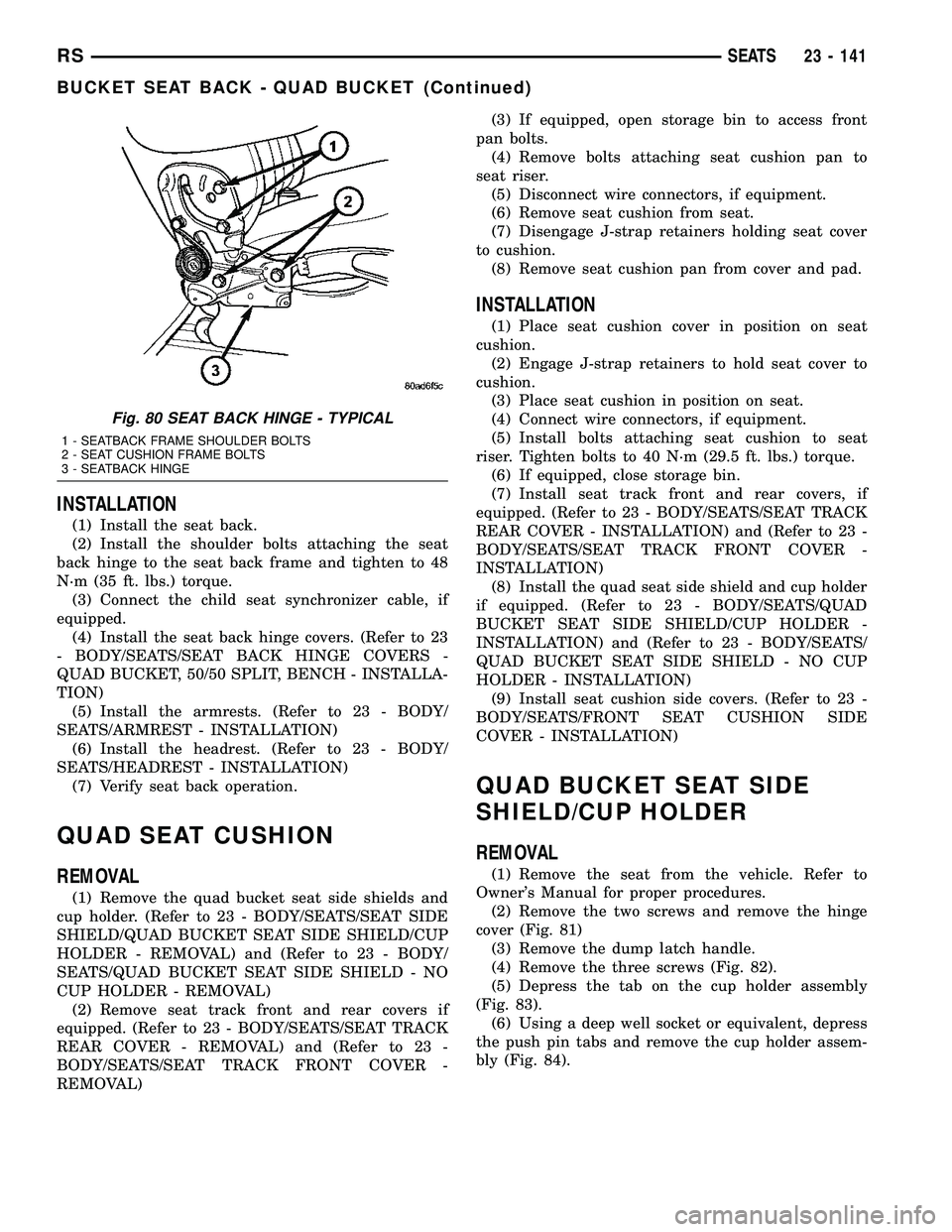
Fig. 80 SEAT BACK HINGE - TYPICAL
1 - SEATBACK FRAME SHOULDER BOLTS
2 - SEAT CUSHION FRAME BOLTS
3 - SEATBACK HINGE
RSSEATS23 - 141
BUCKET SEAT BACK - QUAD BUCKET (Continued)
Page 1924 of 2339

BENCH SEAT RISER - 50/50
SPLIT
REMOVAL
(1) Remove the seat from the vehicle. Refer to the
Owners Manual for proper procedures.
(2) Unclip the seat cushion cover J-strap. (Fig. 89).
(3) Remove the six bolts and remove the riser.
INSTALLATION
(1) Place the riser onto the seat install the bolts
and tighten to 48 N´m (35 ft. lbs.) torque.
(2) Clip seat cushion cover J-strap onto the riser.
(3) Install the seat into the vehicle. Refer to the
Owner's Manual for proper procedure.
BENCH SEAT RISER - SECOND
ROW
REMOVAL
(1) Remove seat from vehicle. Refer to Owner's
Manual for proper procedures.
(2) Place seat bottom side up on a clean covered
work surface.
(3) Remove bolts attaching seat riser to seat cush-
ion frame (Fig. 90).
(4) Remove riser from seat.
INSTALLATION
(1) Place riser in position on seat.
(2) Install bolts attaching seat riser to seat cush-
ion frame (Fig. 90). Tighten bolts to 48 N´m (35 ft.
lbs.) torque.
(3) Install seat into vehicle.
BENCH SEAT RISER - THIRD
ROW
REMOVAL
(1) Remove seat track. (Refer to 23 - BODY/
SEATS/BENCH SEAT TRACK - REMOVAL)
(2) Remove bolts attaching riser to seat cushion
frame and remove the riser. (Fig. 95).
INSTALLATION
(1) Place riser in position on seat.
(2) Install bolts attaching riser to seat cushion
frame (Fig. 95). Tighten bolts to 48 N´m (35 ft. lbs.)
torque.
(3) Install seat track. (Refer to 23 - BODY/SEATS/
BENCH SEAT TRACK - INSTALLATION)
Fig. 89 BENCH SEAT RISER - 50/50 SPLIT
1 - SEAT CUSHION COVER CLIP
2 - SEAT RISER BOLTS
3 - SEAT RISER
Fig. 90 BENCH SEAT RISER - SECOND ROW
1 - RISER
2 - FIRST ROW BENCH SEAT
3 - RISER BOLTS
RSSEATS23 - 145
Page 1925 of 2339
SEAT BACK HINGE COVERS -
QUAD BUCKET, 50/50 SPLIT,
BENCH
REMOVAL
(1) Remove seat from vehicle. Refer to Owner's
Manual for proper procedures.
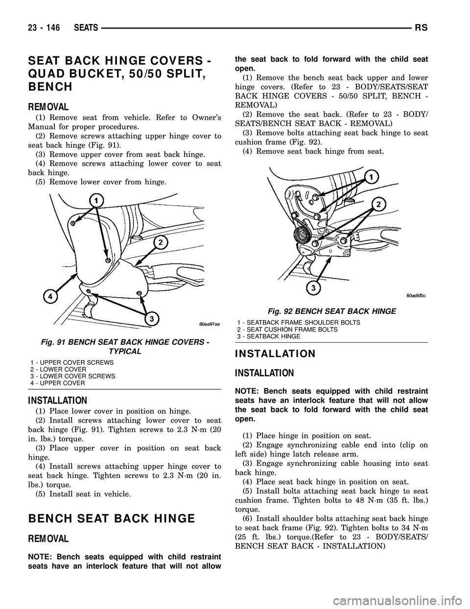
(2) Remove screws attaching upper hinge cover to
seat back hinge (Fig. 91).
(3) Remove upper cover from seat back hinge.
(4) Remove screws attaching lower cover to seat
back hinge.
(5) Remove lower cover from hinge.
INSTALLATION
(1) Place lower cover in position on hinge.
(2) Install screws attaching lower cover to seat
back hinge (Fig. 91). Tighten screws to 2.3 N´m (20
in. lbs.) torque.
(3) Place upper cover in position on seat back
hinge.
(4) Install screws attaching upper hinge cover to
seat back hinge. Tighten screws to 2.3 N´m (20 in.
lbs.) torque.
(5) Install seat in vehicle.
BENCH SEAT BACK HINGE
REMOVAL
NOTE: Bench seats equipped with child restraint
seats have an interlock feature that will not allowthe seat back to fold forward with the child seat
open.
(1) Remove the bench seat back upper and lower
hinge covers. (Refer to 23 - BODY/SEATS/SEAT
BACK HINGE COVERS - 50/50 SPLIT, BENCH -
REMOVAL)
(2) Remove the seat back. (Refer to 23 - BODY/
SEATS/BENCH SEAT BACK - REMOVAL)
(3) Remove bolts attaching seat back hinge to seat
cushion frame (Fig. 92).
(4) Remove seat back hinge from seat.
INSTALLATION
INSTALLATION
NOTE: Bench seats equipped with child restraint
seats have an interlock feature that will not allow
the seat back to fold forward with the child seat
open.
(1) Place hinge in position on seat.
(2) Engage synchronizing cable end into (clip on
left side) hinge latch release arm.
(3) Engage synchronizing cable housing into seat
back hinge.
(4) Place seat back hinge in position on seat.
(5) Install bolts attaching seat back hinge to seat
cushion frame. Tighten bolts to 48 N´m (35 ft. lbs.)
torque.
(6) Install shoulder bolts attaching seat back hinge
to seat back frame (Fig. 92). Tighten bolts to 34 N´m
(25 ft. lbs.) torque.(Refer to 23 - BODY/SEATS/
BENCH SEAT BACK - INSTALLATION)
Fig. 91 BENCH SEAT BACK HINGE COVERS -
TYPICAL
1 - UPPER COVER SCREWS
2 - LOWER COVER
3 - LOWER COVER SCREWS
4 - UPPER COVER
Fig. 92 BENCH SEAT BACK HINGE
1 - SEATBACK FRAME SHOULDER BOLTS
2 - SEAT CUSHION FRAME BOLTS
3 - SEATBACK HINGE
23 - 146 SEATSRS
Page 1927 of 2339
(1) Install the seat back.
(2) Install the shoulder bolts attaching the seat
back hinge to the seat back frame and tighten to 34
N´m (25 ft. lbs.) torque.
(3) Connect the synchronizing cable end from (clip
on left side) hinge latch release arm, if equipped.
(4) Connect the synchronizing cable housing to the
seat back hinge, if equipped.
(5) Install the upper hinge cover. (Refer to 23 -
BODY/SEATS/SEAT BACK HINGE - INSTALLA-
TION)
(6) Install the armrests, if equipped. (Refer to 23 -
BODY/SEATS/ARMREST - INSTALLATION)
(7) Install the headrest sleeves. (Refer to 23 -
BODY/SEATS/HEADREST SLEEVE - INSTALLA-
TION)
(8) Adjust synchronizing cable, if equipped. (Refer
to 23 - BODY/SEATS/SYNCHRONIZING CABLE
ADJUSTMENT)
BENCH SEAT BACK COVER
REMOVAL
(1) Remove the bench seat back. (Refer to 23 -
BODY/SEATS/BENCH SEAT BACK - REMOVAL)
(2) Remove the bench seat back panel. (Refer to 23
- BODY/SEATS/BENCH SEAT BACK PANEL -
REMOVAL)
(3) Disconnect the cover J-straps.
(4) Remove the seat back cover from the seat back
assembly.
INSTALLATION
(1) Install seat back cover onto the seat back
frame and cushion assembly.
(2) Connect the J-straps.
(3) Install the bench seat back panel. (Refer to 23 -
BODY/SEATS/BENCH SEAT BACK PANEL -
INSTALLATION)
(4) Install the seat back. (Refer to 23 - BODY/
SEATS/BENCH SEAT BACK - INSTALLATION)
BENCH SEAT TRACK
REMOVAL
(1) Remove second row seat from vehicle. Refer to
Owner's Manual for proper procedure.
(2) Place seat on clean covered work surface.
(3) Disengage seat track adjuster link wire from
track being removed.
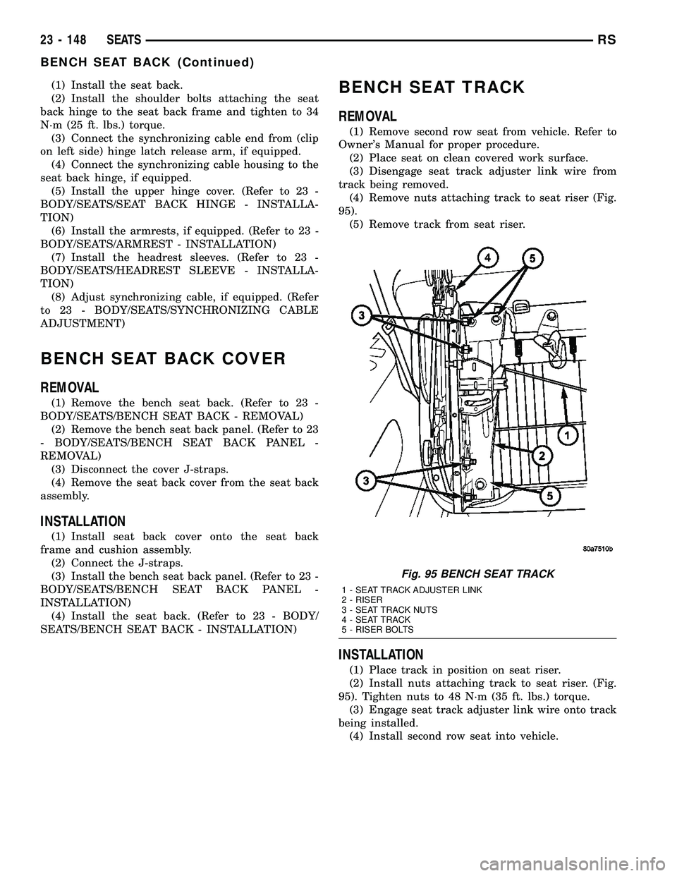
(4) Remove nuts attaching track to seat riser (Fig.
95).
(5) Remove track from seat riser.
INSTALLATION
(1) Place track in position on seat riser.
(2) Install nuts attaching track to seat riser. (Fig.
95). Tighten nuts to 48 N´m (35 ft. lbs.) torque.
(3) Engage seat track adjuster link wire onto track
being installed.
(4) Install second row seat into vehicle.
Fig. 95 BENCH SEAT TRACK
1 - SEAT TRACK ADJUSTER LINK
2 - RISER
3 - SEAT TRACK NUTS
4 - SEAT TRACK
5 - RISER BOLTS
23 - 148 SEATSRS
BENCH SEAT BACK (Continued)
Page 1928 of 2339
PLASTIC GROCERY BAG
RETAINER
REMOVAL
3-PASS BENCH SEAT
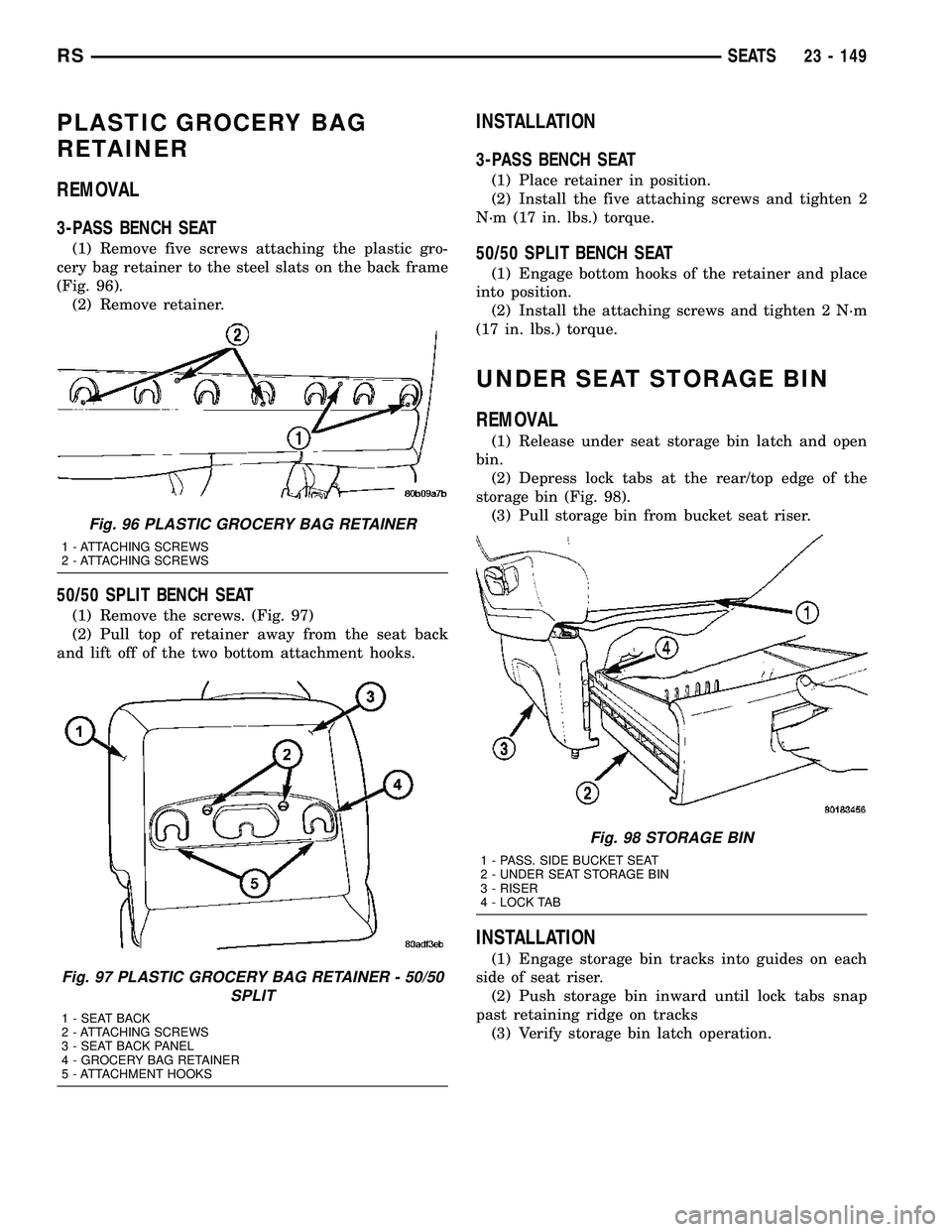
(1) Remove five screws attaching the plastic gro-
cery bag retainer to the steel slats on the back frame
(Fig. 96).
(2) Remove retainer.
50/50 SPLIT BENCH SEAT
(1) Remove the screws. (Fig. 97)
(2) Pull top of retainer away from the seat back
and lift off of the two bottom attachment hooks.
INSTALLATION
3-PASS BENCH SEAT
(1) Place retainer in position.
(2) Install the five attaching screws and tighten 2
N´m (17 in. lbs.) torque.
50/50 SPLIT BENCH SEAT
(1) Engage bottom hooks of the retainer and place
into position.
(2) Install the attaching screws and tighten 2 N´m
(17 in. lbs.) torque.
UNDER SEAT STORAGE BIN
REMOVAL
(1) Release under seat storage bin latch and open
bin.
(2) Depress lock tabs at the rear/top edge of the
storage bin (Fig. 98).
(3) Pull storage bin from bucket seat riser.
INSTALLATION
(1) Engage storage bin tracks into guides on each
side of seat riser.
(2) Push storage bin inward until lock tabs snap
past retaining ridge on tracks
(3) Verify storage bin latch operation.
Fig. 96 PLASTIC GROCERY BAG RETAINER
1 - ATTACHING SCREWS
2 - ATTACHING SCREWS
Fig. 97 PLASTIC GROCERY BAG RETAINER - 50/50
SPLIT
1 - SEAT BACK
2 - ATTACHING SCREWS
3 - SEAT BACK PANEL
4 - GROCERY BAG RETAINER
5 - ATTACHMENT HOOKS
Fig. 98 STORAGE BIN
1 - PASS. SIDE BUCKET SEAT
2 - UNDER SEAT STORAGE BIN
3 - RISER
4 - LOCK TAB
RSSEATS23 - 149
Page 1929 of 2339
UNDER SEAT STORAGE BIN
GUIDE
REMOVAL
(1) Remove under seat storage bin. (Refer to 23 -
BODY/SEATS/UNDER SEAT STORAGE BIN -
REMOVAL)
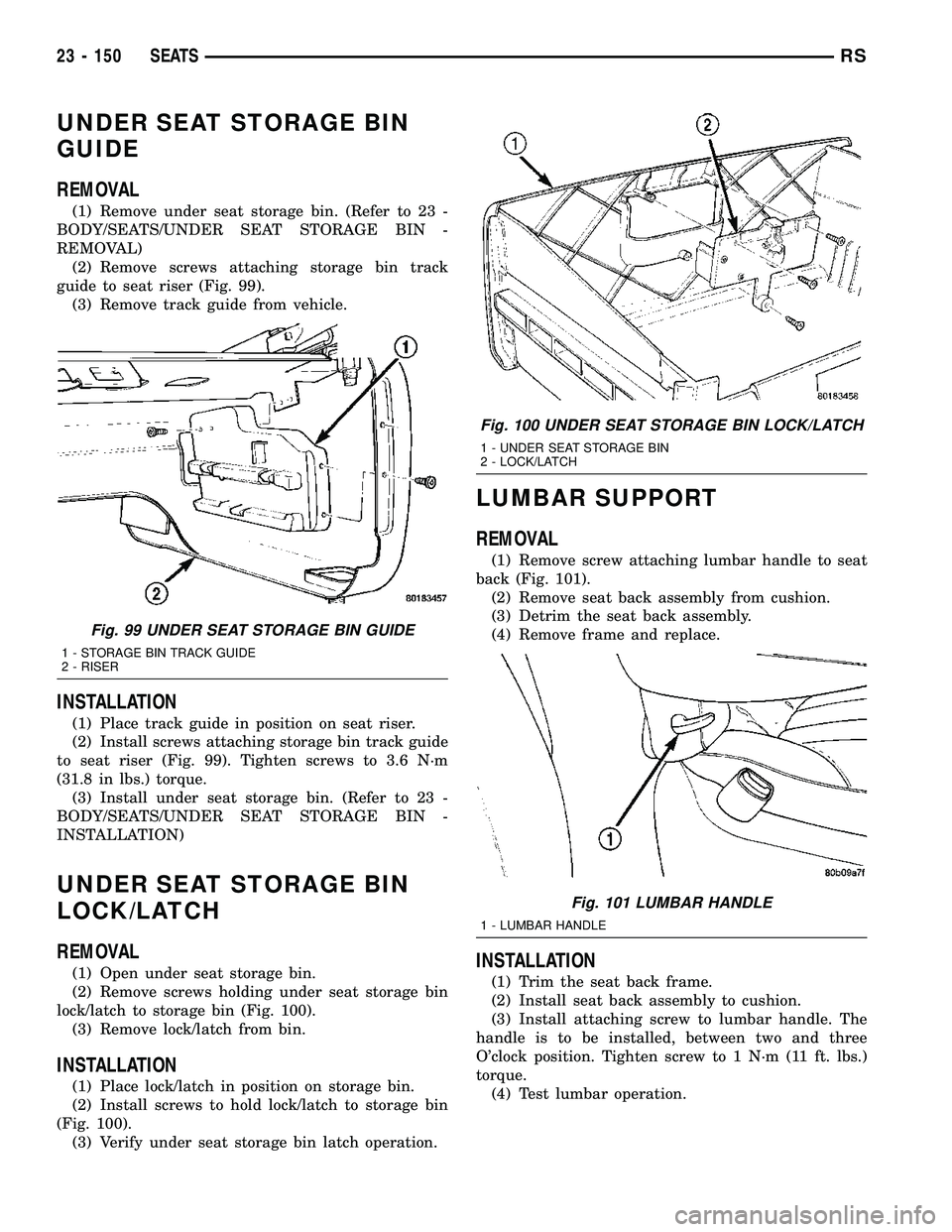
(2) Remove screws attaching storage bin track
guide to seat riser (Fig. 99).
(3) Remove track guide from vehicle.
INSTALLATION
(1) Place track guide in position on seat riser.
(2) Install screws attaching storage bin track guide
to seat riser (Fig. 99). Tighten screws to 3.6 N´m
(31.8 in lbs.) torque.
(3) Install under seat storage bin. (Refer to 23 -
BODY/SEATS/UNDER SEAT STORAGE BIN -
INSTALLATION)
UNDER SEAT STORAGE BIN
LOCK/LATCH
REMOVAL
(1) Open under seat storage bin.
(2) Remove screws holding under seat storage bin
lock/latch to storage bin (Fig. 100).
(3) Remove lock/latch from bin.
INSTALLATION
(1) Place lock/latch in position on storage bin.
(2) Install screws to hold lock/latch to storage bin
(Fig. 100).
(3) Verify under seat storage bin latch operation.
LUMBAR SUPPORT
REMOVAL
(1) Remove screw attaching lumbar handle to seat
back (Fig. 101).
(2) Remove seat back assembly from cushion.
(3) Detrim the seat back assembly.
(4) Remove frame and replace.
INSTALLATION
(1) Trim the seat back frame.
(2) Install seat back assembly to cushion.
(3) Install attaching screw to lumbar handle. The
handle is to be installed, between two and three
O'clock position. Tighten screw to 1 N´m (11 ft. lbs.)
torque.
(4) Test lumbar operation.
Fig. 99 UNDER SEAT STORAGE BIN GUIDE
1 - STORAGE BIN TRACK GUIDE
2 - RISER
Fig. 100 UNDER SEAT STORAGE BIN LOCK/LATCH
1 - UNDER SEAT STORAGE BIN
2 - LOCK/LATCH
Fig. 101 LUMBAR HANDLE
1 - LUMBAR HANDLE
23 - 150 SEATSRS
Page 1933 of 2339
INSTALLATION
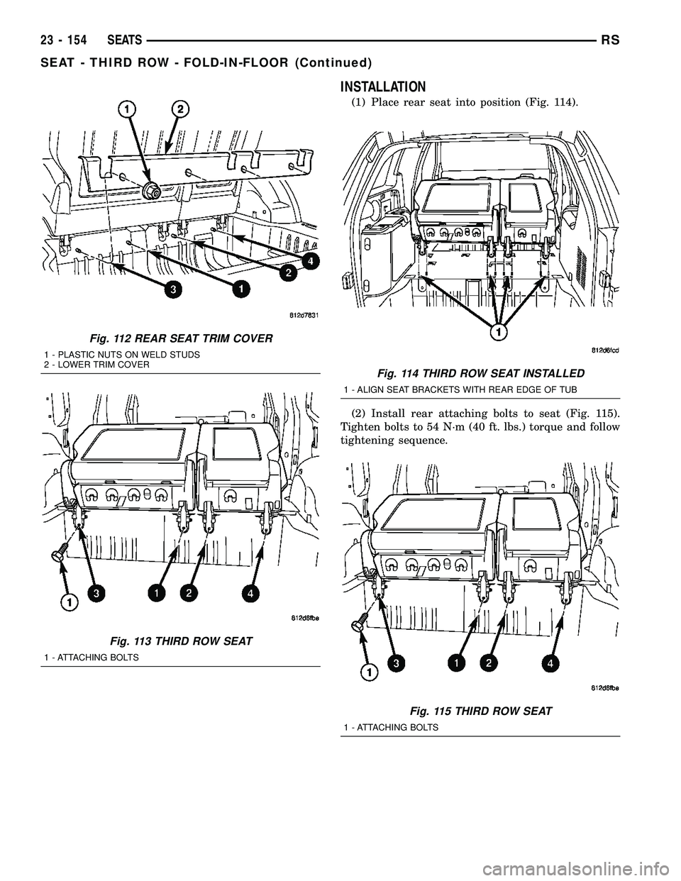
(1) Place rear seat into position (Fig. 114).
(2) Install rear attaching bolts to seat (Fig. 115).
Tighten bolts to 54 N´m (40 ft. lbs.) torque and follow
tightening sequence.
Fig. 112 REAR SEAT TRIM COVER
1 - PLASTIC NUTS ON WELD STUDS
2 - LOWER TRIM COVER
Fig. 113 THIRD ROW SEAT
1 - ATTACHING BOLTS
Fig. 114 THIRD ROW SEAT INSTALLED
1 - ALIGN SEAT BRACKETS WITH REAR EDGE OF TUB
Fig. 115 THIRD ROW SEAT
1 - ATTACHING BOLTS
23 - 154 SEATSRS
SEAT - THIRD ROW - FOLD-IN-FLOOR (Continued)