Page 1307 of 2339
(11) Install the timing chain cover (Refer to 9 -
ENGINE/VALVE TIMING/TIMING CHAIN COVER -
INSTALLATION).
(12) Install the oil pick-up tube and oil pan (Refer
to 9 - ENGINE/LUBRICATION/OIL PAN - INSTAL-
LATION).
(13) Install the transaxle to the engine.
(14) Install the engine assembly (Refer to 9 -
ENGINE - INSTALLATION).
CRANKSHAFT OIL SEAL -
FRONT
REMOVAL
(1) Disconnect negative cable from battery.(2) Raise vehicle on hoist. Remove right wheel and
inner splash shield.
(3) Remove accessory drive belt. (Refer to 7 -
COOLING/ACCESSORY DRIVE/DRIVE BELTS -
REMOVAL)
(4) Remove crankshaft damper. (Refer to 9 -
ENGINE/ENGINE BLOCK/VIBRATION DAMPER -
REMOVAL)
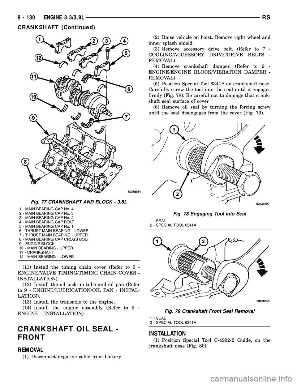
(5) Position Special Tool 6341A on crankshaft nose.
Carefully screw the tool into the seal until it engages
firmly (Fig. 78). Be careful not to damage that crank-
shaft seal surface of cover
(6) Remove oil seal by turning the forcing screw
until the seal disengages from the cover (Fig. 79).
INSTALLATION
(1) Position Special Tool C-4992-2 Guide, on the
crankshaft nose (Fig. 80).
Fig. 77 CRANKSHAFT AND BLOCK - 3.8L
1 - MAIN BEARING CAP No. 4
2 - MAIN BEARING CAP No. 3
3 - MAIN BEARING CAP No. 2
4 - MAIN BEARING CAP BOLT
5 - MAIN BEARING CAP No. 1
6 - THRUST MAIN BEARING - LOWER
7 - THRUST MAIN BEARING - UPPER
8 - MAIN BEARING CAP CROSS BOLT
9 - ENGINE BLOCK
10 - MAIN BEARING - UPPER
11 - CRANKSHAFT
12 - MAIN BEARING - LOWER
Fig. 78 Engaging Tool into Seal
1 - SEAL
2 - SPECIAL TOOL 6341A
Fig. 79 Crankshaft Front Seal Removal
1 - SEAL
2 - SPECIAL TOOL 6341A
9 - 130 ENGINE 3.3/3.8LRS
CRANKSHAFT (Continued)
Page 1308 of 2339
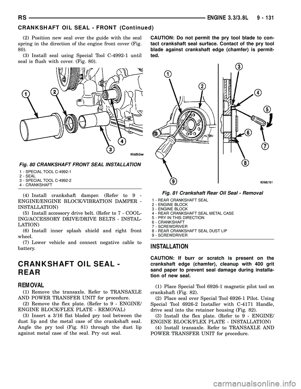
(2) Position new seal over the guide with the seal
spring in the direction of the engine front cover (Fig.
80).
(3) Install seal using Special Tool C-4992-1 until
seal is flush with cover. (Fig. 80).
(4) Install crankshaft damper. (Refer to 9 -
ENGINE/ENGINE BLOCK/VIBRATION DAMPER -
INSTALLATION)
(5) Install accessory drive belt. (Refer to 7 - COOL-
ING/ACCESSORY DRIVE/DRIVE BELTS - INSTAL-
LATION)
(6) Install inner splash shield and right front
wheel.
(7) Lower vehicle and connect negative cable to
battery.
CRANKSHAFT OIL SEAL -
REAR
REMOVAL
(1) Remove the transaxle. Refer to TRANSAXLE
AND POWER TRANSFER UNIT for procedure.
(2) Remove the flex plate. (Refer to 9 - ENGINE/
ENGINE BLOCK/FLEX PLATE - REMOVAL)
(3) Insert a 3/16 flat bladed pry tool between the
dust lip and the metal case of the crankshaft seal.
Angle the pry tool (Fig. 81) through the dust lip
against metal case of the seal. Pry out seal.CAUTION: Do not permit the pry tool blade to con-
tact crankshaft seal surface. Contact of the pry tool
blade against crankshaft edge (chamfer) is permit-
ted.
INSTALLATION
CAUTION: If burr or scratch is present on the
crankshaft edge (chamfer), cleanup with 400 grit
sand paper to prevent seal damage during installa-
tion of new seal.
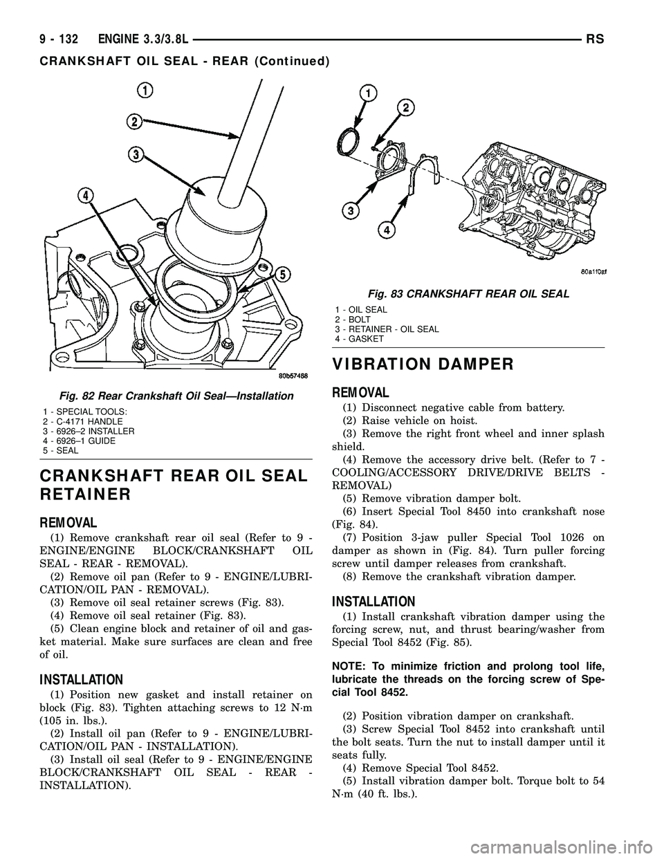
(1) Place Special Tool 6926-1 magnetic pilot tool on
crankshaft (Fig. 82).
(2) Place seal over Special Tool 6926-1 Pilot. Using
Special Tool 6926-2 Installer with C-4171 Handle,
drive seal into the retainer housing (Fig. 82).
(3) Install the flex plate. (Refer to 9 - ENGINE/
ENGINE BLOCK/FLEX PLATE - INSTALLATION)
(4) Install transaxle. Refer to TRANSAXLE AND
POWER TRANSFER UNIT for procedure.
Fig. 80 CRANKSHAFT FRONT SEAL INSTALLATION
1 - SPECIAL TOOL C-4992-1
2 - SEAL
3 - SPECIAL TOOL C-4992-2
4 - CRANKSHAFT
Fig. 81 Crankshaft Rear Oil Seal - Removal
1 - REAR CRANKSHAFT SEAL
2 - ENGINE BLOCK
3 - ENGINE BLOCK
4 - REAR CRANKSHAFT SEAL METAL CASE
5 - PRY IN THIS DIRECTION
6 - CRANKSHAFT
7 - SCREWDRIVER
8 - REAR CRANKSHAFT SEAL DUST LIP
9 - SCREWDRIVER
RSENGINE 3.3/3.8L9 - 131
CRANKSHAFT OIL SEAL - FRONT (Continued)
Page 1309 of 2339
CRANKSHAFT REAR OIL SEAL
RETAINER
REMOVAL
(1) Remove crankshaft rear oil seal (Refer to 9 -
ENGINE/ENGINE BLOCK/CRANKSHAFT OIL
SEAL - REAR - REMOVAL).
(2) Remove oil pan (Refer to 9 - ENGINE/LUBRI-
CATION/OIL PAN - REMOVAL).
(3) Remove oil seal retainer screws (Fig. 83).
(4) Remove oil seal retainer (Fig. 83).
(5) Clean engine block and retainer of oil and gas-
ket material. Make sure surfaces are clean and free
of oil.
INSTALLATION
(1) Position new gasket and install retainer on
block (Fig. 83). Tighten attaching screws to 12 N´m
(105 in. lbs.).
(2) Install oil pan (Refer to 9 - ENGINE/LUBRI-
CATION/OIL PAN - INSTALLATION).
(3) Install oil seal (Refer to 9 - ENGINE/ENGINE
BLOCK/CRANKSHAFT OIL SEAL - REAR -
INSTALLATION).
VIBRATION DAMPER
REMOVAL
(1) Disconnect negative cable from battery.
(2) Raise vehicle on hoist.
(3) Remove the right front wheel and inner splash
shield.
(4) Remove the accessory drive belt. (Refer to 7 -
COOLING/ACCESSORY DRIVE/DRIVE BELTS -
REMOVAL)
(5) Remove vibration damper bolt.
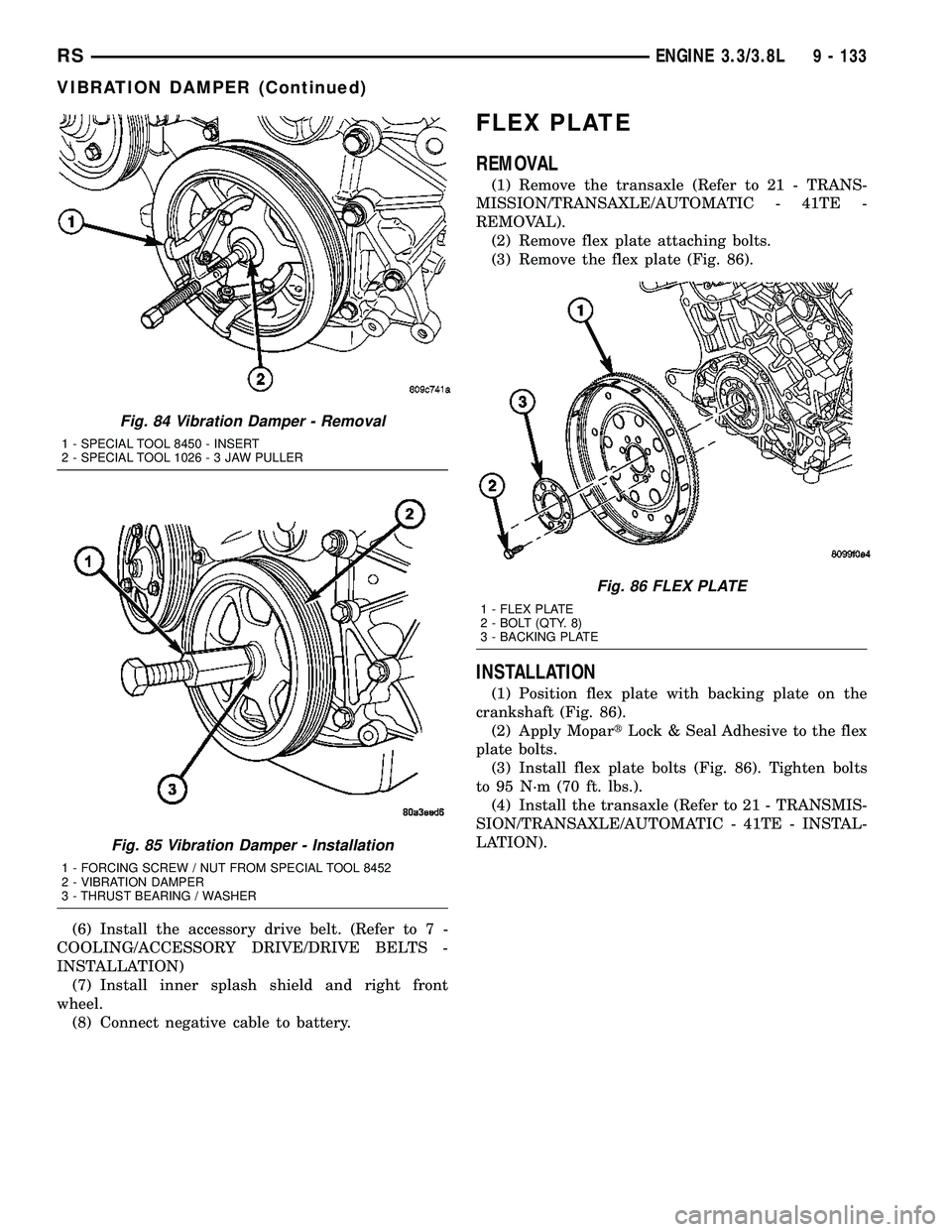
(6) Insert Special Tool 8450 into crankshaft nose
(Fig. 84).
(7) Position 3-jaw puller Special Tool 1026 on
damper as shown in (Fig. 84). Turn puller forcing
screw until damper releases from crankshaft.
(8) Remove the crankshaft vibration damper.
INSTALLATION
(1) Install crankshaft vibration damper using the
forcing screw, nut, and thrust bearing/washer from
Special Tool 8452 (Fig. 85).
NOTE: To minimize friction and prolong tool life,
lubricate the threads on the forcing screw of Spe-
cial Tool 8452.
(2) Position vibration damper on crankshaft.
(3) Screw Special Tool 8452 into crankshaft until
the bolt seats. Turn the nut to install damper until it
seats fully.
(4) Remove Special Tool 8452.
(5) Install vibration damper bolt. Torque bolt to 54
N´m (40 ft. lbs.).
Fig. 82 Rear Crankshaft Oil SealÐInstallation
1 - SPECIAL TOOLS:
2 - C-4171 HANDLE
3 - 6926±2 INSTALLER
4 - 6926±1 GUIDE
5 - SEAL
Fig. 83 CRANKSHAFT REAR OIL SEAL
1 - OIL SEAL
2 - BOLT
3 - RETAINER - OIL SEAL
4 - GASKET
9 - 132 ENGINE 3.3/3.8LRS
CRANKSHAFT OIL SEAL - REAR (Continued)
Page 1310 of 2339
(6) Install the accessory drive belt. (Refer to 7 -
COOLING/ACCESSORY DRIVE/DRIVE BELTS -
INSTALLATION)
(7) Install inner splash shield and right front
wheel.
(8) Connect negative cable to battery.
FLEX PLATE
REMOVAL
(1) Remove the transaxle (Refer to 21 - TRANS-
MISSION/TRANSAXLE/AUTOMATIC - 41TE -
REMOVAL).
(2) Remove flex plate attaching bolts.
(3) Remove the flex plate (Fig. 86).
INSTALLATION
(1) Position flex plate with backing plate on the
crankshaft (Fig. 86).
(2) Apply MopartLock & Seal Adhesive to the flex
plate bolts.
(3) Install flex plate bolts (Fig. 86). Tighten bolts
to 95 N´m (70 ft. lbs.).
(4) Install the transaxle (Refer to 21 - TRANSMIS-
SION/TRANSAXLE/AUTOMATIC - 41TE - INSTAL-
LATION).
Fig. 84 Vibration Damper - Removal
1 - SPECIAL TOOL 8450 - INSERT
2 - SPECIAL TOOL 1026-3JAWPULLER
Fig. 85 Vibration Damper - Installation
1 - FORCING SCREW / NUT FROM SPECIAL TOOL 8452
2 - VIBRATION DAMPER
3 - THRUST BEARING / WASHER
Fig. 86 FLEX PLATE
1 - FLEX PLATE
2 - BOLT (QTY. 8)
3 - BACKING PLATE
RSENGINE 3.3/3.8L9 - 133
VIBRATION DAMPER (Continued)
Page 1311 of 2339
ENGINE MOUNTING
DESCRIPTION
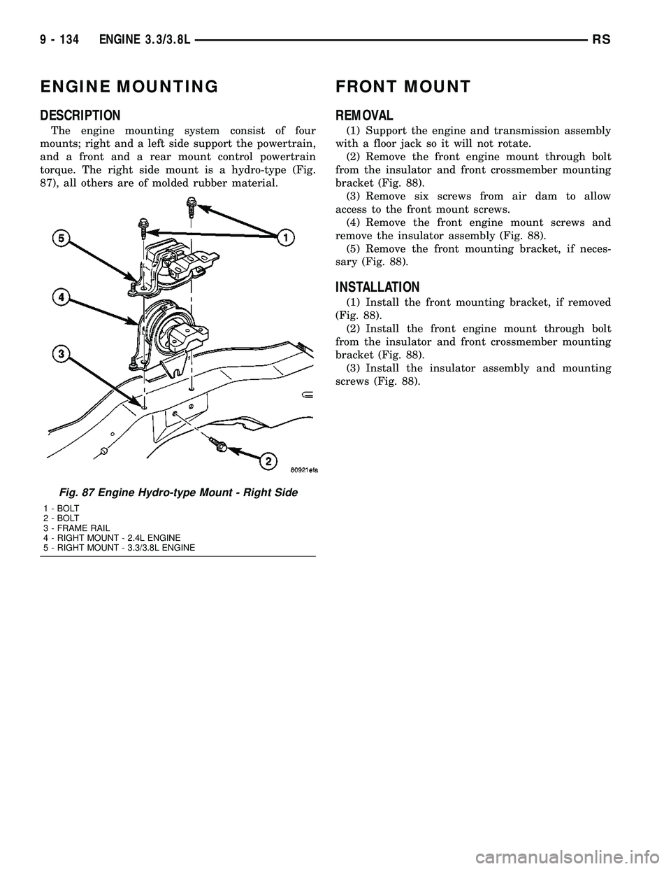
The engine mounting system consist of four
mounts; right and a left side support the powertrain,
and a front and a rear mount control powertrain
torque. The right side mount is a hydro-type (Fig.
87), all others are of molded rubber material.
FRONT MOUNT
REMOVAL
(1) Support the engine and transmission assembly
with a floor jack so it will not rotate.
(2) Remove the front engine mount through bolt
from the insulator and front crossmember mounting
bracket (Fig. 88).
(3) Remove six screws from air dam to allow
access to the front mount screws.
(4) Remove the front engine mount screws and
remove the insulator assembly (Fig. 88).
(5) Remove the front mounting bracket, if neces-
sary (Fig. 88).
INSTALLATION
(1) Install the front mounting bracket, if removed
(Fig. 88).
(2) Install the front engine mount through bolt
from the insulator and front crossmember mounting
bracket (Fig. 88).
(3) Install the insulator assembly and mounting
screws (Fig. 88).
Fig. 87 Engine Hydro-type Mount - Right Side
1 - BOLT
2 - BOLT
3 - FRAME RAIL
4 - RIGHT MOUNT - 2.4L ENGINE
5 - RIGHT MOUNT - 3.3/3.8L ENGINE
9 - 134 ENGINE 3.3/3.8LRS
Page 1312 of 2339
Fig. 88 Engine Mounting - Front
1 - CROSSMEMBER 5 - BOLT 54 N´m (40 ft. lbs.)
2 - BOLT - 68 N´m (50 ft. lbs.) 6 - NUT - 68 N´m (50 ft. lbs.)
3 - BOLT - 102 N´m (75 ft. lbs.) 7 - MOUNT - ENGINE FRONT
4 - BOLT - 68 N´m (50 ft. lbs.) 8 - BRACKET - ENGINE FRONT MOUNT
RSENGINE 3.3/3.8L9 - 135
FRONT MOUNT (Continued)
Page 1313 of 2339
LEFT MOUNT
REMOVAL
(1) Raise the vehicle on hoist.
(2) Remove the left front wheel.
(3) Remove the left mount through bolt access
cover.
(4) Support the transaxle with a suitable jack.
(5) Remove the engine front mount through bolt to
allow left mount removal clearance (Fig. 88).
(6) Remove the left mount through frame rail bolt
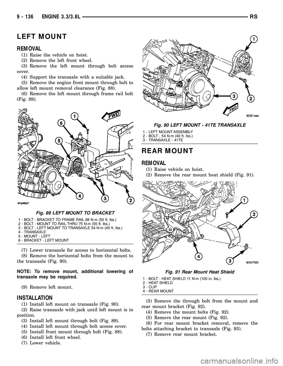
(Fig. 89).
(7) Lower transaxle for access to horizontal bolts.
(8) Remove the horizontal bolts from the mount to
the transaxle (Fig. 90).
NOTE: To remove mount, additional lowering of
transaxle may be required.
(9) Remove left mount.
INSTALLATION
(1) Install left mount on transaxle (Fig. 90).
(2) Raise transaxle with jack until left mount is in
position.
(3) Install left mount through bolt (Fig. 89).
(4) Install left mount through bolt access cover.
(5) Install front mount through bolt (Fig. 88).
(6) Install left front wheel.
(7) Lower vehicle.
REAR MOUNT
REMOVAL
(1) Raise vehicle on hoist.
(2) Remove the rear mount heat shield (Fig. 91).
(3) Remove the through bolt from the mount and
rear mount bracket (Fig. 92).
(4) Remove the mount bolts (Fig. 92).
(5) Remove the rear mount (Fig. 92).
(6) For rear mount bracket removal, remove the
bolts attaching bracket to transaxle (Fig. 93).
(7) Remove rear mount bracket.
Fig. 89 LEFT MOUNT TO BRACKET
1 - BOLT - BRACKET TO FRAME RAIL 68 N´m (50 ft. lbs.)
2 - BOLT - MOUNT TO RAIL THRU 75 N´m (55 ft. lbs.)
3 - BOLT - LEFT MOUNT TO TRANSAXLE 54 N´m (40 ft. lbs.)
4 - TRANSAXLE
5 - MOUNT - LEFT
6 - BRACKET - LEFT MOUNT
Fig. 90 LEFT MOUNT - 41TE TRANSAXLE
1 - LEFT MOUNT ASSEMBLY
2 - BOLT - 54 N´m (40 ft. lbs.)
3 - TRANSAXLE - 41TE
Fig. 91 Rear Mount Heat Shield
1 - BOLT - HEAT SHIELD 11 N´m (100 in. lbs.)
2 - HEAT SHIELD
3 - CLIP
4 - REAR MOUNT
9 - 136 ENGINE 3.3/3.8LRS
Page 1314 of 2339
INSTALLATION
(1) Install rear mount bracket, if removed (Fig.
93).
(2) Install the rear mount and bolts (Fig. 92).
Tighten bolts to 54 N´m (40 ft. lbs.).
(3) Install the mount through bolt to the mount
and bracket (Fig. 92). Tighten through bolt to 54 N´m
(40 ft. lbs.).
(4) Install the rear mount heat shield (Fig. 91).
(5) Lower vehicle on hoist.
Fig. 92 Rear Mount
1 - BOLT 54 N´m (40 ft. lbs.)
2 - REAR MOUNT BRACKET
3 - THRU-BOLT 54 N´m (40 ft. lbs.)
4 - REAR MOUNT
Fig. 93 Rear Mount Bracket - (all engines)
1 - BOLT - VERTICAL 102 N´m (75 ft. lbs.)
2 - BRACKET - REAR MOUNT3 - BOLT - HORIZONTAL 102 N´m (75 ft. lbs.)
RSENGINE 3.3/3.8L9 - 137
REAR MOUNT (Continued)