2005 CHRYSLER VOYAGER check engine light
[x] Cancel search: check engine lightPage 1265 of 2339
(3) Place a shop towel around the spark plugs
when removing them from the engine. This will catch
any fluid that may possibly be in the cylinder under
pressure.
(4) With all spark plugs removed, rotate engine
crankshaft using a breaker bar and socket.
(5) Identify the fluid in the cylinder(s) (i.e., cool-
ant, fuel, oil or other).
(6) Make sure all fluid has been removed from the
cylinders. Inspect engine for damage (i.e., connecting
rods, pistons, valves, etc.)
(7) Repair engine or components as necessary to
prevent this problem from re-occurring.
CAUTION: Squirt approximately one teaspoon of oil
into the cylinders, rotate engine to lubricate the cyl-
inder walls to prevent damage on restart.
(8) Install new spark plugs.
(9) Drain engine oil and remove oil filter.
(10) Install a new oil filter.
(11) Fill engine with specified amount of approved
oil.
(12) Connect negative battery cable.
(13) Start engine and check for any leaks.
STANDARD PROCEDURE - REPAIR OF
DAMAGED OR WORN THREADS
Damaged or worn threads (excluding spark plug
and camshaft bearing cap attaching threads) can be
repaired. Essentially, this repair consists of drilling
out worn or damaged threads, tapping the hole with
a special Heli-Coil Tap, (or equivalent) and installing
an insert into the tapped hole. This brings the hole
back to its original thread size.
CAUTION: Be sure that the tapped holes maintain
the original center line.
Heli-Coil tools and inserts are readily available
from automotive parts jobbers.
STANDARD PROCEDURE - ENGINE CORE AND
OIL GALLERY PLUGS
Using a blunt tool such as a drift and a hammer,
strike the bottom edge of the cup plug. With the cup
plug rotated, grasp firmly with pliers or other suit-
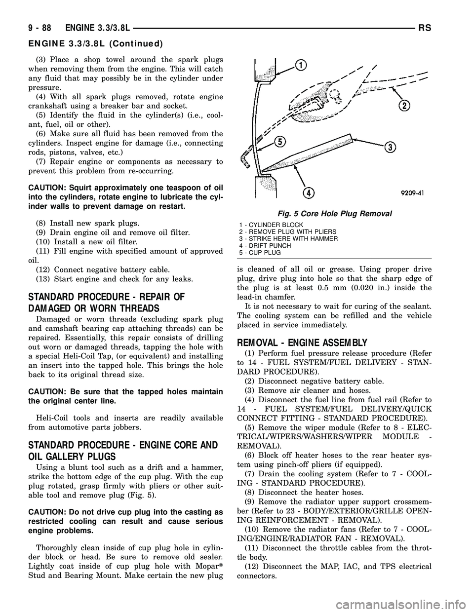
able tool and remove plug (Fig. 5).
CAUTION: Do not drive cup plug into the casting as
restricted cooling can result and cause serious
engine problems.
Thoroughly clean inside of cup plug hole in cylin-
der block or head. Be sure to remove old sealer.
Lightly coat inside of cup plug hole with Mopart
Stud and Bearing Mount. Make certain the new plugis cleaned of all oil or grease. Using proper drive
plug, drive plug into hole so that the sharp edge of
the plug is at least 0.5 mm (0.020 in.) inside the
lead-in chamfer.
It is not necessary to wait for curing of the sealant.
The cooling system can be refilled and the vehicle
placed in service immediately.
REMOVAL - ENGINE ASSEMBLY
(1) Perform fuel pressure release procedure (Refer
to 14 - FUEL SYSTEM/FUEL DELIVERY - STAN-
DARD PROCEDURE).
(2) Disconnect negative battery cable.
(3) Remove air cleaner and hoses.
(4) Disconnect the fuel line from fuel rail (Refer to
14 - FUEL SYSTEM/FUEL DELIVERY/QUICK
CONNECT FITTING - STANDARD PROCEDURE).
(5) Remove the wiper module (Refer to 8 - ELEC-
TRICAL/WIPERS/WASHERS/WIPER MODULE -
REMOVAL).
(6) Block off heater hoses to the rear heater sys-
tem using pinch-off pliers (if equipped).
(7) Drain the cooling system (Refer to 7 - COOL-
ING - STANDARD PROCEDURE).
(8) Disconnect the heater hoses.
(9) Remove the radiator upper support crossmem-
ber (Refer to 23 - BODY/EXTERIOR/GRILLE OPEN-
ING REINFORCEMENT - REMOVAL).
(10) Remove the radiator fans (Refer to 7 - COOL-
ING/ENGINE/RADIATOR FAN - REMOVAL).
(11) Disconnect the throttle cables from the throt-
tle body.
(12) Disconnect the MAP, IAC, and TPS electrical
connectors.
Fig. 5 Core Hole Plug Removal
1 - CYLINDER BLOCK
2 - REMOVE PLUG WITH PLIERS
3 - STRIKE HERE WITH HAMMER
4 - DRIFT PUNCH
5 - CUP PLUG
9 - 88 ENGINE 3.3/3.8LRS
ENGINE 3.3/3.8L (Continued)
Page 1292 of 2339
REMOVAL
(1) Remove the valve springs. (Refer to 9 -
ENGINE/CYLINDER HEAD/VALVE SPRINGS -
REMOVAL)
(2) Remove the valve stem seal (Fig. 44).
INSTALLATION
(1) Install the valve stem seal squarely over the
valve guide, using the valve stem as a guide (Fig.
44). Do not force the seal against top of the valve
guide.
(2) Install the valve spring. (Refer to 9 - ENGINE/
CYLINDER HEAD/VALVE SPRINGS - INSTALLA-
TION)
ENGINE BLOCK
DESCRIPTION
The cylinder block is made of cast iron and is a
deep skirt design.
STANDARD PROCEDURE - CYLINDER BORE
HONING
(1) Used carefully, the cylinder bore resizing hone,
recommended tool C-823 or equivalent, equipped
with 220 grit stones, is the best tool for this honing
procedure. In addition to deglazing, it will reduce
taper and out-of-round as well as removing light
scuffing, scoring or scratches. Usually a few strokes
will clean up a bore and maintain the required lim-
its.
(2) Deglazing of the cylinder walls may be done
using a cylinder surfacing hone, recommended tool
C-3501 or equivalent, equipped with 280 grit stones,
if the cylinder bore is straight and round. 20±60
strokes depending on the bore condition, will be suf-
ficient to provide a satisfactory surface. Use a light
honing oil.Do not use engine or transmission oil,
mineral spirits or kerosene.Inspect cylinder walls
after each 20 strokes.
(3) Honing should be done by moving the hone up
and down fast enough to get a cross-hatch pattern.
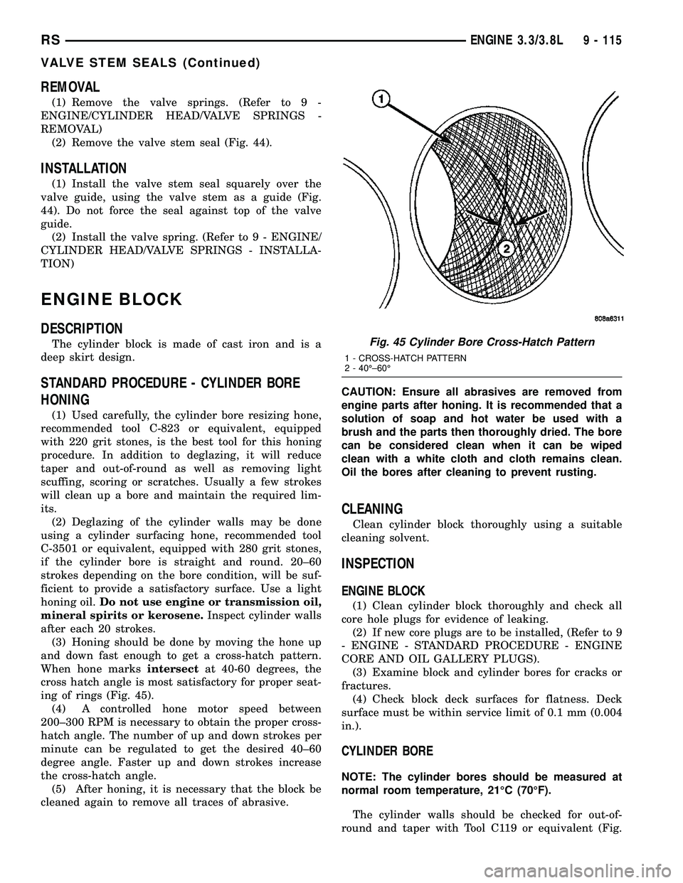
When hone marksintersectat 40-60 degrees, the
cross hatch angle is most satisfactory for proper seat-
ing of rings (Fig. 45).
(4) A controlled hone motor speed between
200±300 RPM is necessary to obtain the proper cross-
hatch angle. The number of up and down strokes per
minute can be regulated to get the desired 40±60
degree angle. Faster up and down strokes increase
the cross-hatch angle.
(5) After honing, it is necessary that the block be
cleaned again to remove all traces of abrasive.CAUTION: Ensure all abrasives are removed from
engine parts after honing. It is recommended that a
solution of soap and hot water be used with a
brush and the parts then thoroughly dried. The bore
can be considered clean when it can be wiped
clean with a white cloth and cloth remains clean.
Oil the bores after cleaning to prevent rusting.
CLEANING
Clean cylinder block thoroughly using a suitable
cleaning solvent.
INSPECTION
ENGINE BLOCK
(1) Clean cylinder block thoroughly and check all
core hole plugs for evidence of leaking.
(2) If new core plugs are to be installed, (Refer to 9
- ENGINE - STANDARD PROCEDURE - ENGINE
CORE AND OIL GALLERY PLUGS).
(3) Examine block and cylinder bores for cracks or
fractures.
(4) Check block deck surfaces for flatness. Deck
surface must be within service limit of 0.1 mm (0.004
in.).
CYLINDER BORE
NOTE: The cylinder bores should be measured at
normal room temperature, 21ÉC (70ÉF).
The cylinder walls should be checked for out-of-
round and taper with Tool C119 or equivalent (Fig.
Fig. 45 Cylinder Bore Cross-Hatch Pattern
1 - CROSS-HATCH PATTERN
2 - 40ɱ60É
RSENGINE 3.3/3.8L9 - 115
VALVE STEM SEALS (Continued)
Page 1293 of 2339
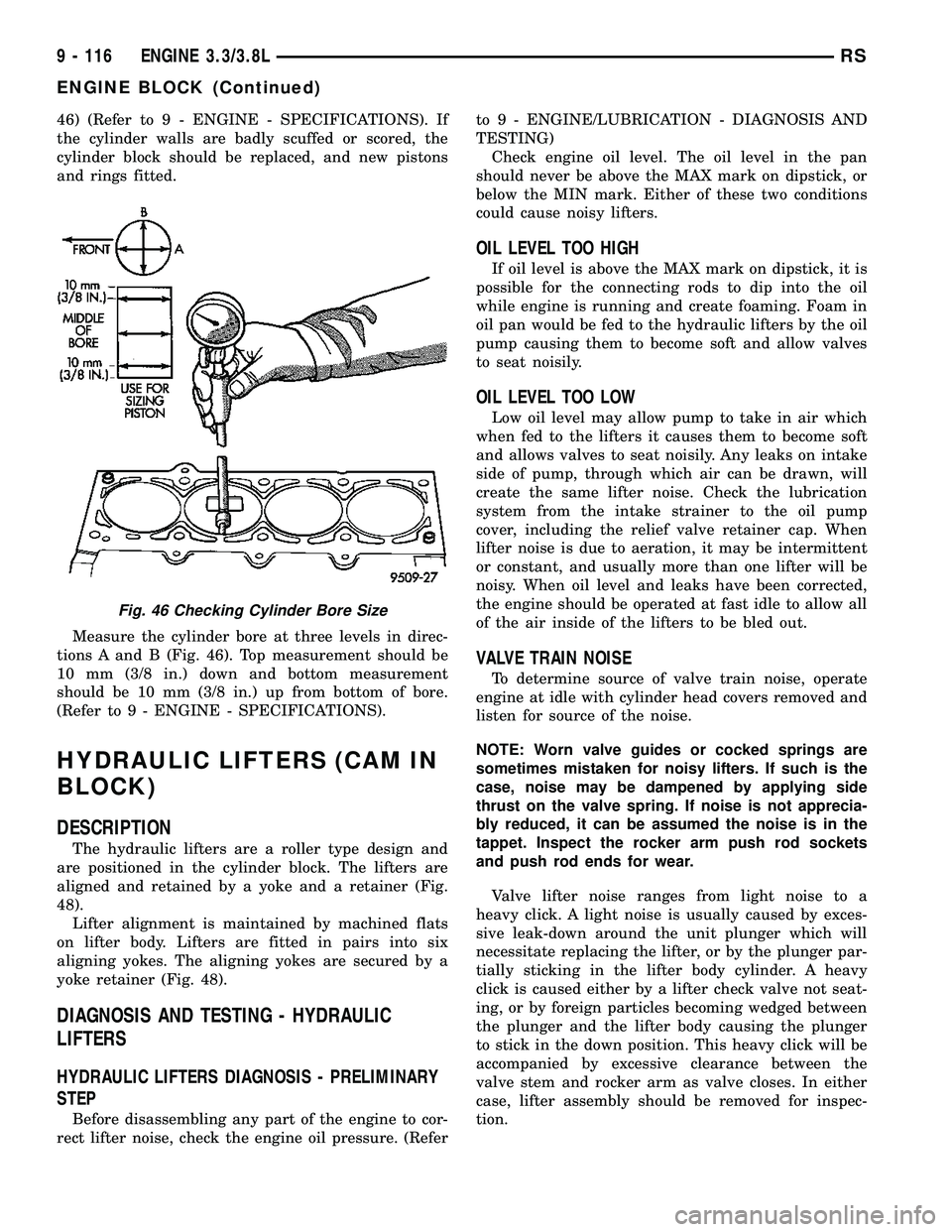
46) (Refer to 9 - ENGINE - SPECIFICATIONS). If
the cylinder walls are badly scuffed or scored, the
cylinder block should be replaced, and new pistons
and rings fitted.
Measure the cylinder bore at three levels in direc-
tions A and B (Fig. 46). Top measurement should be
10 mm (3/8 in.) down and bottom measurement
should be 10 mm (3/8 in.) up from bottom of bore.
(Refer to 9 - ENGINE - SPECIFICATIONS).
HYDRAULIC LIFTERS (CAM IN
BLOCK)
DESCRIPTION
The hydraulic lifters are a roller type design and
are positioned in the cylinder block. The lifters are
aligned and retained by a yoke and a retainer (Fig.
48).
Lifter alignment is maintained by machined flats
on lifter body. Lifters are fitted in pairs into six
aligning yokes. The aligning yokes are secured by a
yoke retainer (Fig. 48).
DIAGNOSIS AND TESTING - HYDRAULIC
LIFTERS
HYDRAULIC LIFTERS DIAGNOSIS - PRELIMINARY
STEP
Before disassembling any part of the engine to cor-
rect lifter noise, check the engine oil pressure. (Referto 9 - ENGINE/LUBRICATION - DIAGNOSIS AND
TESTING)
Check engine oil level. The oil level in the pan
should never be above the MAX mark on dipstick, or
below the MIN mark. Either of these two conditions
could cause noisy lifters.
OIL LEVEL TOO HIGH
If oil level is above the MAX mark on dipstick, it is
possible for the connecting rods to dip into the oil
while engine is running and create foaming. Foam in
oil pan would be fed to the hydraulic lifters by the oil
pump causing them to become soft and allow valves
to seat noisily.
OIL LEVEL TOO LOW
Low oil level may allow pump to take in air which
when fed to the lifters it causes them to become soft
and allows valves to seat noisily. Any leaks on intake
side of pump, through which air can be drawn, will
create the same lifter noise. Check the lubrication
system from the intake strainer to the oil pump
cover, including the relief valve retainer cap. When
lifter noise is due to aeration, it may be intermittent
or constant, and usually more than one lifter will be
noisy. When oil level and leaks have been corrected,
the engine should be operated at fast idle to allow all
of the air inside of the lifters to be bled out.
VALVE TRAIN NOISE
To determine source of valve train noise, operate
engine at idle with cylinder head covers removed and
listen for source of the noise.
NOTE: Worn valve guides or cocked springs are
sometimes mistaken for noisy lifters. If such is the
case, noise may be dampened by applying side
thrust on the valve spring. If noise is not apprecia-
bly reduced, it can be assumed the noise is in the
tappet. Inspect the rocker arm push rod sockets
and push rod ends for wear.
Valve lifter noise ranges from light noise to a
heavy click. A light noise is usually caused by exces-
sive leak-down around the unit plunger which will
necessitate replacing the lifter, or by the plunger par-
tially sticking in the lifter body cylinder. A heavy
click is caused either by a lifter check valve not seat-
ing, or by foreign particles becoming wedged between
the plunger and the lifter body causing the plunger
to stick in the down position. This heavy click will be
accompanied by excessive clearance between the
valve stem and rocker arm as valve closes. In either
case, lifter assembly should be removed for inspec-
tion.
Fig. 46 Checking Cylinder Bore Size
9 - 116 ENGINE 3.3/3.8LRS
ENGINE BLOCK (Continued)
Page 1321 of 2339
INSTALLATION
(1) Clean relief valve, spring and bore.
NOTE: Lubricate relief valve with clean engine oil
before installing.
(2) Install relief valve and spring into housing.
(3) Install new retainer cap until flush with seal-
ing surface.
(4) Install oil pan (Refer to 9 - ENGINE/LUBRI-
CATION/OIL PAN - INSTALLATION).
(5) Fill crankcase with proper oil to correct level.
OIL PRESSURE SWITCH
DESCRIPTION
The engine oil pressure switch is located on the
lower left front side of the engine. It screws into the
oil filter adapter. The normally closed switch provides
an input through a single wire to the low pressure
indicator light on the instrument cluster.
OPERATION
The oil pressure switch provides a ground for the
instrument cluster low oil pressure indicator light.
The switch receives oil pressure input from the
engine main oil gallery. When engine oil pressure is
greater than 27.5 Kpa (4 psi), the switch contacts
open, providing a open circuit to the low pressure
indicator light. For wiring circuits and diagnostic
information, (Refer to Appropriate Wiring/Diagnostic
Information).
REMOVAL
(1) Raise vehicle on hoist.
(2) Disconnect electrical connector from switch.
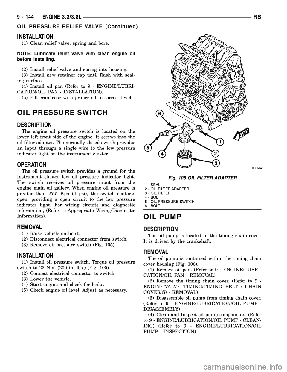
(3) Remove oil pressure switch (Fig. 105).
INSTALLATION
(1) Install oil pressure switch. Torque oil pressure
switch to 23 N´m (200 in. lbs.) (Fig. 105).
(2) Connect electrical connector to switch.
(3) Lower the vehicle.
(4) Start engine and check for leaks.
(5) Check engine oil level. Adjust as necessary.
OIL PUMP
DESCRIPTION
The oil pump is located in the timing chain cover.
It is driven by the crankshaft.
REMOVAL
The oil pump is contained within the timing chain
cover housing (Fig. 106).
(1) Remove oil pan. (Refer to 9 - ENGINE/LUBRI-
CATION/OIL PAN - REMOVAL)
(2) Remove the timing chain cover. (Refer to 9 -
ENGINE/VALVE TIMING/TIMING BELT / CHAIN
COVER(S) - REMOVAL)
(3) Disassemble oil pump from timing chain cover.
(Refer to 9 - ENGINE/LUBRICATION/OIL PUMP -
DISASSEMBLY)
(4) Clean and Inspect oil pump components. (Refer
to 9 - ENGINE/LUBRICATION/OIL PUMP - CLEAN-
ING) (Refer to 9 - ENGINE/LUBRICATION/OIL
PUMP - INSPECTION)
Fig. 105 OIL FILTER ADAPTER
1 - SEAL
2 - OIL FILTER ADAPTER
3 - OIL FILTER
4 - BOLT
5 - OIL PRESSURE SWITCH
6 - BOLT
9 - 144 ENGINE 3.3/3.8LRS
OIL PRESSURE RELIEF VALVE (Continued)
Page 1326 of 2339
INSPECTION
Check manifold for:
²Damage and cracks.
²Mounting surface distortion by using a straight-
edge and thickness gauge.
INSTALLATION - UPPER INTAKE MANIFOLD
(1) If the following components were removed from
manifold, install and tighten to specifications:
CAUTION: The special screws used for the compos-
ite manifold attached components must be installed
slowly using hand tools only. This requirement is to
prevent the melting of material that causes stripped
threads. If threads become stripped, an oversize
repair screw is available. For more information and
procedure (Refer to 9 - ENGINE/MANIFOLDS/IN-
TAKE MANIFOLD - STANDARD PROCEDURE - MAN-
IFOLD STRIPPED THREAD REPAIR).
²MAP sensor - 1.7 N´m (15 in. lbs.)
²Throttle cable bracket - 5.6 N´m (50 in. lbs.)
(2) Remove covering on lower intake manifold and
clean surfaces.
(3) Inspect manifold gasket condition. Gaskets can
be re-used, if not damaged. To replace, remove gasket
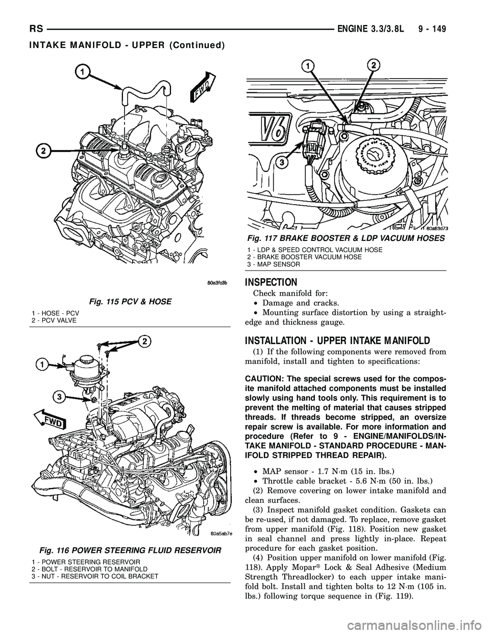
from upper manifold (Fig. 118). Position new gasket
in seal channel and press lightly in-place. Repeat
procedure for each gasket position.
(4) Position upper manifold on lower manifold (Fig.
118). Apply MopartLock & Seal Adhesive (Medium
Strength Threadlocker) to each upper intake mani-
fold bolt. Install and tighten bolts to 12 N´m (105 in.
lbs.) following torque sequence in (Fig. 119).
Fig. 115 PCV & HOSE
1 - HOSE - PCV
2 - P C V VA LV E
Fig. 116 POWER STEERING FLUID RESERVOIR
1 - POWER STEERING RESERVOIR
2 - BOLT - RESERVOIR TO MANIFOLD
3 - NUT - RESERVOIR TO COIL BRACKET
Fig. 117 BRAKE BOOSTER & LDP VACUUM HOSES
1 - LDP & SPEED CONTROL VACUUM HOSE
2 - BRAKE BOOSTER VACUUM HOSE
3 - MAP SENSOR
RSENGINE 3.3/3.8L9 - 149
INTAKE MANIFOLD - UPPER (Continued)
Page 1343 of 2339
INSPECTION
WARNING: THE NORMAL OPERATING TEMPERA-
TURE OF THE EXHAUST SYSTEM IS VERY HIGH.
THEREFORE, NEVER ATTEMPT TO SERVICE ANY
PART OF THE EXHAUST SYSTEM UNTIL IT IS
COOLED. SPECIAL CARE SHOULD BE TAKEN
WHEN WORKING NEAR THE CATALYTIC CON-
VERTER. THE TEMPERATURE OF THE CONVERTER
RISES TO A HIGH LEVEL AFTER A SHORT PERIOD
OF ENGINE OPERATION TIME.
Check catalytic converter for a flow restriction.
(Refer to 11 - EXHAUST SYSTEM - DIAGNOSIS
AND TESTING) Exhaust System Restriction Check
for procedure.
Visually inspect the catalytic converter element by
using a borescope or equivalent. Remove oxygen sen-
sor(s) and insert borescope. If borescope is not avail-
able, remove converter and inspect element using a
flashlight. Inspect element for cracked or melted sub-
strate.
NOTE: Before replacing a catalytic converter, deter-
mine the root cause of failure. Most catalytic con-
verter failures are caused by air, fuel or ignition
problems. (Refer to Appropriate Diagnostic Informa-
tion) for test procedures.
INSTALLATION
(1) Position new gasket onto the manifold flange
and install catalytic converter (Fig. 5). Tighten fas-
teners to 37 N´m (325 in. lbs.).
NOTE: Be careful not to twist or kink the oxygen
sensor wires.
(2) Install (if removed) and connect the down-
stream oxygen sensor (Fig. 4).
(3) Install the muffler/resonator assembly. (Refer
to 11 - EXHAUST SYSTEM/MUFFLER - INSTALLA-
TION)
(4) Start the engine and inspect for exhaust leaks.
Repair exhaust leaks as necessary.
(5) Check the exhaust system for contact with the
body panels. Make the necessary adjustments, if
needed.
CROSS-OVER PIPE - 3.3/3.8L
REMOVAL
(1) Disconnect negative cable from battery.
(2) Remove the fasteners attaching the left bank
manifold connection to cross-over pipe (Fig. 6).
(3) Raise vehicle and remove the left front wheel.(4) Access the lower right bank pipe connection
fastener through the left front wheel opening using a
long ratchet extension. Loosen and remove the lower
fastener.
(5) Remove the upper right bank pipe connection
fastener by accessing though the catalytic converter
floor pan tunnel.
(6) Lower the vehicle.
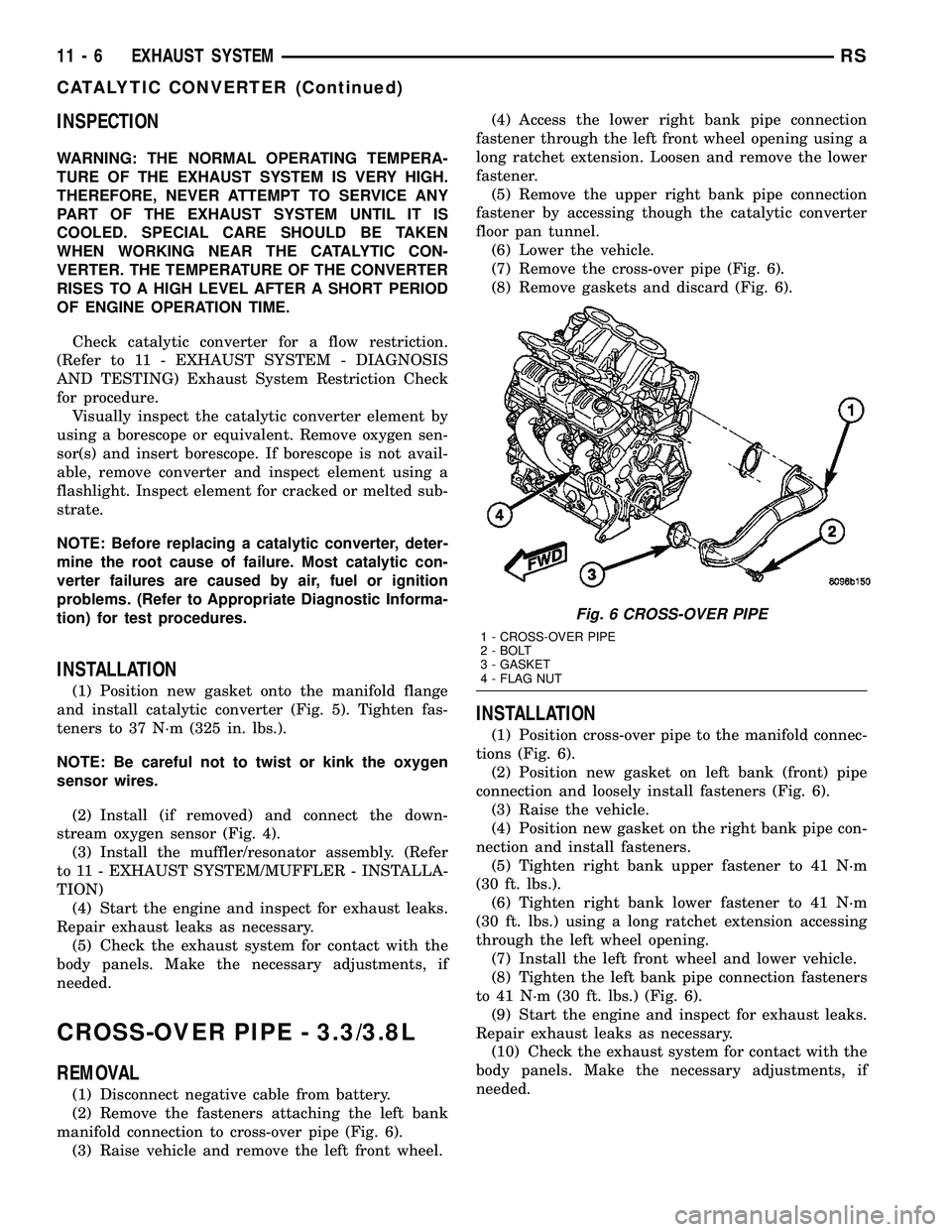
(7) Remove the cross-over pipe (Fig. 6).
(8) Remove gaskets and discard (Fig. 6).
INSTALLATION
(1) Position cross-over pipe to the manifold connec-
tions (Fig. 6).
(2) Position new gasket on left bank (front) pipe
connection and loosely install fasteners (Fig. 6).
(3) Raise the vehicle.
(4) Position new gasket on the right bank pipe con-
nection and install fasteners.
(5) Tighten right bank upper fastener to 41 N´m
(30 ft. lbs.).
(6) Tighten right bank lower fastener to 41 N´m
(30 ft. lbs.) using a long ratchet extension accessing
through the left wheel opening.
(7) Install the left front wheel and lower vehicle.
(8) Tighten the left bank pipe connection fasteners
to 41 N´m (30 ft. lbs.) (Fig. 6).
(9) Start the engine and inspect for exhaust leaks.
Repair exhaust leaks as necessary.
(10) Check the exhaust system for contact with the
body panels. Make the necessary adjustments, if
needed.
Fig. 6 CROSS-OVER PIPE
1 - CROSS-OVER PIPE
2 - BOLT
3 - GASKET
4 - FLAG NUT
11 - 6 EXHAUST SYSTEMRS
CATALYTIC CONVERTER (Continued)
Page 1344 of 2339
HEAT SHIELDS
DESCRIPTION
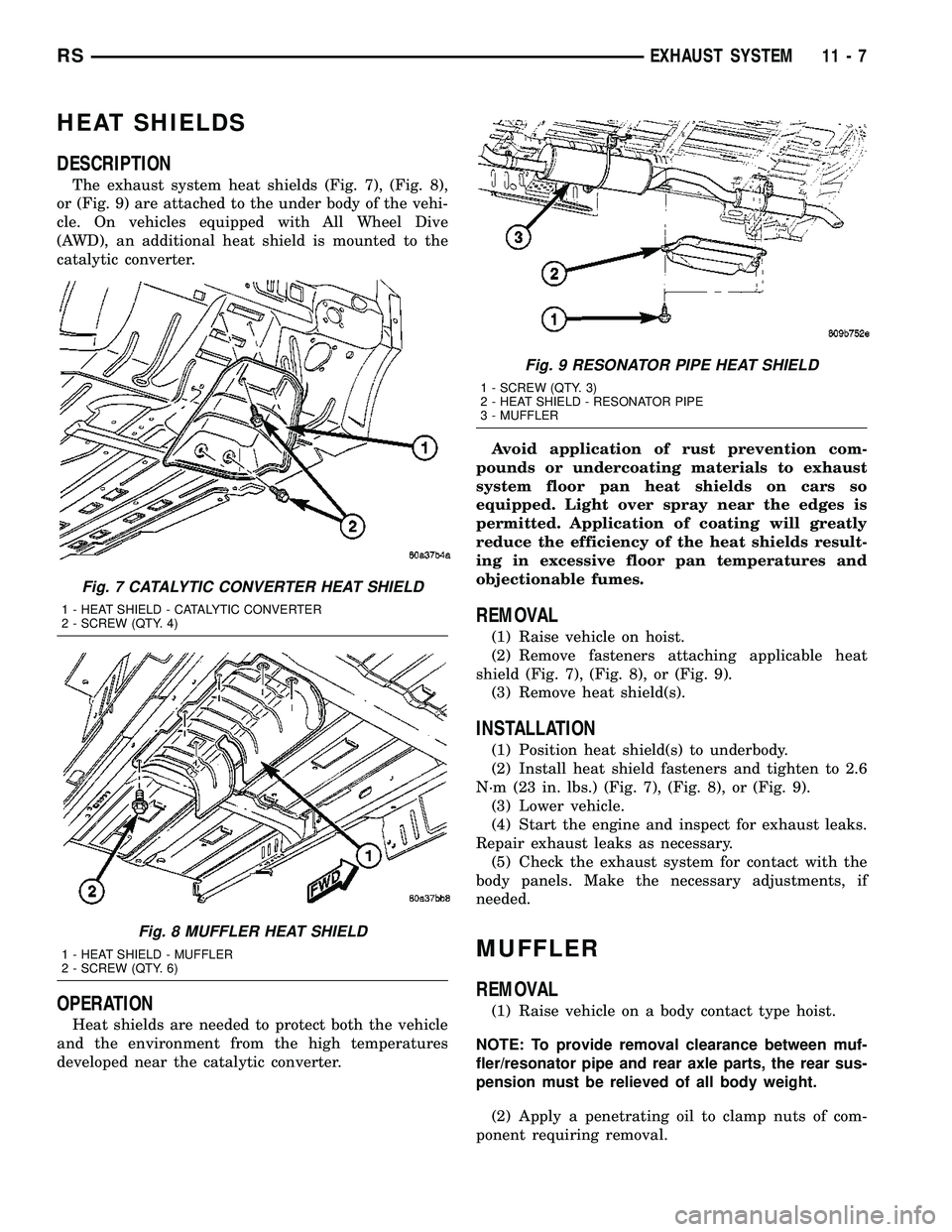
The exhaust system heat shields (Fig. 7), (Fig. 8),
or (Fig. 9) are attached to the under body of the vehi-
cle. On vehicles equipped with All Wheel Dive
(AWD), an additional heat shield is mounted to the
catalytic converter.
OPERATION
Heat shields are needed to protect both the vehicle
and the environment from the high temperatures
developed near the catalytic converter.Avoid application of rust prevention com-
pounds or undercoating materials to exhaust
system floor pan heat shields on cars so
equipped. Light over spray near the edges is
permitted. Application of coating will greatly
reduce the efficiency of the heat shields result-
ing in excessive floor pan temperatures and
objectionable fumes.
REMOVAL
(1) Raise vehicle on hoist.
(2) Remove fasteners attaching applicable heat
shield (Fig. 7), (Fig. 8), or (Fig. 9).
(3) Remove heat shield(s).
INSTALLATION
(1) Position heat shield(s) to underbody.
(2) Install heat shield fasteners and tighten to 2.6
N´m (23 in. lbs.) (Fig. 7), (Fig. 8), or (Fig. 9).
(3) Lower vehicle.
(4) Start the engine and inspect for exhaust leaks.
Repair exhaust leaks as necessary.
(5) Check the exhaust system for contact with the
body panels. Make the necessary adjustments, if
needed.
MUFFLER
REMOVAL
(1) Raise vehicle on a body contact type hoist.
NOTE: To provide removal clearance between muf-
fler/resonator pipe and rear axle parts, the rear sus-
pension must be relieved of all body weight.
(2) Apply a penetrating oil to clamp nuts of com-
ponent requiring removal.
Fig. 7 CATALYTIC CONVERTER HEAT SHIELD
1 - HEAT SHIELD - CATALYTIC CONVERTER
2 - SCREW (QTY. 4)
Fig. 8 MUFFLER HEAT SHIELD
1 - HEAT SHIELD - MUFFLER
2 - SCREW (QTY. 6)
Fig. 9 RESONATOR PIPE HEAT SHIELD
1 - SCREW (QTY. 3)
2 - HEAT SHIELD - RESONATOR PIPE
3 - MUFFLER
RSEXHAUST SYSTEM11-7
Page 1373 of 2339
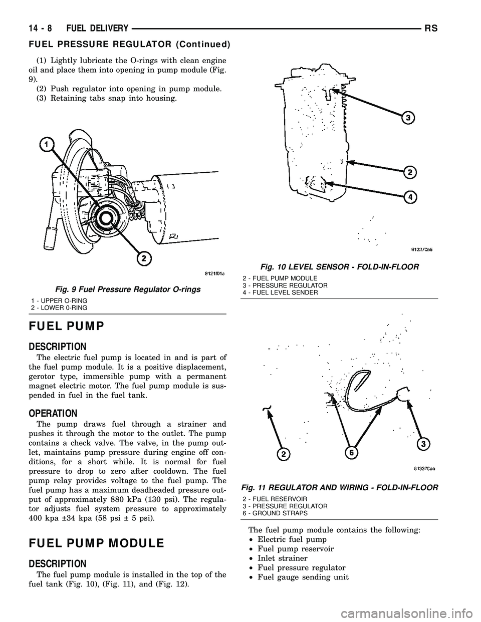
(1) Lightly lubricate the O-rings with clean engine
oil and place them into opening in pump module (Fig.
9).
(2) Push regulator into opening in pump module.
(3) Retaining tabs snap into housing.
FUEL PUMP
DESCRIPTION
The electric fuel pump is located in and is part of
the fuel pump module. It is a positive displacement,
gerotor type, immersible pump with a permanent
magnet electric motor. The fuel pump module is sus-
pended in fuel in the fuel tank.
OPERATION
The pump draws fuel through a strainer and
pushes it through the motor to the outlet. The pump
contains a check valve. The valve, in the pump out-
let, maintains pump pressure during engine off con-
ditions, for a short while. It is normal for fuel
pressure to drop to zero after cooldown. The fuel
pump relay provides voltage to the fuel pump. The
fuel pump has a maximum deadheaded pressure out-
put of approximately 880 kPa (130 psi). The regula-
tor adjusts fuel system pressure to approximately
400 kpa 34 kpa (58 psi 5 psi).
FUEL PUMP MODULE
DESCRIPTION
The fuel pump module is installed in the top of the
fuel tank (Fig. 10), (Fig. 11), and (Fig. 12).The fuel pump module contains the following:
²Electric fuel pump
²Fuel pump reservoir
²Inlet strainer
²Fuel pressure regulator
²Fuel gauge sending unit
Fig. 9 Fuel Pressure Regulator O-rings
1 - UPPER O-RING
2 - LOWER 0-RING
Fig. 10 LEVEL SENSOR - FOLD-IN-FLOOR
2 - FUEL PUMP MODULE
3 - PRESSURE REGULATOR
4 - FUEL LEVEL SENDER
Fig. 11 REGULATOR AND WIRING - FOLD-IN-FLOOR
2 - FUEL RESERVOIR
3 - PRESSURE REGULATOR
6 - GROUND STRAPS
14 - 8 FUEL DELIVERYRS
FUEL PRESSURE REGULATOR (Continued)