2005 CHRYSLER VOYAGER braking
[x] Cancel search: brakingPage 210 of 2339
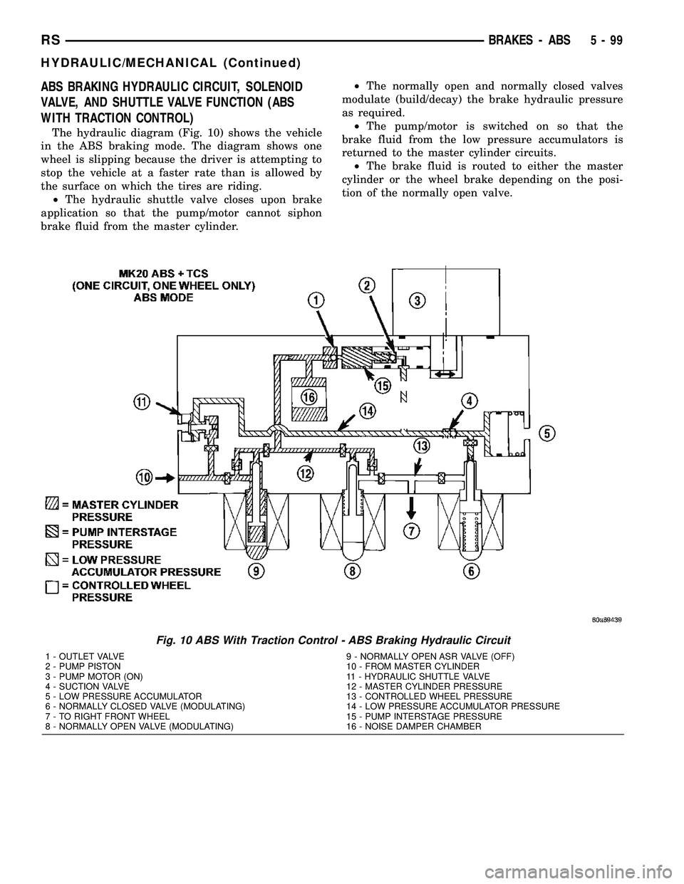
ABS BRAKING HYDRAULIC CIRCUIT, SOLENOID
VALVE, AND SHUTTLE VALVE FUNCTION (ABS
WITH TRACTION CONTROL)
The hydraulic diagram (Fig. 10) shows the vehicle
in the ABS braking mode. The diagram shows one
wheel is slipping because the driver is attempting to
stop the vehicle at a faster rate than is allowed by
the surface on which the tires are riding.
²The hydraulic shuttle valve closes upon brake
application so that the pump/motor cannot siphon
brake fluid from the master cylinder.²The normally open and normally closed valves
modulate (build/decay) the brake hydraulic pressure
as required.
²The pump/motor is switched on so that the
brake fluid from the low pressure accumulators is
returned to the master cylinder circuits.
²The brake fluid is routed to either the master
cylinder or the wheel brake depending on the posi-
tion of the normally open valve.
Fig. 10 ABS With Traction Control - ABS Braking Hydraulic Circuit
1 - OUTLET VALVE
2 - PUMP PISTON
3 - PUMP MOTOR (ON)
4 - SUCTION VALVE
5 - LOW PRESSURE ACCUMULATOR
6 - NORMALLY CLOSED VALVE (MODULATING)
7 - TO RIGHT FRONT WHEEL
8 - NORMALLY OPEN VALVE (MODULATING)9 - NORMALLY OPEN ASR VALVE (OFF)
10 - FROM MASTER CYLINDER
11 - HYDRAULIC SHUTTLE VALVE
12 - MASTER CYLINDER PRESSURE
13 - CONTROLLED WHEEL PRESSURE
14 - LOW PRESSURE ACCUMULATOR PRESSURE
15 - PUMP INTERSTAGE PRESSURE
16 - NOISE DAMPER CHAMBER
RSBRAKES - ABS5-99
HYDRAULIC/MECHANICAL (Continued)
Page 211 of 2339
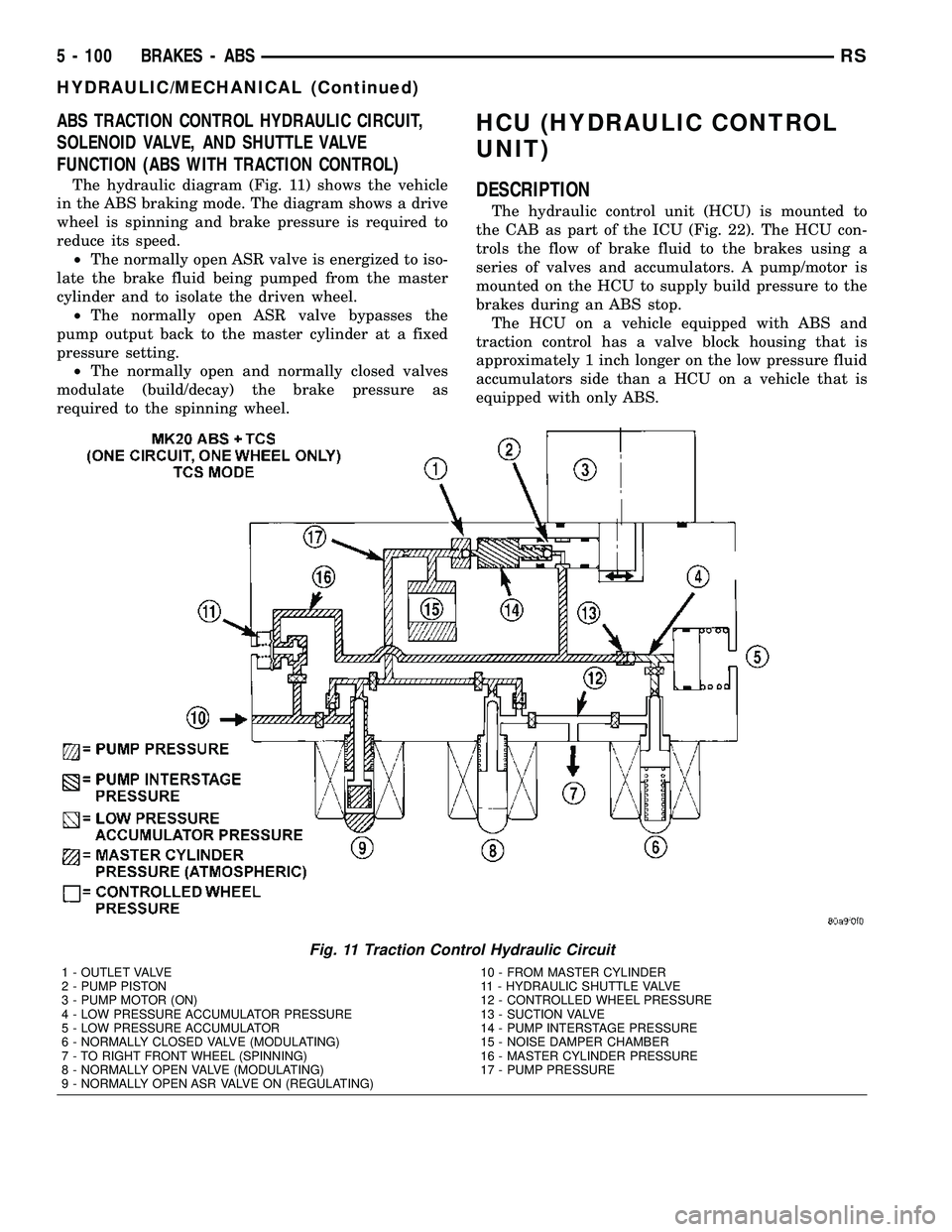
ABS TRACTION CONTROL HYDRAULIC CIRCUIT,
SOLENOID VALVE, AND SHUTTLE VALVE
FUNCTION (ABS WITH TRACTION CONTROL)
The hydraulic diagram (Fig. 11) shows the vehicle
in the ABS braking mode. The diagram shows a drive
wheel is spinning and brake pressure is required to
reduce its speed.
²The normally open ASR valve is energized to iso-
late the brake fluid being pumped from the master
cylinder and to isolate the driven wheel.
²The normally open ASR valve bypasses the
pump output back to the master cylinder at a fixed
pressure setting.
²The normally open and normally closed valves
modulate (build/decay) the brake pressure as
required to the spinning wheel.
HCU (HYDRAULIC CONTROL
UNIT)
DESCRIPTION
The hydraulic control unit (HCU) is mounted to
the CAB as part of the ICU (Fig. 22). The HCU con-
trols the flow of brake fluid to the brakes using a
series of valves and accumulators. A pump/motor is
mounted on the HCU to supply build pressure to the
brakes during an ABS stop.
The HCU on a vehicle equipped with ABS and
traction control has a valve block housing that is
approximately 1 inch longer on the low pressure fluid
accumulators side than a HCU on a vehicle that is
equipped with only ABS.
Fig. 11 Traction Control Hydraulic Circuit
1 - OUTLET VALVE
2 - PUMP PISTON
3 - PUMP MOTOR (ON)
4 - LOW PRESSURE ACCUMULATOR PRESSURE
5 - LOW PRESSURE ACCUMULATOR
6 - NORMALLY CLOSED VALVE (MODULATING)
7 - TO RIGHT FRONT WHEEL (SPINNING)
8 - NORMALLY OPEN VALVE (MODULATING)
9 - NORMALLY OPEN ASR VALVE ON (REGULATING)10 - FROM MASTER CYLINDER
11 - HYDRAULIC SHUTTLE VALVE
12 - CONTROLLED WHEEL PRESSURE
13 - SUCTION VALVE
14 - PUMP INTERSTAGE PRESSURE
15 - NOISE DAMPER CHAMBER
16 - MASTER CYLINDER PRESSURE
17 - PUMP PRESSURE
5 - 100 BRAKES - ABSRS
HYDRAULIC/MECHANICAL (Continued)
Page 212 of 2339
For more information, (Refer to 5 - BRAKES/HY-
DRAULIC/MECHANICAL/ICU (INTEGRATED CON-
TROL UNIT) - DESCRIPTION)
OPERATION
For information on the operation of the HCU as a
whole, refer to Hydraulic Circuits And Valve Opera-
tion which can be found elsewhere in this section.
For information on the operation of the components
within the HCU, refer to the following three topics.
VALVES AND SOLENOIDS
The valve block contains four inlet valves and four
outlet valves. The inlet valves are spring-loaded in
the open position and the outlet valves are spring-
loaded in the closed position during normal braking.
The fluid is allowed to flow from the master cylinder
to the wheel brakes.
During an ABS stop, these valves cycle to maintain
the proper slip ratio for each wheel. The inlet valve
closes preventing further pressure increase and the
outlet valve opens to provide a path from the wheel
brake to the HCU accumulators and pump/motor.
This releases (decays) pressure from the wheel brake,
thus releasing the wheel from excessive slippage.
Once the wheel is no longer slipping, the outlet valve
is closed and the inlet valve is opened to reapply
(build) pressure.
On vehicles with traction control, there is an extra
set of valves and solenoids. The ASR valves, mounted
in the HCU valve block, are normally in the open
position and close only when the traction control is
applied.
These isolator valves are used to isolate the rear
(non-driving) wheels of the vehicle from the hydraulic
pressure that the HCU pump/motor is sending to the
front (driving) wheels when traction control is being
applied. The rear brakes need to be isolated from the
master cylinder when traction control is being
applied so the rear wheels do not drag. For more
information, refer to Traction Control System in this
section.
BRAKE FLUID ACCUMULATORS
There are two fluid accumulators in the HCU±one
for the primary hydraulic circuit and one for the sec-
ondary hydraulic circuit. Each hydraulic circuit uses
a 5 cc accumulator.
The fluid accumulators temporarily store brake
fluid that is removed from the wheel brakes during
an ABS cycle. This stored fluid is used by the pump/
motor to provide build pressure for the brake hydrau-
lic system. When the antilock stop is complete, the
accumulators are drained by the pump/motor.
On ABS-only vehicles, there is a mini-accumulator
on the secondary hydraulic circuit that protects the
master cylinder seals during an ABS stop, and there
is a noise dampening chamber on the primary circuit.
On ABS with traction control vehicles, there are
two noise dampening chambers in the HCU.
PUMP/MOTOR
There are two pump assemblies in the HCUÐone
for the primary hydraulic circuit and one for the sec-
ondary hydraulic circuit. Both pumps are driven by a
common electric motor. This DC-type motor is inte-
gral to the HCU and is controlled by the CAB.
The pump/motor provides the extra amount of
brake fluid needed during antilock braking. Brake
fluid is released to the accumulators when the outlet
valve is opened during an antilock stop. The pump
mechanism consists of two opposing pistons operated
by an eccentric camshaft. In operation, one piston
draws fluid from the accumulators, and the opposing
piston pumps fluid to the master cylinder circuits.
When the antilock stop is complete, the pump/motor
drains the accumulators.
The CAB may turn on the pump/motor when an
antilock stop is detected. The pump/motor continues
to run during the antilock stop and is turned off after
the stop is complete. Under some conditions, the
pump/motor runs to drain the accumulators during
the next drive-off.
The pump/motor is not a serviceable item; if it
requires replacement, the HCU must be replaced.
RSBRAKES - ABS5 - 101
HCU (HYDRAULIC CONTROL UNIT) (Continued)
Page 289 of 2339

FEATURE LEARNING KEY
THE BCM HAS ONE LIFTGATE INPUT LOCATED IN THE OVERHEAD CONSOLE.
POWER LOCKOUT SWITCH INPUT
THE BCM HAS ONE LOCKOUT SWITCH INPUT THAT WHEN ENABLED WILL DISABLE THE B-PILLAR
SLIDING DOOR SWITCHES FROM ACTIVATING EITHER SLIDING DOOR WHEN DEPRESSED.
PCI AUDIO SYSTEM PCI MESSAGE RECEIVED FROM MODULE
REMOTE RADIO CONTROLS REMOTE RADIO SWITCHES PRESENT
VEHICLE THEFT SECURITY SKREEM MESSAGE RECEIVED, VALID KEY
RECEIVED, & DIAGNOSTIC PID RECEIVED.
MEMORY SEAT AND MIRRORS MEMORY SEAT SWITCH PRESENT AND OR PCI
MESSAGE RECEIVED FROM MEMORY MODULE
ABS W/TRACTION CONTROL PCI MESSAGE RECEIVED FROM CAB
SENTRY KEY IMMOBILIZER SYSTEM PCI MESSAGE RECEIVED FROM SKIM OR VTSS
PRESENT
ADJUSTABLE PEDAL MODULE PCI MESSAGE RECEIVED FROM ADJUSTABLE
PEDAL MODULE (APM)
When replacing a BCM there are three modules
available:
²Base
²Midline
²RG - Export
The Midline controller is used on vehicles that
have Power Door Locks. If a vehicle is equipped with
the Vehicle Theft Security System, the Midline con-
troller becomes a Premium when the theft feature is
enabled.
CAUTION: Do not swap Body Control Modules
between vehicles or body controller's off the shelf.
The BCM has internal diagnostic capability that
assists in diagnosing the system error. When an
OPEN or a SHORT circuit exists, the diagnostic tool
can be used to read the BCM faults. The faults are
very descriptive in identifying the appropriate fea-
ture that has faulted.
The only two faults that the BCM logs that con-
clude the replacement of a BCM are faults;
²# 01 - Internal BCM failure (replace BCM)
²# 1F - J1850 Internal Hardware Failure (replace
BCM)
Otherwise the appropriate diagnostic procedures
for each of the features should be taken when the
BCM logs a fault.
REMOVAL
(1) Disconnect and isolate the battery negative
cable.
(2) Remove the lower instrument panel silencer.(3) Remove the knee blocker and reinforcement
(Refer to 23 - BODY/INSTRUMENT PANEL/KNEE
BLOCKER REINFORCEMENT - REMOVAL).
(4) Disconnect the five wire connectors from the
bottom of the Body Control Module (BCM).
(5) Move bulkhead wiring aside.
(6) Remove the screws holding the BCM to the
bulkhead.
(7) Remove the BCM from the mounting bracket.
INSTALLATION
(1) Install the BCM to the mounting bracket.
(2) Install the screws holding the BCM to the
bulkhead.
(3) Connect the five wire connectors to the bottom
of the Body Control Module (BCM).
(4) Install the knee blocker and reinforcement
(Refer to 23 - BODY/INSTRUMENT PANEL/KNEE
BLOCKER REINFORCEMENT - INSTALLATION).
(5) Install the lower instrument panel silencer.
(6) Connect the battery negative cable.
(7) Verify proper operation of BCM and its func-
tions.
CONTROLLER ANTILOCK
BRAKE
DESCRIPTION
The controller antilock brake (CAB) is a micropro-
cessor-based device which monitors the antilock
brake system (ABS) during normal braking and con-
trols it when the vehicle is in an ABS stop. The CAB
is mounted to the HCU as part of the integrated con-
trol unit (ICU) (Fig. 1). The CAB uses a 24-way elec-
8E - 4 ELECTRONIC CONTROL MODULESRS
BODY CONTROL MODULE (Continued)
Page 290 of 2339

trical connector on the vehicle wiring harness. The
power source for the CAB is through the ignition
switch in the RUN or ON position. The CAB is on
the PCI bus.
OPERATION
The primary functions of the controller antilock
brake (CAB) are to:
²Monitor the antilock brake system for proper
operation.
²Detect wheel locking or wheel slipping tenden-
cies by monitoring the speed of all four wheels of the
vehicle.
²Control fluid modulation to the wheel brakes
while the system is in an ABS mode.
²Store diagnostic information.
²Provide communication to the DRBIIItscan tool
while in diagnostic mode.
²Illuminate the amber ABS warning indicator
lamp.
²(With traction control only) Illuminate the TRAC
ON lamp in the message center on the instrument
panel when a traction control event occurs.
²(with traction control only) Illuminate the TRAC
OFF lamp when the amber ABS warning indicator
lamp illuminates.
The CAB constantly monitors the antilock brake
system for proper operation. If the CAB detects a
fault, it will turn on the amber ABS warning indica-
tor lamp and disable the antilock braking system.
The normal base braking system will remain opera-
tional.
NOTE: If the vehicle is equipped with traction con-
trol, the TRAC OFF lamp will illuminate anytime the
amber ABS warning indicator lamp illuminates.The CAB continuously monitors the speed of each
wheel through the signals generated by the wheel
speed sensors to determine if any wheel is beginning
to lock. When a wheel locking tendency is detected,
the CAB commands the CAB command coils to actu-
ate. The coils then open and close the valves in the
HCU that modulate brake fluid pressure in some or
all of the hydraulic circuits. The CAB continues to
control pressure in individual hydraulic circuits until
a locking tendency is no longer present.
The CAB contains a self-diagnostic program that
monitors the antilock brake system for system faults.
When a fault is detected, the amber ABS warning
indicator lamp is turned on and the fault diagnostic
trouble code (DTC) is then stored in a diagnostic pro-
gram memory. A latched fault will disable certain
system functionality for the current ignition cycle. An
unlatched fault will disable certain system function-
ality until the fault condition disappears. These
DTC's will remain in the CAB memory even after the
ignition has been turned off. The DTC's can be read
and cleared from the CAB memory by a technician
using the DRBIIItscan tool. If not cleared with a
DRBIIItscan tool, the fault occurrence and DTC will
be automatically cleared from the CAB memory after
the identical fault has not been seen during the next
3,500 miles. Drive-off may be required for the amber
ABS warning indicator lamp to go out on the next
ignition cycle.
CAB INPUTS
²Wheel speed sensors (four)
²Brake lamp switch
²Ignition switch
²System and pump voltage
²Ground
²Traction control switch (if equipped)
²Diagnostic communication (PCI)
CAB OUTPUTS
²Amber ABS warning indicator lamp actuation
(via BUS)
²Red BRAKE warning indicator lamp actuation
(via BUS)
²Instrument cluster (MIC) communication (PCI)
²Traction control lamps (if equipped)
²Diagnostic communication (PCI, via BUS)
REMOVAL
(1) Disconnect the battery cables.
(2) Remove the battery (Refer to 8 - ELECTRI-
CAL/BATTERY SYSTEM/BATTERY - REMOVAL).
(3) Disconnect the vacuum hose connector at the
tank built into the battery tray.
(4) Remove the screw securing the coolant filler
neck to the battery tray.
Fig. 1 Integrated Control Unit (ICU)
1 - PUMP/MOTOR
2 - HCU
3 - PUMP/MOTOR CONNECTOR
4 - CAB
RSELECTRONIC CONTROL MODULES8E-5
CONTROLLER ANTILOCK BRAKE (Continued)
Page 534 of 2339

OPERATION
The PCM on NGC vehicles first senses that the
speed control is set. If the set speed is exceeded by
more than 4 mph (6.5 km/hr) and the throttle is
closed, the PCM on NGC vehicles causes the trans-
axle to downshift to THIRD gear. After downshifting,
the automatic speed control resumes normal opera-
tion. To ensure that an upshift is appropriate after
the set speed is reached, the PCM on NGC vehicles
waits until the speed control system opens the throt-
tle at least 6 degrees before upshifting to OVER-
DRIVE again.
If the driver applies the brakes, canceling auto-
matic speed control operation with the transaxle still
in THIRD gear, the PCM on NGC vehicles maintains
this gear until the driver opens the throttle at least 6
degrees to avoid an inappropriate upshift. The
upshift is also delayed for 2.5 seconds after reaching
the 6 degrees throttle opening in anticipation that
the driver might open the throttle enough to require
THIRD gear. This will avoid unnecessary and dis-
turbing transmission cycling. If the automatic speed
control RESUME feature is used after braking, the
upshift is delayed until the set speed is achieved to
reduce cycling and provide better response.
DIAGNOSIS AND TESTING - ROAD TEST
Perform a vehicle road test to verify reports of
speed control system malfunction. The road test
should include attention to the speedometer. Speed-
ometer operation should be smooth and without flut-
ter at all speeds.Flutter in the speedometer indicates a problem
which might cause surging in the speed control sys-
tem. The cause of any speedometer problems should
be corrected before proceeding. Refer to the Instru-
ment Cluster for speedometer diagnosis.
If a road test verifies an inoperative system, and
the speedometer operates properly, check for:
²A Diagnostic Trouble Code (DTC). If a DTC
exists, conduct tests per the Powertrain Diagnostic
Procedures manual.
²A misadjusted brake (stop) lamp switch. This
could also cause an intermittent problem.
²Loose or corroded electrical connections at the
servo. Corrosion should be removed from electrical
terminals and a light coating of Mopar Multipurpose
Grease, or equivalent, applied.
²Leaking vacuum reservoir.
²Loose or leaking vacuum hoses or connections.
²Defective one-way vacuum check valve.
²Secure attachment at both ends of the speed
control servo cable.
²Smooth operation of throttle linkage and throttle
body air valve.
²Conduct electrical test at PCM.
²Failed speed control servo. Do the servo vacuum
test.
CAUTION: When test probing for voltage or conti-
nuity at electrical connectors, care must be taken
not to damage connector, terminals or seals. If
these components are damaged, intermittent or
complete system failure may occur.
SPECIFICATIONS - TORQUE
DESCRIPTION N´m Ft. Lbs. In. Lbs.
Servo Mounting Bracket
Nuts14 10.3 123.9
Servo Mounting Bracket
Bolts14 10.3 123.9
Servo Mounting Nuts 6.7 60
RSSPEED CONTROL8P-3
SPEED CONTROL (Continued)
Page 1389 of 2339
²All monitored components (refer to the Emission
section for On-Board Diagnostics).
The PCM compares the upstream and downstream
heated oxygen sensor inputs to measure catalytic
convertor efficiency. If the catalyst efficiency drops
below the minimum acceptable percentage, the PCM
stores a diagnostic trouble code in memory, after 2
trips.
During certain idle conditions, the PCM may enter
a variable idle speed strategy. During variable idle
speed strategy the PCM adjusts engine speed based
on the following inputs.
²A/C status
²Battery voltage
²Battery temperature or Calculated Battery Tem-
perature
²Engine coolant temperature
²Engine run time
²Inlet/Intake air temperature
²Vehicle mileage
ACCELERATION MODE
This is a CLOSED LOOP mode. The PCM recog-
nizes an abrupt increase in Throttle Position sensor
output voltage or MAP sensor output voltage as a
demand for increased engine output and vehicle
acceleration. The PCM increases injector pulse width
in response to increased fuel demand.
²Wide Open Throttle-open loop
DECELERATION MODE
This is a CLOSED LOOP mode. During decelera-
tion the following inputs are received by the PCM:
²A/C status
²Battery voltage
²Inlet/Intake air temperature
²Engine coolant temperature
²Crankshaft position (engine speed)
²Exhaust gas oxygen content (upstream heated
oxygen sensor)
²Knock sensor
²Manifold absolute pressure
²Throttle position sensor
²IAC motor (solenoid) control changes in response
to MAP sensor feedback
The PCM may receive a closed throttle input from
the Throttle Position Sensor (TPS) when it senses an
abrupt decrease in manifold pressure. This indicates
a hard deceleration (Open Loop). In response, the
PCM may momentarily turn off the injectors. This
helps improve fuel economy, emissions and engine
braking.
WIDE-OPEN-THROTTLE MODE
This is an OPEN LOOP mode. During wide-open-
throttle operation, the following inputs are used by
the PCM:
²Inlet/Intake air temperature
²Engine coolant temperature
²Engine speed
²Knock sensor
²Manifold absolute pressure
²Throttle position
When the PCM senses a wide-open-throttle condi-
tion through the Throttle Position Sensor (TPS) it de-
energizes the A/C compressor clutch relay. This
disables the air conditioning system and disables
EGR (if equipped).
The PCM adjusts injector pulse width to supply a
predetermined amount of additional fuel, based on
MAP and RPM.
IGNITION SWITCH OFF MODE
When the operator turns the ignition switch to the
OFF position, the following occurs:
²All outputs are turned off, unless 02 Heater
Monitor test is being run. Refer to the Emission sec-
tion for On-Board Diagnostics.
²No inputs are monitored except for the heated
oxygen sensors. The PCM monitors the heating ele-
ments in the oxygen sensors and then shuts down.
FUEL CORRECTION or ADAPTIVE MEMORIES
DESCRIPTION
In Open Loop, the PCM changes pulse width with-
out feedback from the O2 Sensors. Once the engine
warms up to approximately 30 to 35É F, the PCM
goes into closed loopShort Term Correctionand
utilizes feedback from the O2 Sensors. Closed loop
Long Term Adaptive Memoryis maintained above
170É to 190É F unless the PCM senses wide open
throttle. At that time the PCM returns to Open Loop
operation.
OPERATION
Short Term
The first fuel correction program that begins func-
tioning is the short term fuel correction. This system
corrects fuel delivery in direct proportion to the read-
ings from the Upstream O2 Sensor.
The PCM monitors the air/fuel ratio by using the
input voltage from the O2 Sensor. When the voltage
reaches its preset high or low limit, the PCM begins
to add or remove fuel until the sensor reaches its
switch point. The short term corrections then begin.
The PCM makes a series of quick changes in the
injector pulse-width until the O2 Sensor reaches its
14 - 24 FUEL INJECTIONRS
FUEL INJECTION (Continued)
Page 1781 of 2339
the vehicle should not enter the passenger or luggage
compartment. Moving sealing surfaces will not
always seal water tight under all conditions. At
times, side glass or door seals will allow water to
enter the passenger compartment during high pres-
sure washing or hard driving rain (severe) condi-
tions. Overcompensating on door or glass
adjustments to stop a water leak that occurs under
severe conditions can cause premature seal wear and
excessive closing or latching effort. After completing
a repair, water test vehicle to verify leak has stopped
before returning vehicle to use.
VISUAL INSPECTION BEFORE WATER LEAK TESTS
Verify that floor and body plugs are in place, body
drains are clear, and body components are properly
aligned and sealed. If component alignment or seal-
ing is necessary, refer to the appropriate section of
this group for proper procedures.
WATER LEAK TESTS
WARNING: DO NOT USE ELECTRIC SHOP LIGHTS
OR TOOLS IN WATER TEST AREA. PERSONAL
INJURY CAN RESULT.
When the conditions causing a water leak have
been determined, simulate the conditions as closely
as possible.
²If a leak occurs with the vehicle parked in a
steady light rain, flood the leak area with an open-
ended garden hose.
²If a leak occurs while driving at highway speeds
in a steady rain, test the leak area with a reasonable
velocity stream or fan spray of water. Direct the
spray in a direction comparable to actual conditions.
²If a leak occurs when the vehicle is parked on an
incline, hoist the end or side of the vehicle to simu-
late this condition. This method can be used when
the leak occurs when the vehicle accelerates, stops or
turns. If the leak occurs on acceleration, hoist the
front of the vehicle. If the leak occurs when braking,
hoist the back of the vehicle. If the leak occurs on left
turns, hoist the left side of the vehicle. If the leak
occurs on right turns, hoist the right side of the vehi-
cle. For hoisting recommendations (Refer to LUBRI-
CATION & MAINTENANCE/HOISTING -
STANDARD PROCEDURE).
WATER LEAK DETECTION
To detect a water leak point-of-entry, do a water
test and watch for water tracks or droplets forming
on the inside of the vehicle. If necessary, remove inte-
rior trim covers or panels to gain visual access to the
leak area. If the hose cannot be positioned without
being held, have someone help do the water test.Some water leaks must be tested for a considerable
length of time to become apparent. When a leak
appears, find the highest point of the water track or
drop. The highest point usually will show the point of
entry. After leak point has been found, repair the
leak and water test to verify that the leak has
stopped.
Locating the entry point of water that is leaking
into a cavity between panels can be difficult. The
trapped water may splash or run from the cavity,
often at a distance from the entry point. Most water
leaks of this type become apparent after accelerating,
stopping, turning, or when on an incline.
MIRROR INSPECTION METHOD
When a leak point area is visually obstructed, use
a suitable mirror to gain visual access. A mirror can
also be used to deflect light to a limited-access area
to assist in locating a leak point.
BRIGHT LIGHT LEAK TEST METHOD
Some water leaks in the luggage compartment can
be detected without water testing. Position the vehi-
cle in a brightly lit area. From inside the darkened
luggage compartment inspect around seals and body
seams. If necessary, have a helper direct a drop light
over the suspected leak areas around the luggage
compartment. If light is visible through a normally
sealed location, water could enter through the open-
ing.
PRESSURIZED LEAK TEST METHOD
When a water leak into the passenger compart-
ment cannot be detected by water testing, pressurize
the passenger compartment and soap test exterior of
the vehicle. To pressurize the passenger compart-
ment, close all doors and windows, start engine, and
set heater control to high blower in HEAT position. If
engine can not be started, connect a charger to the
battery to ensure adequate voltage to the blower.
With interior pressurized, apply dish detergent solu-
tion to suspected leak area on the exterior of the
vehicle. Apply detergent solution with spray device or
soft bristle brush. If soap bubbles occur at a body
seam, joint, seal or gasket, the leak entry point could
be at that location.
WIND NOISE
Wind noise is the result of most air leaks. Air leaks
can be caused by poor sealing, improper body compo-
nent alignment, body seam porosity, or missing plugs
in the engine compartment or door hinge pillar areas.
All body sealing points should be airtight in normal
driving conditions. Moving sealing surfaces will not
always seal airtight under all conditions. At times,
side glass or door seals will allow wind noise to be
23 - 2 BODYRS
BODY (Continued)