2005 CHRYSLER VOYAGER heating
[x] Cancel search: heatingPage 356 of 2339

(3) Install the center bezel onto the instrument
panel, (Refer to 23 - BODY/INSTRUMENT PANEL/
INSTRUMENT PANEL CENTER BEZEL - INSTAL-
LATION).
(4) Connect the battery negative cable.
HEATED SEAT ELEMENTS
DESCRIPTION
The heated seat system includes two seat heating
elements in each front seat, one for the seat cushion
and the other for the seat back. The two elements for
each seat that are connected in series with the
Heated Seat Module (HSM). The temperature sensor
is a Negative Temperature Coefficient (NTC) ther-
mistor. One temperature sensor is used for each seat,
and it is located on the seat cushion heating element
for all models.
The seat heating elements are attached to the seat
cushion cover trim and seat back cover trim units.
The heated seat elements and the temperature sen-
sor cannot be adjusted or repaired and, if faulty or
damaged, the seat element assembly must be
replaced, (Refer to 8 - ELECTRICAL/HEATED
SEATS/HEATED SEAT ELEMENT - REMOVAL).
OPERATION
The heated seat elements resist the flow of electri-
cal current. When battery current is passed through
the elements, the resistance of the elements to the
current flow is released in the form of heat. The tem-
perature sensor is a Negative Temperature Coeffi-
cient (NTC) thermistor. When the temperature of the
seat cushion cover rises, the resistance of the sensor
decreases. The heated seat module supplies a five-
volt signal to one side of each sensor, and monitors
the voltage drop through the sensor on a return cir-
cuit. The heated seat module uses this temperature
sensor input to monitor the temperature of the seat,
and regulates the current flow to the seat heating
elements accordingly.
DIAGNOSIS AND TESTING
HEATED SEAT ELEMENTS
The wire harness connectors for the seat cushion
and seat back heating elements are located under the
seat, at the heated seat module. Refer to the appro-
priate wiring information for complete circuit sche-
matic or connector pin-out information.
In order to access and test the heated seat ele-
ments it will be necessary to remove the appropriate
front seat retaining bolts and lay the seat rearward,
up against one of the rear seats. It is not necessary
to disconnect the seat electrical connectors, just use
care not to damage the attached wire harnesses
while testing.
NOTE: When checking heated seat elements for
continuity, be certain to move the heating element
being checked. Moving the element, such as sitting
in the seat will eliminate the possibility of an inter-
mittent open in the element which would only be
evident if the element was in a certain position.
Failure to check the element in various positions
could result in an incomplete test.
SEAT CUSHION ELEMENT
(1) From under the vehicle, remove the appropri-
ate seats four retaining nuts.
(2) From inside the vehicle, pull the seat up, off
the mounting studs and lay it back, up against one of
the rear seats.
(3) Locate the heated seat module, attached to the
bottom of the seat cushion pan. Remove the heated
seat module from the seat cushion pan. Do not dis-
connect the electrical connectors at this time.
(4) Locate and disconnect the green 4-way electri-
cal connector, connected to the heated seat module.
(5) Check for continuity between the two outboard
circuit cavities of the wire harness connector (Pins
Fig. 5 SWITCH RETAINING SCREWS
1 - HEATED SEAT SWITCH ASSEMBLY
2 - RETAINING SCREWS
RSHEATED SEAT SYSTEM8G-11
HEATED SEAT SWITCH (Continued)
Page 357 of 2339

1&4). There should be continuity. If OK, (Refer to 8 -
ELECTRICAL/ELECTRONIC CONTROL MOD-
ULES/MEMORY HEATED SEAT/MIRROR MOD-
ULE - DIAGNOSIS AND TESTING) for complete
system testing procedures. If not OK, install a
replacement heated seat cushion element, (Refer to 8
- ELECTRICAL/HEATED SEATS/HEATED SEAT
ELEMENT - INSTALLATION).
SEAT BACK ELEMENT
(1) From under the vehicle, remove the appropri-
ate seats four retaining nuts.
(2) From inside the vehicle, pull the seat up and
off the mounting studs and lay it back, up against
one of the rear seats.
(3) Locate the heated seat module, attached to the
bottom of the seat cushion pan. Remove the heated
seat module from the seat cushion pan. Do not dis-
connect the electrical connectors at this time.
(4) Locate and disconnect the gray 2-way electrical
connector, connected to the heated seat module.
(5) Check for continuity between the two circuit
cavities of the 2-way wire harness connector. There
should be continuity. If OK, (Refer to 8 - ELECTRI-
CAL/ELECTRONIC CONTROL MODULES/MEM-
ORY HEATED SEAT/MIRROR MODULE -
DIAGNOSIS AND TESTING) for complete system
testing procedures. If not OK, install a replacement
heated seat back element, (Refer to 8 - ELECTRI-
CAL/HEATED SEATS/HEATED SEAT ELEMENT -
INSTALLATION).
REMOVAL
NOTE: Do not remove the factory installed heating
elements from the seat or seat back cushions. The
original element is permanently attached and can-
not be removed without permanent damage. The
replacement heating element is designed to be
applied directly on top of the factory installed heat-
ing element.
(1) Disconnect and isolate the battery negative
cable.
(2) Remove the appropriate seat cushion or seat
back trim cover.
(3) Disconnect the inoperative heated seat cushion
or seat back element electrical connectors (Fig. 6).
(4) Locate the wires leading from the inoperative
heating element and cut them off flush with the edge
of the original heating element.
INSTALLATION
(1) Peel off the adhesive backing on the back of the
replacement heating element and stick directly on
top of the factory installed heating element (Fig. 7).CAUTION: During the installation of the replace-
ment heating element, be careful not to fold or
crease the element assembly. Folds or creases will
cause premature failure.
Fig. 6 HEATING ELEMENT INSTALLED - TYPICAL
1 - SEAT BACK WIRE HARNESS
2 - HEATED SEAT WIRE HARNESS CONNECTOR
3 - HEATED SEAT CUSHION ELEMENT
Fig. 7 HEATING ELEMENT INSTALLATION
1 - ORIGINAL (INOPERATIVE) HEATING ELEMENT
2 - REPLACEMENT HEATING ELEMENT
8G - 12 HEATED SEAT SYSTEMRS
HEATED SEAT ELEMENTS (Continued)
Page 358 of 2339

(2) Connect the new heating element electrical
connectors (Fig. 8).Passenger seat shown, driver
seat similar.
(3) Connect the battery negative cable.
(4) Verify heated seat system operation.
(5) Install the appropriate seat cushion or seat
back trim cover.
NOTE: Make certain the seat wire harness is cor-
rectly routed through the seat and seat back. The
excess wire between the cushion and back ele-
ments should be securely tucked between the rear
of the cushion foam and the rear carpet flap of the
trim cover.HEATED SEAT SENSOR
DESCRIPTION
Two heated seat sensors are used per vehicle, one
in each front seat cushion heating element. The
heated seat temperature sensor is a Negative Tem-
perature Coefficient (NTC) thermistor.
The heated seat sensors cannot be repaired or
adjusted and if found to be faulty, the complete
heated seat cushion element must be replaced.
OPERATION
The temperature sensor is a Negative Temperature
Coefficient (NTC) thermistor. When the temperature
of the seat cushion cover rises, the resistance of the
sensor decreases. The heated seat module supplies a
five-volt current to one side of each sensor, and mon-
itors the voltage drop through the sensor on a return
circuit. The heated seat module uses this tempera-
ture sensor input to monitor the temperature of the
seat, and regulates the current flow to the seat heat-
ing elements accordingly.
DIAGNOSIS AND TESTING
HEATED SEAT SENSOR
Refer to the appropriate wiring information for
complete circuit schematic or connector pin-out infor-
mation.
(1) Disconnect and isolate the battery negative
cable. Disconnect the green 4-way heated seat mod-
ule wire harness connector.
(2) Using an ohmmeter, check the resistance
between cavities 2 and 3. The sensor resistance
should be between 50 kilohms at 15É C (60É F) and 2
kilohms at 30É C (85É F). If not OK, replace the
faulty seat element and sensor assembly.
Fig. 8 HEATED SEAT WIRE HARNESS ROUTING
1 - SEAT BACK HEATED SEAT WIRE HARNESS
2 - PASSENGER SEAT BACK
3 - SEAT BACK ELEMENT CONNECTOR
4 - SEAT CUSHION ELEMENT CONNECTOR
RSHEATED SEAT SYSTEM8G-13
HEATED SEAT ELEMENTS (Continued)
Page 449 of 2339

POWER MIRRORS
TABLE OF CONTENTS
page page
POWER MIRRORS
DESCRIPTION.........................26
OPERATION...........................26
DIAGNOSIS AND TESTING
POWER MIRRORS....................27
AUTOMATIC DAY / NIGHT MIRROR
DESCRIPTION.........................28
OPERATION...........................28
DIAGNOSIS AND TESTING
AUTOMATIC DAY / NIGHT MIRROR.......28
POWER FOLDAWAY MIRROR SWITCH -
EXPORT
DESCRIPTION.........................29OPERATION...........................29
REMOVAL.............................29
INSTALLATION.........................30
REMOTE SWITCH
DIAGNOSIS AND TESTING
REMOTE SWITCH.....................30
REMOVAL.............................30
INSTALLATION.........................30
SIDEVIEW MIRROR
REMOVAL.............................30
POWER MIRRORS
DESCRIPTION
If equipped with power mirrors, the control switch
is located on the instrument panel to the left of the
headlamp switch.
OPERATION
The power mirrors are connected to battery feed at
all times. Each mirror head contains two electric
motors, two drive mechanisms, an electric heating
element, and the mirror glass. If the vehicle is
equipped with the optional memory system, the
driver side mirror head also contains both a horizon-
tal and a vertical motor position sensor. One motor
and drive controls mirror up-and-down movement,
and the other controls right-and-left movement.An optional driver side outside electrochromic mir-
ror is able to automatically change its reflectance
level. This mirror is controlled by the circuitry of the
automatic day/night inside rear view mirror. A thin
layer of electrochromic material between two pieces
of conductive glass make up the face of the mirror.
Two photocell sensors on the inside rear view mirror
are used to monitor light levels and adjust the reflec-
tance of both the inside and driver side outside mir-
rors. This change in reflectance helps to reduce the
glare of headlamps approaching the vehicle from the
rear. (Refer to 8 - ELECTRICAL/POWER MIRRORS/
AUTOMATIC DAY / NIGHT MIRROR - DESCRIP-
TION) for more information on this system.
The motors which operate the mirrors are part of
the mirror assembly and cannot be serviced sepa-
rately.
8N - 26 POWER MIRRORSRS
Page 1190 of 2339

(9) Using a blade or suitable hose cutter, cut trans-
axle oil cooler lines off flush with fittings. Plug cooler
lines and fittings to prevent debris from entering
transaxle or cooler circuit. A service splice kit will be
installed upon reassembly.
(10) Disconnect transmission shift linkage and
electrical connectors.
(11) Disconnect throttle body linkage.
(12) Disconnect engine wiring harness.
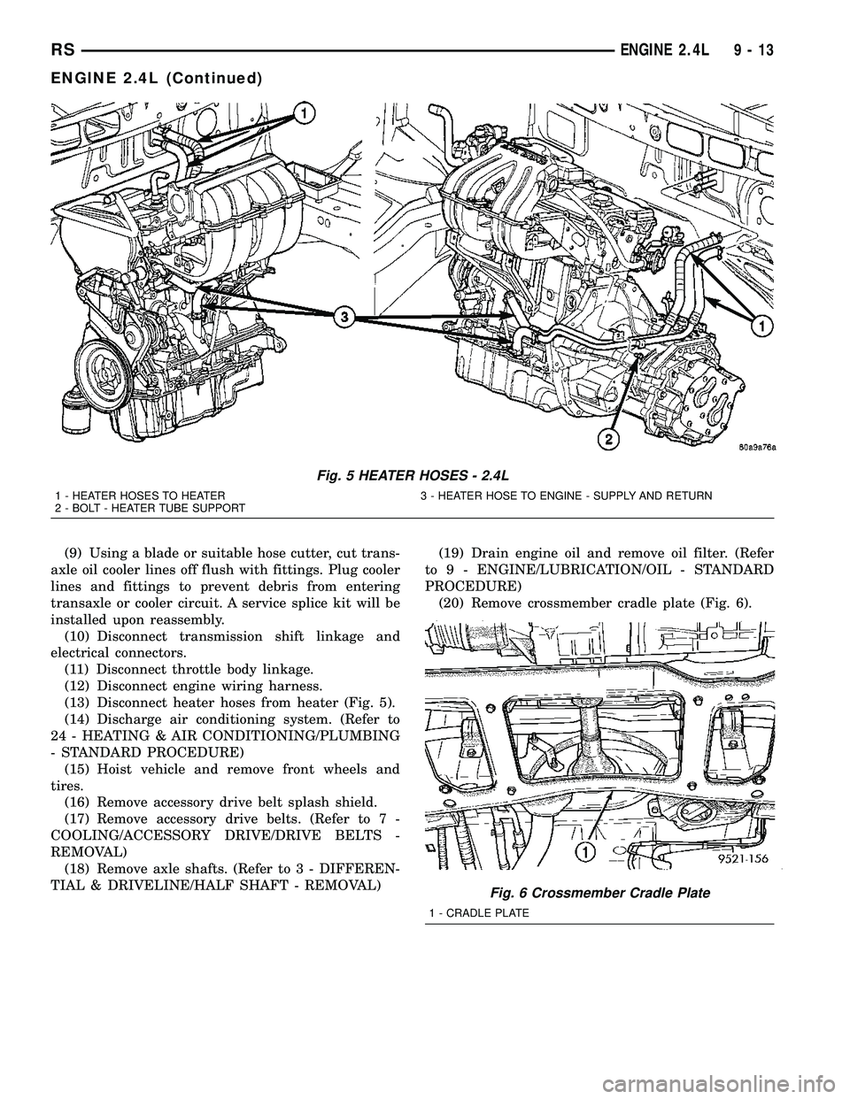
(13) Disconnect heater hoses from heater (Fig. 5).
(14) Discharge air conditioning system. (Refer to
24 - HEATING & AIR CONDITIONING/PLUMBING
- STANDARD PROCEDURE)
(15) Hoist vehicle and remove front wheels and
tires.
(16) Remove accessory drive belt splash shield.
(17) Remove accessory drive belts. (Refer to 7 -
COOLING/ACCESSORY DRIVE/DRIVE BELTS -
REMOVAL)
(18) Remove axle shafts. (Refer to 3 - DIFFEREN-
TIAL & DRIVELINE/HALF SHAFT - REMOVAL)(19) Drain engine oil and remove oil filter. (Refer
to 9 - ENGINE/LUBRICATION/OIL - STANDARD
PROCEDURE)
(20) Remove crossmember cradle plate (Fig. 6).
Fig. 5 HEATER HOSES - 2.4L
1 - HEATER HOSES TO HEATER 3 - HEATER HOSE TO ENGINE - SUPPLY AND RETURN
2 - BOLT - HEATER TUBE SUPPORT
Fig. 6 Crossmember Cradle Plate
1 - CRADLE PLATE
RSENGINE 2.4L9-13
ENGINE 2.4L (Continued)
Page 1202 of 2339

AIR CLEANER HOUSING
REMOVAL
(1) Disconnect the negative battery cable.
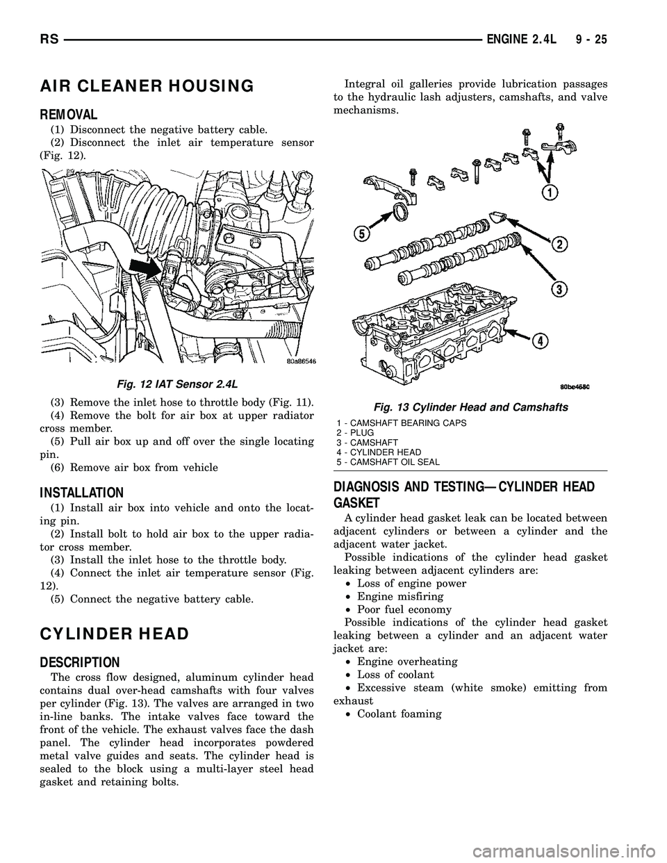
(2) Disconnect the inlet air temperature sensor
(Fig. 12).
(3) Remove the inlet hose to throttle body (Fig. 11).
(4) Remove the bolt for air box at upper radiator
cross member.
(5) Pull air box up and off over the single locating
pin.
(6) Remove air box from vehicle
INSTALLATION
(1) Install air box into vehicle and onto the locat-
ing pin.
(2) Install bolt to hold air box to the upper radia-
tor cross member.
(3) Install the inlet hose to the throttle body.
(4) Connect the inlet air temperature sensor (Fig.
12).
(5) Connect the negative battery cable.
CYLINDER HEAD
DESCRIPTION
The cross flow designed, aluminum cylinder head
contains dual over-head camshafts with four valves
per cylinder (Fig. 13). The valves are arranged in two
in-line banks. The intake valves face toward the
front of the vehicle. The exhaust valves face the dash
panel. The cylinder head incorporates powdered
metal valve guides and seats. The cylinder head is
sealed to the block using a multi-layer steel head
gasket and retaining bolts.Integral oil galleries provide lubrication passages
to the hydraulic lash adjusters, camshafts, and valve
mechanisms.
DIAGNOSIS AND TESTINGÐCYLINDER HEAD
GASKET
A cylinder head gasket leak can be located between
adjacent cylinders or between a cylinder and the
adjacent water jacket.
Possible indications of the cylinder head gasket
leaking between adjacent cylinders are:
²Loss of engine power
²Engine misfiring
²Poor fuel economy
Possible indications of the cylinder head gasket
leaking between a cylinder and an adjacent water
jacket are:
²Engine overheating
²Loss of coolant
²Excessive steam (white smoke) emitting from
exhaust
²Coolant foaming
Fig. 12 IAT Sensor 2.4L
Fig. 13 Cylinder Head and Camshafts
1 - CAMSHAFT BEARING CAPS
2 - PLUG
3 - CAMSHAFT
4 - CYLINDER HEAD
5 - CAMSHAFT OIL SEAL
RSENGINE 2.4L9-25
Page 1266 of 2339

(13) Disconnect the EGR transducer electrical con-
nector (if equipped).
(14) Disconnect the vacuum hoses from throttle
body.
(15) Disconnect the brake booster and speed con-
trol vacuum hoses.
(16) Disengage wire harness clip from the right
side engine mount.
(17) Remove the power steering reservoir from
mounting position and set aside.Do notdisconnect
hose.
(18) Disconnect ground strap from rear of cylinder
head.
(19) Disconnect engine coolant temperature (ECT)
sensor and ignition coil electrical connectors.
(20) Disconnect the fuel injector electrical harness
connector and disengage clip from support bracket.
(21) Disconnect camshaft and crankshaft position
sensor electrical connectors.
(22) Evacuate air conditioning system. Refer to 24
- HEATING & AIR CONDITIONING.
(23) Disconnect A/C compressor electrical connec-
tor.
(24) Disconnect the A/C lines from compressor.
Cover and seal all openings of hoses and compressor.
(25) Remove the radiator upper hose.
(26) Disengage electrical harness clip at transaxle
dipstick tube.
(27) Remove transaxle dipstick tube. Seal opening
using a suitable plug.
NOTE: When the transaxle cooler lines are removed
from the rolled-groove type fittings at the transaxle,
damage to the inner wall of the hose will occur. To
prevent prevent potential leakage, the cooler hoses
must be cut off flush at the transaxle fitting, and a
service cooler hose splice kit must be installed
upon reassembly.
(28) Using a blade or suitable hose cutter, cut
transaxle oil cooler lines off flush with fittings. Plug
cooler lines and fittings to prevent debris from enter-
ing transaxle or cooler circuit. A service splice kit will
be installed upon reassembly.
(29) Disconnect transaxle shift linkage and electri-
cal connectors.
(30) Raise vehicle on hoist and drain the engine
oil.
(31) Remove the axle shafts. (Refer to 3 - DIFFER-
ENTIAL & DRIVELINE/HALF SHAFT - REMOVAL)
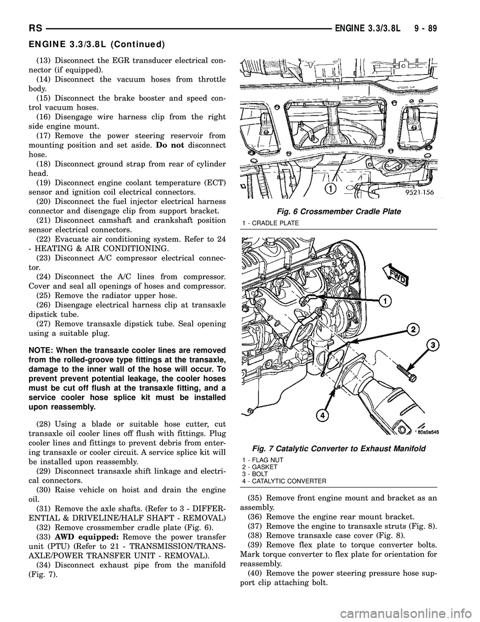
(32) Remove crossmember cradle plate (Fig. 6).
(33)AWD equipped:Remove the power transfer
unit (PTU) (Refer to 21 - TRANSMISSION/TRANS-
AXLE/POWER TRANSFER UNIT - REMOVAL).
(34) Disconnect exhaust pipe from the manifold
(Fig. 7).(35) Remove front engine mount and bracket as an
assembly.
(36) Remove the engine rear mount bracket.
(37) Remove the engine to transaxle struts (Fig. 8).
(38) Remove transaxle case cover (Fig. 8).
(39) Remove flex plate to torque converter bolts.
Mark torque converter to flex plate for orientation for
reassembly.
(40) Remove the power steering pressure hose sup-
port clip attaching bolt.
Fig. 6 Crossmember Cradle Plate
1 - CRADLE PLATE
Fig. 7 Catalytic Converter to Exhaust Manifold
1 - FLAG NUT
2 - GASKET
3 - BOLT
4 - CATALYTIC CONVERTER
RSENGINE 3.3/3.8L9-89
ENGINE 3.3/3.8L (Continued)
Page 1279 of 2339

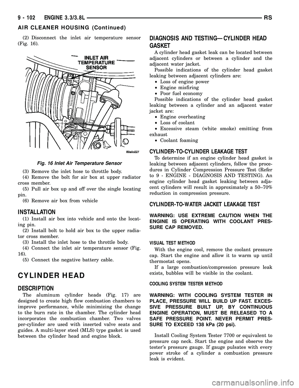
(2) Disconnect the inlet air temperature sensor
(Fig. 16).
(3) Remove the inlet hose to throttle body.
(4) Remove the bolt for air box at upper radiator
cross member.
(5) Pull air box up and off over the single locating
pin.
(6) Remove air box from vehicle
INSTALLATION
(1) Install air box into vehicle and onto the locat-
ing pin.
(2) Install bolt to hold air box to the upper radia-
tor cross member.
(3) Install the inlet hose to the throttle body.
(4) Connect the inlet air temperature sensor (Fig.
16).
(5) Connect the negative battery cable.
CYLINDER HEAD
DESCRIPTION
The aluminum cylinder heads (Fig. 17) are
designed to create high flow combustion chambers to
improve performance, while minimizing the change
to the burn rate in the chamber. The cylinder head
incorporates the combustion chamber. Two valves
per-cylinder are used with inserted valve seats and
guides. A multi-layer steel (MLS) type gasket is used
between the cylinder head and engine block.
DIAGNOSIS AND TESTINGÐCYLINDER HEAD
GASKET
A cylinder head gasket leak can be located between
adjacent cylinders or between a cylinder and the
adjacent water jacket.
Possible indications of the cylinder head gasket
leaking between adjacent cylinders are:
²Loss of engine power
²Engine misfiring
²Poor fuel economy
Possible indications of the cylinder head gasket
leaking between a cylinder and an adjacent water
jacket are:
²Engine overheating
²Loss of coolant
²Excessive steam (white smoke) emitting from
exhaust
²Coolant foaming
CYLINDER-TO-CYLINDER LEAKAGE TEST
To determine if an engine cylinder head gasket is
leaking between adjacent cylinders, follow the proce-
dures in Cylinder Compression Pressure Test (Refer
to 9 - ENGINE - DIAGNOSIS AND TESTING). An
engine cylinder head gasket leaking between adja-
cent cylinders will result in approximately a 50±70%
reduction in compression pressure.
CYLINDER-TO-WATER JACKET LEAKAGE TEST
WARNING: USE EXTREME CAUTION WHEN THE
ENGINE IS OPERATING WITH COOLANT PRES-
SURE CAP REMOVED.
VISUAL TEST METHOD
With the engine cool, remove the coolant pressure
cap. Start the engine and allow it to warm up until
thermostat opens.
If a large combustion/compression pressure leak
exists, bubbles will be visible in the coolant.
COOLING SYSTEM TESTER METHOD
WARNING: WITH COOLING SYSTEM TESTER IN
PLACE, PRESSURE WILL BUILD UP FAST. EXCES-
SIVE PRESSURE BUILT UP, BY CONTINUOUS
ENGINE OPERATION, MUST BE RELEASED TO A
SAFE PRESSURE POINT. NEVER PERMIT PRES-
SURE TO EXCEED 138 kPa (20 psi).
Install Cooling System Tester 7700 or equivalent to
pressure cap neck. Start the engine and observe the
tester's pressure gauge. If gauge pulsates with every
power stroke of a cylinder a combustion pressure
leak is evident.
Fig. 16 Inlet Air Temperature Sensor
9 - 102 ENGINE 3.3/3.8LRS
AIR CLEANER HOUSING (Continued)