2005 CHRYSLER VOYAGER brake
[x] Cancel search: brakePage 1238 of 2339
(9) Disconnect throttle and speed control (if
equipped) cables from throttle lever and bracket.
(Refer to 14 - FUEL SYSTEM/FUEL INJECTION/
THROTTLE CONTROL CABLE - REMOVAL)
(10) Remove the EGR tube. (Refer to 25 - EMIS-
SIONS CONTROL/EXHAUST GAS RECIRCULA-
TION/TUBE - REMOVAL)
(11) Remove the upper manifold support bracket
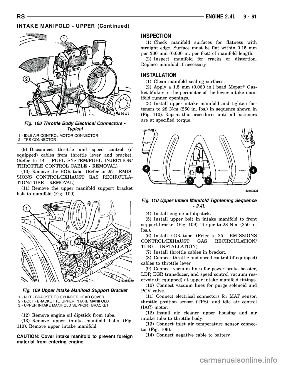
bolt to manifold (Fig. 109).
(12) Remove engine oil dipstick from tube.
(13) Remove upper intake manifold bolts (Fig.
110). Remove upper intake manifold.
CAUTION: Cover intake manifold to prevent foreign
material from entering engine.
INSPECTION
(1) Check manifold surfaces for flatness with
straight edge. Surface must be flat within 0.15 mm
per 300 mm (0.006 in. per foot) of manifold length.
(2) Inspect manifold for cracks or distortion.
Replace manifold if necessary.
INSTALLATION
(1) Clean manifold sealing surfaces.
(2) Apply a 1.5 mm (0.060 in.) bead MopartGas-
ket Maker to the perimeter of the lower intake man-
ifold runner openings.
(3) Install upper intake manifold and tighten fas-
teners to 28 N´m (250 in. lbs.) in sequence shown in
(Fig. 110). Repeat this procedures until all fasteners
are at specified torque.
(4) Install engine oil dipstick.
(5) Install upper bolt in intake manifold to front
support bracket (Fig. 109). Torque to 28 N´m (250 in.
lbs.).
(6) Install EGR tube. (Refer to 25 - EMISSIONS
CONTROL/EXHAUST GAS RECIRCULATION/
TUBE - INSTALLATION)
(7) Install throttle cables in bracket.
(8) Connect throttle and speed control (if equipped)
cables to throttle lever.
(9) Connect vacuum lines for power brake booster,
LDP, EGR transducer, and speed control vacuum res-
ervoir (if equipped) at upper intake manifold fittings.
(10) Connect vacuum lines for purge solenoid and
PCV valve.
(11) Connect electrical connectors for MAP sensor,
throttle position sensor (TPS), and idle air control
(IAC) motor.
(12) Install air cleaner upper housing and air
intake tube to throttle body.
(13) Connect inlet air temperature sensor connec-
tor (Fig. 106).
(14) Connect negative cable to battery.
Fig. 108 Throttle Body Electrical Connectors -
Typical
1 - IDLE AIR CONTROL MOTOR CONNECTOR
2 - TPS CONNECTOR
Fig. 109 Upper Intake Manifold Support Bracket
1 - NUT - BRACKET TO CYLINDER HEAD COVER
2 - BOLT - BRACKET TO UPPER INTAKE MANIFOLD
3 - UPPER INTAKE MANIFOLD SUPPORT BRACKET
Fig. 110 Upper Intake Manifold Tightening Sequence
- 2.4L
RSENGINE 2.4L9-61
INTAKE MANIFOLD - UPPER (Continued)
Page 1266 of 2339
(13) Disconnect the EGR transducer electrical con-
nector (if equipped).
(14) Disconnect the vacuum hoses from throttle
body.
(15) Disconnect the brake booster and speed con-
trol vacuum hoses.
(16) Disengage wire harness clip from the right
side engine mount.
(17) Remove the power steering reservoir from
mounting position and set aside.Do notdisconnect
hose.
(18) Disconnect ground strap from rear of cylinder
head.
(19) Disconnect engine coolant temperature (ECT)
sensor and ignition coil electrical connectors.
(20) Disconnect the fuel injector electrical harness
connector and disengage clip from support bracket.
(21) Disconnect camshaft and crankshaft position
sensor electrical connectors.
(22) Evacuate air conditioning system. Refer to 24
- HEATING & AIR CONDITIONING.
(23) Disconnect A/C compressor electrical connec-
tor.
(24) Disconnect the A/C lines from compressor.
Cover and seal all openings of hoses and compressor.
(25) Remove the radiator upper hose.
(26) Disengage electrical harness clip at transaxle
dipstick tube.
(27) Remove transaxle dipstick tube. Seal opening
using a suitable plug.
NOTE: When the transaxle cooler lines are removed
from the rolled-groove type fittings at the transaxle,
damage to the inner wall of the hose will occur. To
prevent prevent potential leakage, the cooler hoses
must be cut off flush at the transaxle fitting, and a
service cooler hose splice kit must be installed
upon reassembly.
(28) Using a blade or suitable hose cutter, cut
transaxle oil cooler lines off flush with fittings. Plug
cooler lines and fittings to prevent debris from enter-
ing transaxle or cooler circuit. A service splice kit will
be installed upon reassembly.
(29) Disconnect transaxle shift linkage and electri-
cal connectors.
(30) Raise vehicle on hoist and drain the engine
oil.
(31) Remove the axle shafts. (Refer to 3 - DIFFER-
ENTIAL & DRIVELINE/HALF SHAFT - REMOVAL)
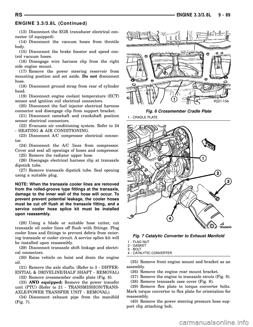
(32) Remove crossmember cradle plate (Fig. 6).
(33)AWD equipped:Remove the power transfer
unit (PTU) (Refer to 21 - TRANSMISSION/TRANS-
AXLE/POWER TRANSFER UNIT - REMOVAL).
(34) Disconnect exhaust pipe from the manifold
(Fig. 7).(35) Remove front engine mount and bracket as an
assembly.
(36) Remove the engine rear mount bracket.
(37) Remove the engine to transaxle struts (Fig. 8).
(38) Remove transaxle case cover (Fig. 8).
(39) Remove flex plate to torque converter bolts.
Mark torque converter to flex plate for orientation for
reassembly.
(40) Remove the power steering pressure hose sup-
port clip attaching bolt.
Fig. 6 Crossmember Cradle Plate
1 - CRADLE PLATE
Fig. 7 Catalytic Converter to Exhaust Manifold
1 - FLAG NUT
2 - GASKET
3 - BOLT
4 - CATALYTIC CONVERTER
RSENGINE 3.3/3.8L9-89
ENGINE 3.3/3.8L (Continued)
Page 1269 of 2339
(9) Raise vehicle.
(10) Attach wiring harness support clip to the
engine oil dipstick tube.
(11) Connect oil pressure switch electrical connec-
tor.
(12) Install the A/C compressor.
(13) Install the water pump pulley.
(14) Connect the radiator lower hose.
(15) Install the accessory drive belt and splash
shield (Refer to 7 - COOLING/ACCESSORY DRIVE/
DRIVE BELTS - INSTALLATION).(16) Connect the engine block heater electrical con-
nector (if equipped).
(17) Connect the knock sensor electrical connector
(3.8L only).
(18) Install the torque converter to flex plate bolts.
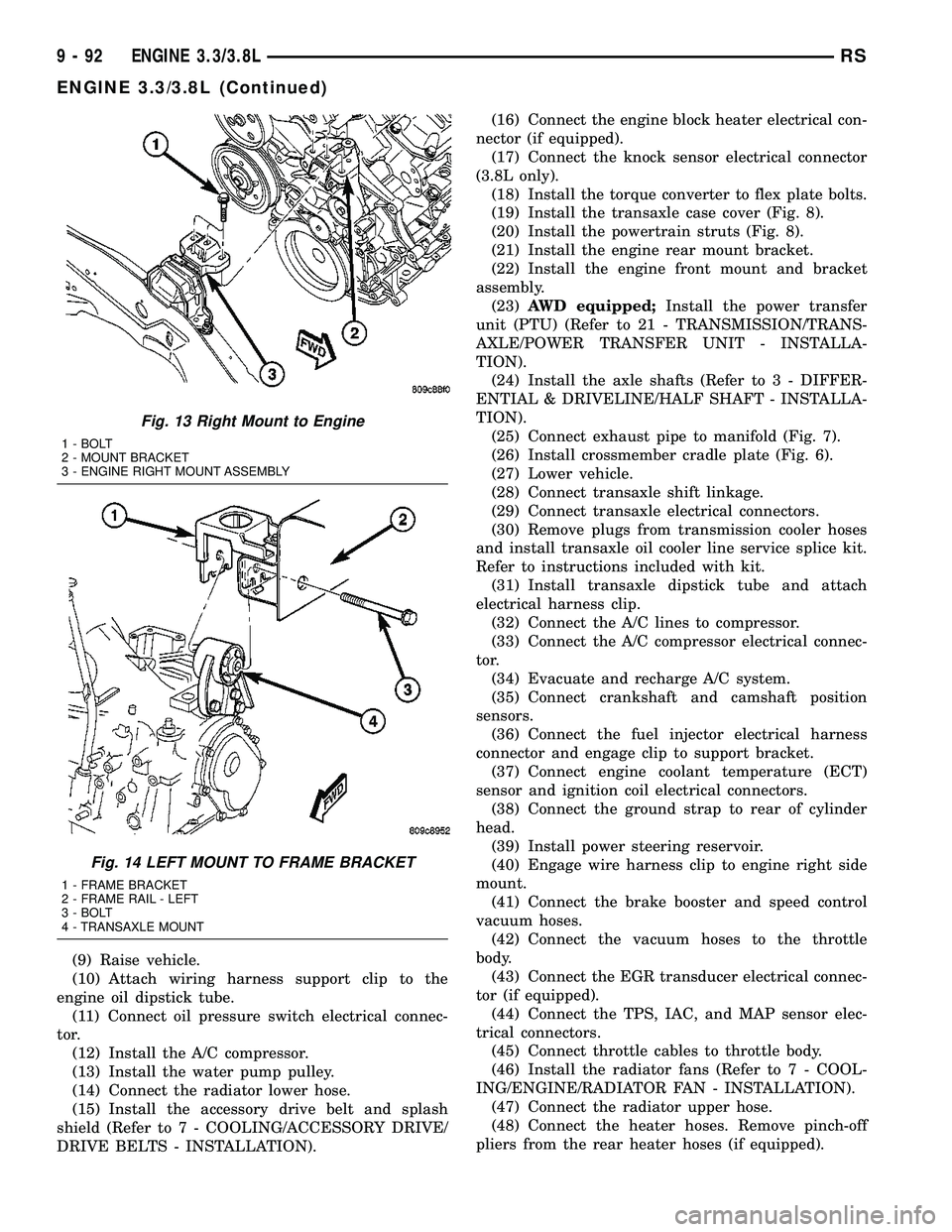
(19) Install the transaxle case cover (Fig. 8).
(20) Install the powertrain struts (Fig. 8).
(21) Install the engine rear mount bracket.
(22) Install the engine front mount and bracket
assembly.
(23)AWD equipped;Install the power transfer
unit (PTU) (Refer to 21 - TRANSMISSION/TRANS-
AXLE/POWER TRANSFER UNIT - INSTALLA-
TION).
(24) Install the axle shafts (Refer to 3 - DIFFER-
ENTIAL & DRIVELINE/HALF SHAFT - INSTALLA-
TION).
(25) Connect exhaust pipe to manifold (Fig. 7).
(26) Install crossmember cradle plate (Fig. 6).
(27) Lower vehicle.
(28) Connect transaxle shift linkage.
(29) Connect transaxle electrical connectors.
(30) Remove plugs from transmission cooler hoses
and install transaxle oil cooler line service splice kit.
Refer to instructions included with kit.
(31) Install transaxle dipstick tube and attach
electrical harness clip.
(32) Connect the A/C lines to compressor.
(33) Connect the A/C compressor electrical connec-
tor.
(34) Evacuate and recharge A/C system.
(35) Connect crankshaft and camshaft position
sensors.
(36) Connect the fuel injector electrical harness
connector and engage clip to support bracket.
(37) Connect engine coolant temperature (ECT)
sensor and ignition coil electrical connectors.
(38) Connect the ground strap to rear of cylinder
head.
(39) Install power steering reservoir.
(40) Engage wire harness clip to engine right side
mount.
(41) Connect the brake booster and speed control
vacuum hoses.
(42) Connect the vacuum hoses to the throttle
body.
(43) Connect the EGR transducer electrical connec-
tor (if equipped).
(44) Connect the TPS, IAC, and MAP sensor elec-
trical connectors.
(45) Connect throttle cables to throttle body.
(46) Install the radiator fans (Refer to 7 - COOL-
ING/ENGINE/RADIATOR FAN - INSTALLATION).
(47) Connect the radiator upper hose.
(48) Connect the heater hoses. Remove pinch-off
pliers from the rear heater hoses (if equipped).
Fig. 13 Right Mount to Engine
1 - BOLT
2 - MOUNT BRACKET
3 - ENGINE RIGHT MOUNT ASSEMBLY
Fig. 14 LEFT MOUNT TO FRAME BRACKET
1 - FRAME BRACKET
2 - FRAME RAIL - LEFT
3 - BOLT
4 - TRANSAXLE MOUNT
9 - 92 ENGINE 3.3/3.8LRS
ENGINE 3.3/3.8L (Continued)
Page 1325 of 2339
STANDARD PROCEDURE - INTAKE MANIFOLD
VACUUM PORT REPAIR
The composite intake manifold vacuum ports can
be repaired. Although, if the manifold plenum cham-
ber is damaged or cracked, the manifold must be
replaced.
To repair a broken or damaged vacuum nipple
(port) on the composite intake manifold, perform the
following procedure:
PARTS REQUIRED TOOLS REQUIRED
´ Brass Nipple ± 1/49
O.D. x 1/89pipe thread
(LDP/Speed Control Port)´ Pipe Tap ± 1/89-18
NPT
´ Drill Bit ± 11/329
´ File/Sandpaper
´ Brass Nipple ± 1/29
O.D. x 1/49pipe thread
(Brake Booster Port)´ Pipe Tap ± 1/49-18
NPT
´ Drill Bit ± 7/169
´ File/Sandpaper
NOTE: While performing this procedure, avoid get-
ting the manifold material residue into the plenum
chamber.
(1) File or sand the remaining port back until a
flat surface is obtained (plane normal to nipple (port)
axis).
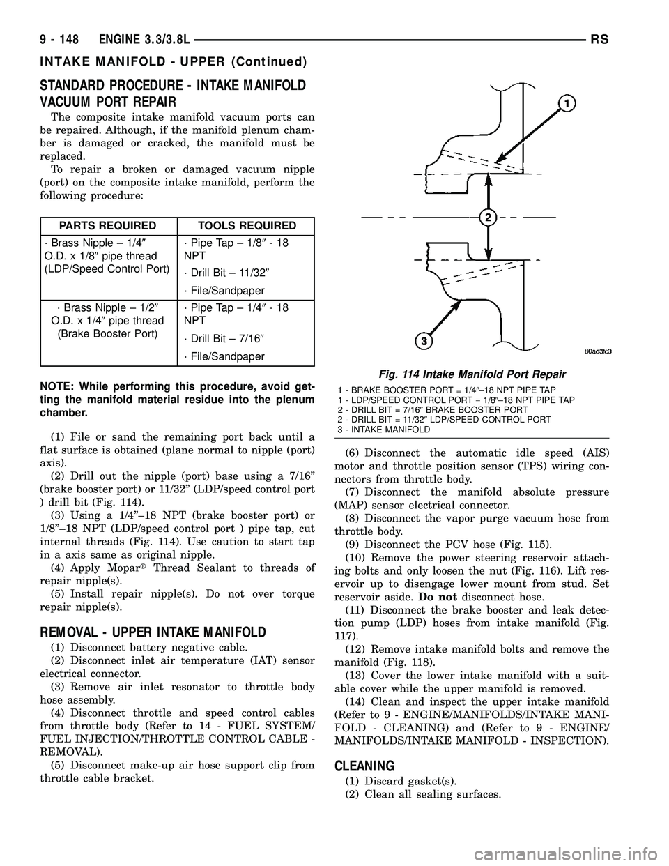
(2) Drill out the nipple (port) base using a 7/16º
(brake booster port) or 11/32º (LDP/speed control port
) drill bit (Fig. 114).
(3) Using a 1/4º±18 NPT (brake booster port) or
1/8º±18 NPT (LDP/speed control port ) pipe tap, cut
internal threads (Fig. 114). Use caution to start tap
in a axis same as original nipple.
(4) Apply MopartThread Sealant to threads of
repair nipple(s).
(5) Install repair nipple(s). Do not over torque
repair nipple(s).
REMOVAL - UPPER INTAKE MANIFOLD
(1) Disconnect battery negative cable.
(2) Disconnect inlet air temperature (IAT) sensor
electrical connector.
(3) Remove air inlet resonator to throttle body
hose assembly.
(4) Disconnect throttle and speed control cables
from throttle body (Refer to 14 - FUEL SYSTEM/
FUEL INJECTION/THROTTLE CONTROL CABLE -
REMOVAL).
(5) Disconnect make-up air hose support clip from
throttle cable bracket.(6) Disconnect the automatic idle speed (AIS)
motor and throttle position sensor (TPS) wiring con-
nectors from throttle body.
(7) Disconnect the manifold absolute pressure
(MAP) sensor electrical connector.
(8) Disconnect the vapor purge vacuum hose from
throttle body.
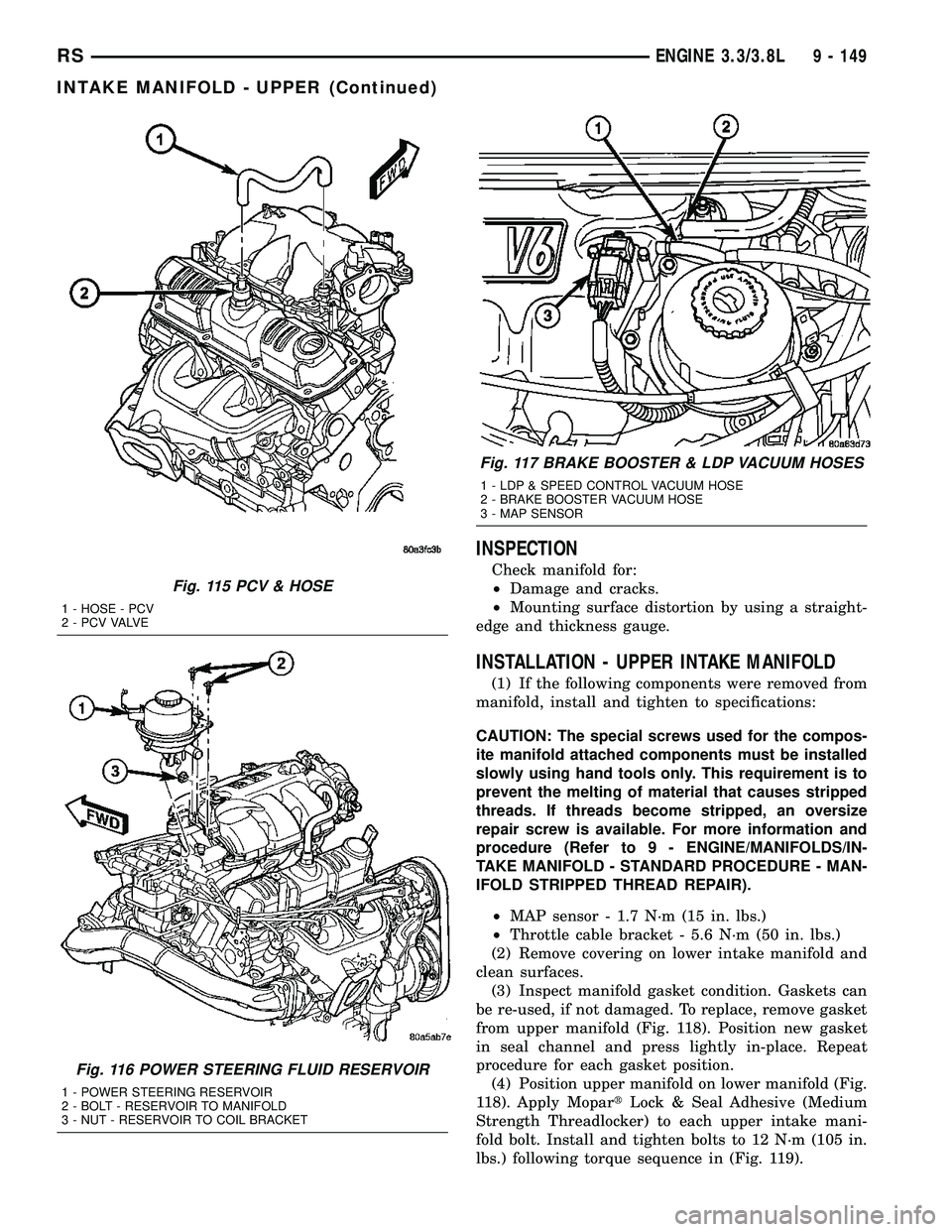
(9) Disconnect the PCV hose (Fig. 115).
(10) Remove the power steering reservoir attach-
ing bolts and only loosen the nut (Fig. 116). Lift res-
ervoir up to disengage lower mount from stud. Set
reservoir aside.Do notdisconnect hose.
(11) Disconnect the brake booster and leak detec-
tion pump (LDP) hoses from intake manifold (Fig.
117).
(12) Remove intake manifold bolts and remove the
manifold (Fig. 118).
(13) Cover the lower intake manifold with a suit-
able cover while the upper manifold is removed.
(14) Clean and inspect the upper intake manifold
(Refer to 9 - ENGINE/MANIFOLDS/INTAKE MANI-
FOLD - CLEANING) and (Refer to 9 - ENGINE/
MANIFOLDS/INTAKE MANIFOLD - INSPECTION).
CLEANING
(1) Discard gasket(s).
(2) Clean all sealing surfaces.
Fig. 114 Intake Manifold Port Repair
1 - BRAKE BOOSTER PORT = 1/49±18 NPT PIPE TAP
1 - LDP/SPEED CONTROL PORT = 1/89±18 NPT PIPE TAP
2 - DRILL BIT = 7/169BRAKE BOOSTER PORT
2 - DRILL BIT = 11/329LDP/SPEED CONTROL PORT
3 - INTAKE MANIFOLD
9 - 148 ENGINE 3.3/3.8LRS
INTAKE MANIFOLD - UPPER (Continued)
Page 1326 of 2339
INSPECTION
Check manifold for:
²Damage and cracks.
²Mounting surface distortion by using a straight-
edge and thickness gauge.
INSTALLATION - UPPER INTAKE MANIFOLD
(1) If the following components were removed from
manifold, install and tighten to specifications:
CAUTION: The special screws used for the compos-
ite manifold attached components must be installed
slowly using hand tools only. This requirement is to
prevent the melting of material that causes stripped
threads. If threads become stripped, an oversize
repair screw is available. For more information and
procedure (Refer to 9 - ENGINE/MANIFOLDS/IN-
TAKE MANIFOLD - STANDARD PROCEDURE - MAN-
IFOLD STRIPPED THREAD REPAIR).
²MAP sensor - 1.7 N´m (15 in. lbs.)
²Throttle cable bracket - 5.6 N´m (50 in. lbs.)
(2) Remove covering on lower intake manifold and
clean surfaces.
(3) Inspect manifold gasket condition. Gaskets can
be re-used, if not damaged. To replace, remove gasket
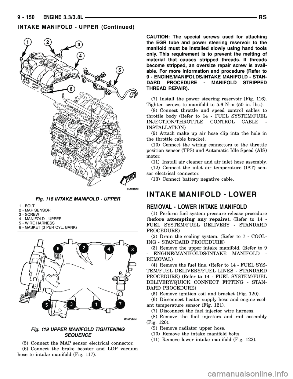
from upper manifold (Fig. 118). Position new gasket
in seal channel and press lightly in-place. Repeat
procedure for each gasket position.
(4) Position upper manifold on lower manifold (Fig.
118). Apply MopartLock & Seal Adhesive (Medium
Strength Threadlocker) to each upper intake mani-
fold bolt. Install and tighten bolts to 12 N´m (105 in.
lbs.) following torque sequence in (Fig. 119).
Fig. 115 PCV & HOSE
1 - HOSE - PCV
2 - P C V VA LV E
Fig. 116 POWER STEERING FLUID RESERVOIR
1 - POWER STEERING RESERVOIR
2 - BOLT - RESERVOIR TO MANIFOLD
3 - NUT - RESERVOIR TO COIL BRACKET
Fig. 117 BRAKE BOOSTER & LDP VACUUM HOSES
1 - LDP & SPEED CONTROL VACUUM HOSE
2 - BRAKE BOOSTER VACUUM HOSE
3 - MAP SENSOR
RSENGINE 3.3/3.8L9 - 149
INTAKE MANIFOLD - UPPER (Continued)
Page 1327 of 2339
(5) Connect the MAP sensor electrical connector.
(6) Connect the brake booster and LDP vacuum
hose to intake manifold (Fig. 117).CAUTION: The special screws used for attaching
the EGR tube and power steering reservoir to the
manifold must be installed slowly using hand tools
only. This requirement is to prevent the melting of
material that causes stripped threads. If threads
become stripped, an oversize repair screw is avail-
able. For more information and procedure (Refer to
9 - ENGINE/MANIFOLDS/INTAKE MANIFOLD - STAN-
DARD PROCEDURE - MANIFOLD STRIPPED
THREAD REPAIR).
(7) Install the power steering reservoir (Fig. 116).
Tighten screws to manifold to 5.6 N´m (50 in. lbs.).
(8) Connect throttle and speed control cables to
throttle body (Refer to 14 - FUEL SYSTEM/FUEL
INJECTION/THROTTLE CONTROL CABLE -
INSTALLATION)
(9) Attach make up air hose clip into the hole in
the throttle cable bracket.
(10) Connect the wiring connectors to the throttle
position sensor (TPS) and Automatic Idle Speed (AIS)
motor.
(11) Install air cleaner and air inlet hose assembly.
(12) Connect the inlet air temperature (IAT) sen-
sor electrical connector.
(13) Connect battery negative cable.
INTAKE MANIFOLD - LOWER
REMOVAL - LOWER INTAKE MANIFOLD
(1) Perform fuel system pressure release procedure
(before attempting any repairs).(Refer to 14 -
FUEL SYSTEM/FUEL DELIVERY - STANDARD
PROCEDURE)
(2) Drain the cooling system. (Refer to 7 - COOL-
ING - STANDARD PROCEDURE)
(3) Remove the upper intake manifold. (Refer to 9
- ENGINE/MANIFOLDS/INTAKE MANIFOLD -
REMOVAL)
(4) Remove the fuel line. (Refer to 14 - FUEL SYS-
TEM/FUEL DELIVERY/FUEL LINES - STANDARD
PROCEDURE) (Refer to 14 - FUEL SYSTEM/FUEL
DELIVERY/QUICK CONNECT FITTING - STAN-
DARD PROCEDURE)
(5) Remove ignition coil and bracket (Fig. 120).
(6) Disconnect heater supply hose and engine cool-
ant temperature sensor (Fig. 121).
(7) Disconnect the fuel injector wire harness.
(8) Remove the fuel injectors and rail assembly
(Fig. 120).
(9) Remove radiator upper hose.
(10) Remove the intake manifold bolts.
(11) Remove lower intake manifold (Fig. 122).
Fig. 118 INTAKE MANIFOLD - UPPER
1 - BOLT
2 - MAP SENSOR
3 - SCREW
4 - MANIFOLD - UPPER
5 - WIRE HARNESS
6 - GASKET (3 PER CYL. BANK)
Fig. 119 UPPER MANIFOLD TIGHTENING
SEQUENCE
9 - 150 ENGINE 3.3/3.8LRS
INTAKE MANIFOLD - UPPER (Continued)
Page 1340 of 2339
(5) Apply the park brake and start the engine.
(6) With transmission in Park or Neutral, raise
engine speed to 2000 RPM. Monitor the pressure
readings on the DRBIIIt. Back pressure should not
exceed specified limit. Refer to specification in table
below EXHAUST BACK PRESSURE LIMITS.
(7) If pressure exceeds maximum limits, inspect
exhaust system for restricted component. For further
catalytic converter inspection procedures, (Refer to 11
- EXHAUST SYSTEM/CATALYTIC CONVERTER -
INSPECTION). Replace component(s) as necessary.
EXHAUST BACK PRESSURE LIMITS
Exhaust Back Pressure Limit (Max)
Vehicle in Park/Neutral
(no load) @2000 RPM3.45 Kpa (0.5 psi)
INSPECTION
Inspect the exhaust pipes, catalytic converters,
muffler, and resonators for cracked joints, broken
welds and corrosion damage that would result in a
leaking exhaust system. Inspect the clamps, support
brackets, and insulators for cracks and corrosion
damage.
NOTE: Slip joint band clamps are spot welded to
exhaust system. If a band clamp must be replaced,
the spot weld must be ground off.
ADJUSTMENTS
A misaligned exhaust system is usually indicated
by a vibration, rattling noise, or binding of exhaust
system components. These noises are sometimes hard
to distinguish from other chassis noises. Inspect
exhaust system for broken, damaged or loose compo-
nents such as; clamps, heat shields, isolators, and
hanger brackets. Replace or tighten as necessary. It
is important that exhaust system clearances and
alignment be maintained.
Perform the following procedures to align the
exhaust system:
(1) Loosen band clamp at catalytic converter pipe
to muffler/resonator assembly.
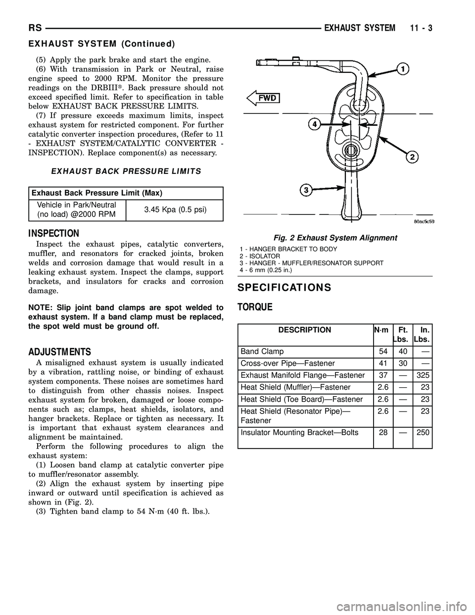
(2) Align the exhaust system by inserting pipe
inward or outward until specification is achieved as
shown in (Fig. 2).
(3) Tighten band clamp to 54 N´m (40 ft. lbs.).
SPECIFICATIONS
TORQUE
DESCRIPTION N´m Ft.
Lbs.In.
Lbs.
Band Clamp 54 40 Ð
Cross-over PipeÐFastener 41 30 Ð
Exhaust Manifold FlangeÐFastener 37 Ð 325
Heat Shield (Muffler)ÐFastener 2.6 Ð 23
Heat Shield (Toe Board)ÐFastener 2.6 Ð 23
Heat Shield (Resonator Pipe)Ð
Fastener2.6 Ð 23
Insulator Mounting BracketÐBolts 28 Ð 250
Fig. 2 Exhaust System Alignment
1 - HANGER BRACKET TO BODY
2 - ISOLATOR
3 - HANGER - MUFFLER/RESONATOR SUPPORT
4-6mm(0.25 in.)
RSEXHAUST SYSTEM11-3
EXHAUST SYSTEM (Continued)
Page 1361 of 2339
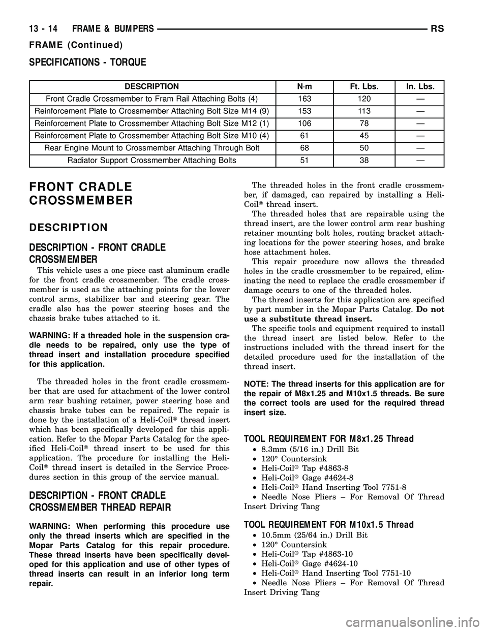
SPECIFICATIONS - TORQUE
DESCRIPTION N´m Ft. Lbs. In. Lbs.
Front Cradle Crossmember to Fram Rail Attaching Bolts (4) 163 120 Ð
Reinforcement Plate to Crossmember Attaching Bolt Size M14 (9) 153 113 Ð
Reinforcement Plate to Crossmember Attaching Bolt Size M12 (1) 106 78 Ð
Reinforcement Plate to Crossmember Attaching Bolt Size M10 (4) 61 45 Ð
Rear Engine Mount to Crossmember Attaching Through Bolt 68 50 Ð
Radiator Support Crossmember Attaching Bolts 51 38 Ð
FRONT CRADLE
CROSSMEMBER
DESCRIPTION
DESCRIPTION - FRONT CRADLE
CROSSMEMBER
This vehicle uses a one piece cast aluminum cradle
for the front cradle crossmember. The cradle cross-
member is used as the attaching points for the lower
control arms, stabilizer bar and steering gear. The
cradle also has the power steering hoses and the
chassis brake tubes attached to it.
WARNING: If a threaded hole in the suspension cra-
dle needs to be repaired, only use the type of
thread insert and installation procedure specified
for this application.
The threaded holes in the front cradle crossmem-
ber that are used for attachment of the lower control
arm rear bushing retainer, power steering hose and
chassis brake tubes can be repaired. The repair is
done by the installation of a Heli-Coiltthread insert
which has been specifically developed for this appli-
cation. Refer to the Mopar Parts Catalog for the spec-
ified Heli-Coiltthread insert to be used for this
application. The procedure for installing the Heli-
Coiltthread insert is detailed in the Service Proce-
dures section in this group of the service manual.
DESCRIPTION - FRONT CRADLE
CROSSMEMBER THREAD REPAIR
WARNING: When performing this procedure use
only the thread inserts which are specified in the
Mopar Parts Catalog for this repair procedure.
These thread inserts have been specifically devel-
oped for this application and use of other types of
thread inserts can result in an inferior long term
repair.The threaded holes in the front cradle crossmem-
ber, if damaged, can repaired by installing a Heli-
Coiltthread insert.
The threaded holes that are repairable using the
thread insert, are the lower control arm rear bushing
retainer mounting bolt holes, routing bracket attach-
ing locations for the power steering hoses, and brake
hose attachment holes.
This repair procedure now allows the threaded
holes in the cradle crossmember to be repaired, elim-
inating the need to replace the cradle crossmember if
damage occurs to one of the threaded holes.
The thread inserts for this application are specified
by part number in the Mopar Parts Catalog.Do not
use a substitute thread insert.
The specific tools and equipment required to install
the thread insert are listed below. Refer to the
instructions included with the thread insert for the
detailed procedure used for the installation of the
thread insert.
NOTE: The thread inserts for this application are for
the repair of M8x1.25 and M10x1.5 threads. Be sure
the correct tools are used for the required thread
insert size.
TOOL REQUIREMENT FOR M8x1.25 Thread
²8.3mm (5/16 in.) Drill Bit
²120É Countersink
²Heli-CoiltTap #4863-8
²Heli-CoiltGage #4624-8
²Heli-CoiltHand Inserting Tool 7751-8
²Needle Nose Pliers ± For Removal Of Thread
Insert Driving Tang
TOOL REQUIREMENT FOR M10x1.5 Thread
²10.5mm (25/64 in.) Drill Bit
²120É Countersink
²Heli-CoiltTap #4863-10
²Heli-CoiltGage #4624-10
²Heli-CoiltHand Inserting Tool 7751-10
²Needle Nose Pliers ± For Removal Of Thread
Insert Driving Tang
13 - 14 FRAME & BUMPERSRS
FRAME (Continued)