2005 CHRYSLER VOYAGER compression ratio
[x] Cancel search: compression ratioPage 1253 of 2339
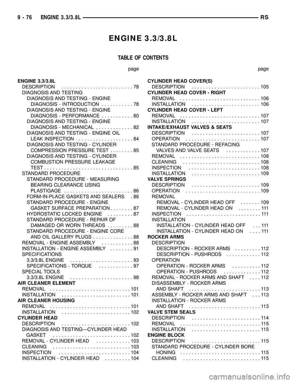
ENGINE 3.3/3.8L
TABLE OF CONTENTS
page page
ENGINE 3.3/3.8L
DESCRIPTION.........................78
DIAGNOSIS AND TESTING
DIAGNOSIS AND TESTING - ENGINE
DIAGNOSIS - INTRODUCTION...........78
DIAGNOSIS AND TESTING - ENGINE
DIAGNOSIS - PERFORMANCE...........80
DIAGNOSIS AND TESTING - ENGINE
DIAGNOSIS - MECHANICAL.............82
DIAGNOSIS AND TESTING - ENGINE OIL
LEAK INSPECTION....................84
DIAGNOSIS AND TESTING - CYLINDER
COMPRESSION PRESSURE TEST........85
DIAGNOSIS AND TESTING - CYLINDER
COMBUSTION PRESSURE LEAKAGE
TEST...............................85
STANDARD PROCEDURE
STANDARD PROCEDURE - MEASURING
BEARING CLEARANCE USING
PLASTIGAGE........................86
FORM-IN-PLACE GASKETS AND SEALERS . 86
STANDARD PROCEDURE - ENGINE
GASKET SURFACE PREPARATION........87
HYDROSTATIC LOCKED ENGINE.........87
STANDARD PROCEDURE - REPAIR OF
DAMAGED OR WORN THREADS.........88
STANDARD PROCEDURE - ENGINE CORE
AND OIL GALLERY PLUGS..............88
REMOVAL - ENGINE ASSEMBLY...........88
INSTALLATION - ENGINE ASSEMBLY........91
SPECIFICATIONS
3.3/3.8L ENGINE......................93
SPECIFICATIONS - TORQUE............97
SPECIAL TOOLS
3.3/3.8L ENGINE......................98
AIR CLEANER ELEMENT
REMOVAL............................101
INSTALLATION........................101
AIR CLEANER HOUSING
REMOVAL............................101
INSTALLATION........................102
CYLINDER HEAD
DESCRIPTION........................102
DIAGNOSIS AND TESTINGÐCYLINDER HEAD
GASKET...........................102
REMOVAL - CYLINDER HEAD............103
CLEANING...........................103
INSPECTION.........................104
INSTALLATION - CYLINDER HEAD.........104CYLINDER HEAD COVER(S)
DESCRIPTION........................105
CYLINDER HEAD COVER - RIGHT
REMOVAL............................106
INSTALLATION........................106
CYLINDER HEAD COVER - LEFT
REMOVAL............................107
INSTALLATION........................107
INTAKE/EXHAUST VALVES & SEATS
DESCRIPTION........................107
OPERATION..........................107
STANDARD PROCEDURE - REFACING
VALVESANDVALVESEATS ............107
REMOVAL............................108
CLEANING...........................108
INSPECTION.........................108
INSTALLATION........................109
VALVE SPRINGS
DESCRIPTION........................109
OPERATION..........................109
REMOVAL
REMOVAL - CYLINDER HEAD OFF.......109
REMOVAL - CYLINDER HEAD ON........111
INSPECTION..........................111
INSTALLATION
INSTALLATION - CYLINDER HEAD OFF . . . 111
INSTALLATION - CYLINDER HEAD ON....111
ROCKER ARMS
DESCRIPTION
DESCRIPTION - ROCKER ARMS.........112
DESCRIPTION - PUSHRODS............112
OPERATION
OPERATION - ROCKER ARMS..........112
OPERATION - PUSHRODS.............112
REMOVAL - ROCKER ARMS AND SHAFT....112
DISASSEMBLY - ROCKER ARMS
AND SHAFT.........................113
ASSEMBLY - ROCKER ARMS AND SHAFT . . . 113
INSTALLATION - ROCKER ARMS
AND SHAFT.........................113
VALVE STEM SEALS
DESCRIPTION........................114
REMOVAL............................115
INSTALLATION........................115
ENGINE BLOCK
DESCRIPTION........................115
STANDARD PROCEDURE - CYLINDER BORE
HONING............................115
CLEANING...........................115
9 - 76 ENGINE 3.3/3.8LRS
Page 1258 of 2339
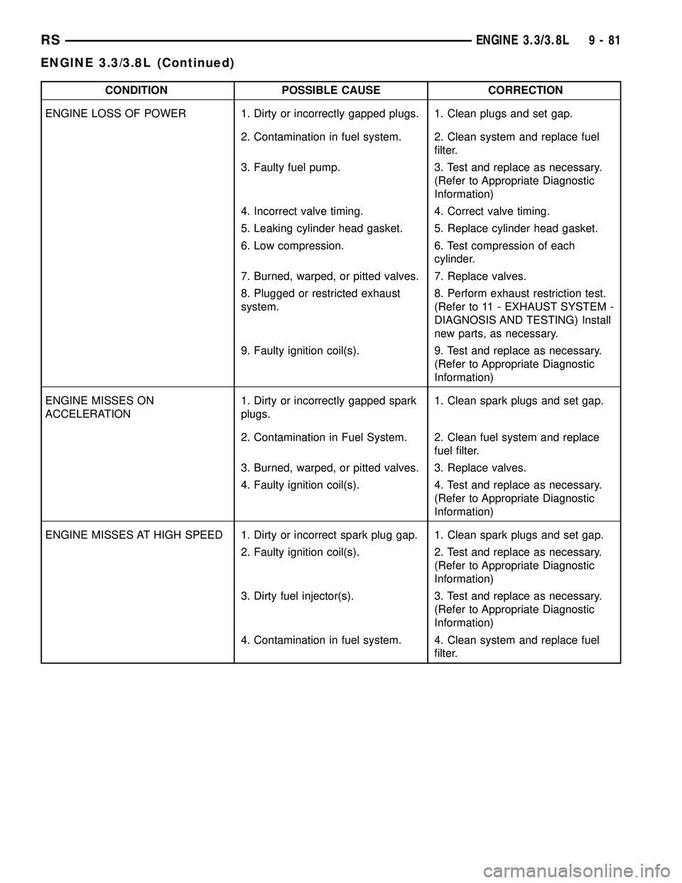
CONDITION POSSIBLE CAUSE CORRECTION
ENGINE LOSS OF POWER 1. Dirty or incorrectly gapped plugs. 1. Clean plugs and set gap.
2. Contamination in fuel system. 2. Clean system and replace fuel
filter.
3. Faulty fuel pump. 3. Test and replace as necessary.
(Refer to Appropriate Diagnostic
Information)
4. Incorrect valve timing. 4. Correct valve timing.
5. Leaking cylinder head gasket. 5. Replace cylinder head gasket.
6. Low compression. 6. Test compression of each
cylinder.
7. Burned, warped, or pitted valves. 7. Replace valves.
8. Plugged or restricted exhaust
system.8. Perform exhaust restriction test.
(Refer to 11 - EXHAUST SYSTEM -
DIAGNOSIS AND TESTING) Install
new parts, as necessary.
9. Faulty ignition coil(s). 9. Test and replace as necessary.
(Refer to Appropriate Diagnostic
Information)
ENGINE MISSES ON
ACCELERATION1. Dirty or incorrectly gapped spark
plugs.1. Clean spark plugs and set gap.
2. Contamination in Fuel System. 2. Clean fuel system and replace
fuel filter.
3. Burned, warped, or pitted valves. 3. Replace valves.
4. Faulty ignition coil(s). 4. Test and replace as necessary.
(Refer to Appropriate Diagnostic
Information)
ENGINE MISSES AT HIGH SPEED 1. Dirty or incorrect spark plug gap. 1. Clean spark plugs and set gap.
2. Faulty ignition coil(s). 2. Test and replace as necessary.
(Refer to Appropriate Diagnostic
Information)
3. Dirty fuel injector(s). 3. Test and replace as necessary.
(Refer to Appropriate Diagnostic
Information)
4. Contamination in fuel system. 4. Clean system and replace fuel
filter.
RSENGINE 3.3/3.8L9-81
ENGINE 3.3/3.8L (Continued)
Page 1270 of 2339
(49) Install the radiator upper support crossmem-
ber (Refer to 23 - BODY/EXTERIOR/GRILLE OPEN-
ING REINFORCEMENT - INSTALLATION).
(50) Install the wiper module (Refer to 8 - ELEC-
TRICAL/WIPERS/WASHERS/WIPER MODULE -
INSTALLATION).
(51) Connect the fuel line to fuel rail (Refer to 14 -
FUEL SYSTEM/FUEL DELIVERY/FUEL LINES -
STANDARD PROCEDURE).
(52) Install the air cleaner and hoses.
(53) Install new oil filter. Fill engine crankcase
with proper oil to correct level.
(54) Connect negative cable to battery.
(55) Fill the cooling system (Refer to 7 - COOLING
- STANDARD PROCEDURE).
(56) Start engine and run until operating temper-
ature is reached.
(57) Adjust transmission linkage, if necessary.
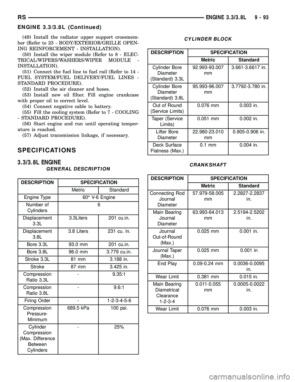
SPECIFICATIONS
3.3/3.8L ENGINE
GENERAL DESCRIPTION
DESCRIPTION SPECIFICATION
Metric Standard
Engine Type 60É V-6 Engine
Number of
Cylinders6
Displacement
3.3L3.3Liters 201 cu.in.
Displacement
3.8L3.8 Liters 231 cu. in.
Bore 3.3L 93.0 mm 201 cu.in.
Bore 3.8L 96.0 mm 3.779 cu.in.
Stroke 3.3L 81 mm 3.188 in.
Stroke 87 mm 3.425 in.
Compression
Ratio 3.3L- 9.35:1
Compression
Ratio 3.8L- 9.6:1
Firing Order - 1-2-3-4-5-6
Compression
Pressure-
Minimum689.5 kPa 100 psi.
Cylinder
Compression
(Max. Difference
Between
Cylinders- 25%
CYLINDER BLOCK
DESCRIPTION SPECIFICATION
Metric Standard
Cylinder Bore
Diameter
(Standard) 3.3L92.993-93.007
mm3.661-3.6617 in.
Cylinder Bore
Diameter
(Standard) 3.8L95.993-96.007
mm3.7792-3.780 in.
Out of Round
(Service Limits)0.076 mm 0.003 in.
Taper (Service
Limits)0.051 mm 0.002 in.
Lifter Bore
Diameter22.980-23.010
mm0.905-0.906 in.
Deck Surface
Flatness (Max.)0.1 mm 0.004 in.
CRANKSHAFT
DESCRIPTION SPECIFICATION
Metric Standard
Connecting Rod
Journal
Diameter57.979-58.005
mm2.2827-2.2837
in.
Main Bearing
Journal
Diameter63.993-64.013
mm2.5194-2.5202
in.
Journal
Out-of-Round
(Max.)0.025 mm 0.001 in.
Journal Taper
(Max.)0.025 mm 0.001 in
End Play 0.09-0.24 mm 0.0036-0.0095
in.
Wear Limit 0.381 mm 0.015 in.
Main Bearing
Diametrical
Clearance
1-2-3-40.011-0.055
mm0.0005-0.0022
in.
Wear Limit 0.076 mm 0.003 in.
RSENGINE 3.3/3.8L9-93
ENGINE 3.3/3.8L (Continued)
Page 1272 of 2339
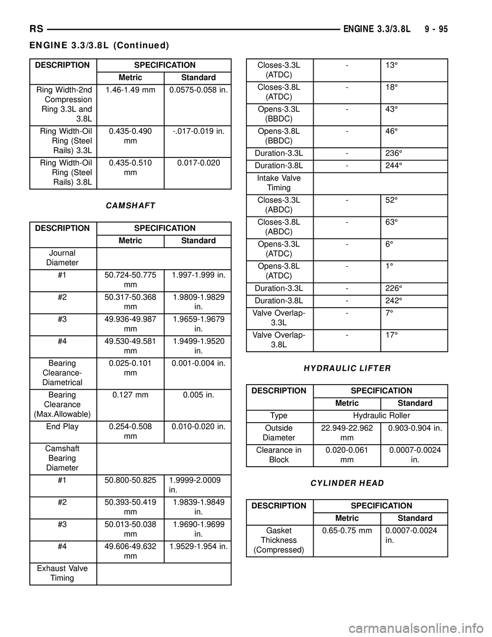
DESCRIPTION SPECIFICATION
Metric Standard
Ring Width-2nd
Compression
Ring 3.3L and
3.8L1.46-1.49 mm 0.0575-0.058 in.
Ring Width-Oil
Ring (Steel
Rails) 3.3L0.435-0.490
mm-.017-0.019 in.
Ring Width-Oil
Ring (Steel
Rails) 3.8L0.435-0.510
mm0.017-0.020
CAMSHAFT
DESCRIPTION SPECIFICATION
Metric Standard
Journal
Diameter
#1 50.724-50.775
mm1.997-1.999 in.
#2 50.317-50.368
mm1.9809-1.9829
in.
#3 49.936-49.987
mm1.9659-1.9679
in.
#4 49.530-49.581
mm1.9499-1.9520
in.
Bearing
Clearance-
Diametrical0.025-0.101
mm0.001-0.004 in.
Bearing
Clearance
(Max.Allowable)0.127 mm 0.005 in.
End Play 0.254-0.508
mm0.010-0.020 in.
Camshaft
Bearing
Diameter
#1 50.800-50.825 1.9999-2.0009
in.
#2 50.393-50.419
mm1.9839-1.9849
in.
#3 50.013-50.038
mm1.9690-1.9699
in.
#4 49.606-49.632
mm1.9529-1.954 in.
Exhaust Valve
Timing
Closes-3.3L
(ATDC)- 13É
Closes-3.8L
(ATDC)- 18É
Opens-3.3L
(BBDC)- 43É
Opens-3.8L
(BBDC)- 46É
Duration-3.3L - 236É
Duration-3.8L - 244É
Intake Valve
Timing
Closes-3.3L
(ABDC)- 52É
Closes-3.8L
(ABDC)- 63É
Opens-3.3L
(ATDC)-6É
Opens-3.8L
(ATDC)-1É
Duration-3.3L - 226É
Duration-3.8L - 242É
Valve Overlap-
3.3L-7É
Valve Overlap-
3.8L- 17É
HYDRAULIC LIFTER
DESCRIPTION SPECIFICATION
Metric Standard
Type Hydraulic Roller
Outside
Diameter22.949-22.962
mm0.903-0.904 in.
Clearance in
Block0.020-0.061
mm0.0007-0.0024
in.
CYLINDER HEAD
DESCRIPTION SPECIFICATION
Metric Standard
Gasket
Thickness
(Compressed)0.65-0.75 mm 0.0007-0.0024
in.
RSENGINE 3.3/3.8L9-95
ENGINE 3.3/3.8L (Continued)
Page 1279 of 2339
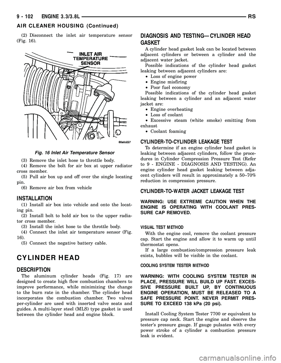
(2) Disconnect the inlet air temperature sensor
(Fig. 16).
(3) Remove the inlet hose to throttle body.
(4) Remove the bolt for air box at upper radiator
cross member.
(5) Pull air box up and off over the single locating
pin.
(6) Remove air box from vehicle
INSTALLATION
(1) Install air box into vehicle and onto the locat-
ing pin.
(2) Install bolt to hold air box to the upper radia-
tor cross member.
(3) Install the inlet hose to the throttle body.
(4) Connect the inlet air temperature sensor (Fig.
16).
(5) Connect the negative battery cable.
CYLINDER HEAD
DESCRIPTION
The aluminum cylinder heads (Fig. 17) are
designed to create high flow combustion chambers to
improve performance, while minimizing the change
to the burn rate in the chamber. The cylinder head
incorporates the combustion chamber. Two valves
per-cylinder are used with inserted valve seats and
guides. A multi-layer steel (MLS) type gasket is used
between the cylinder head and engine block.
DIAGNOSIS AND TESTINGÐCYLINDER HEAD
GASKET
A cylinder head gasket leak can be located between
adjacent cylinders or between a cylinder and the
adjacent water jacket.
Possible indications of the cylinder head gasket
leaking between adjacent cylinders are:
²Loss of engine power
²Engine misfiring
²Poor fuel economy
Possible indications of the cylinder head gasket
leaking between a cylinder and an adjacent water
jacket are:
²Engine overheating
²Loss of coolant
²Excessive steam (white smoke) emitting from
exhaust
²Coolant foaming
CYLINDER-TO-CYLINDER LEAKAGE TEST
To determine if an engine cylinder head gasket is
leaking between adjacent cylinders, follow the proce-
dures in Cylinder Compression Pressure Test (Refer
to 9 - ENGINE - DIAGNOSIS AND TESTING). An
engine cylinder head gasket leaking between adja-
cent cylinders will result in approximately a 50±70%
reduction in compression pressure.
CYLINDER-TO-WATER JACKET LEAKAGE TEST
WARNING: USE EXTREME CAUTION WHEN THE
ENGINE IS OPERATING WITH COOLANT PRES-
SURE CAP REMOVED.
VISUAL TEST METHOD
With the engine cool, remove the coolant pressure
cap. Start the engine and allow it to warm up until
thermostat opens.
If a large combustion/compression pressure leak
exists, bubbles will be visible in the coolant.
COOLING SYSTEM TESTER METHOD
WARNING: WITH COOLING SYSTEM TESTER IN
PLACE, PRESSURE WILL BUILD UP FAST. EXCES-
SIVE PRESSURE BUILT UP, BY CONTINUOUS
ENGINE OPERATION, MUST BE RELEASED TO A
SAFE PRESSURE POINT. NEVER PERMIT PRES-
SURE TO EXCEED 138 kPa (20 psi).
Install Cooling System Tester 7700 or equivalent to
pressure cap neck. Start the engine and observe the
tester's pressure gauge. If gauge pulsates with every
power stroke of a cylinder a combustion pressure
leak is evident.
Fig. 16 Inlet Air Temperature Sensor
9 - 102 ENGINE 3.3/3.8LRS
AIR CLEANER HOUSING (Continued)
Page 1298 of 2339
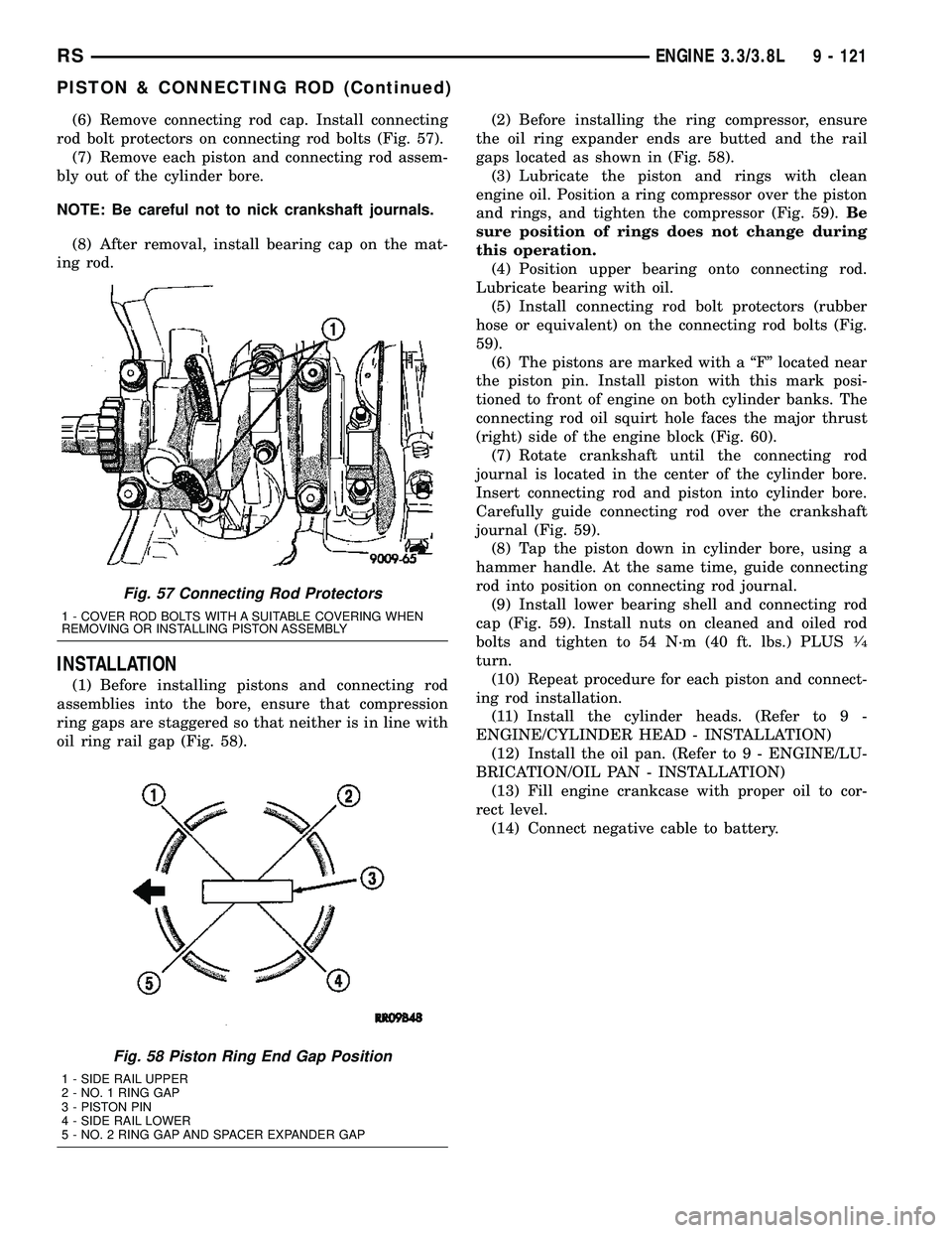
(6) Remove connecting rod cap. Install connecting
rod bolt protectors on connecting rod bolts (Fig. 57).
(7) Remove each piston and connecting rod assem-
bly out of the cylinder bore.
NOTE: Be careful not to nick crankshaft journals.
(8) After removal, install bearing cap on the mat-
ing rod.
INSTALLATION
(1) Before installing pistons and connecting rod
assemblies into the bore, ensure that compression
ring gaps are staggered so that neither is in line with
oil ring rail gap (Fig. 58).(2) Before installing the ring compressor, ensure
the oil ring expander ends are butted and the rail
gaps located as shown in (Fig. 58).
(3) Lubricate the piston and rings with clean
engine oil. Position a ring compressor over the piston
and rings, and tighten the compressor (Fig. 59).Be
sure position of rings does not change during
this operation.
(4) Position upper bearing onto connecting rod.
Lubricate bearing with oil.
(5) Install connecting rod bolt protectors (rubber
hose or equivalent) on the connecting rod bolts (Fig.
59).
(6) The pistons are marked with a ªFº located near
the piston pin. Install piston with this mark posi-
tioned to front of engine on both cylinder banks. The
connecting rod oil squirt hole faces the major thrust
(right) side of the engine block (Fig. 60).
(7) Rotate crankshaft until the connecting rod
journal is located in the center of the cylinder bore.
Insert connecting rod and piston into cylinder bore.
Carefully guide connecting rod over the crankshaft
journal (Fig. 59).
(8) Tap the piston down in cylinder bore, using a
hammer handle. At the same time, guide connecting
rod into position on connecting rod journal.
(9) Install lower bearing shell and connecting rod
cap (Fig. 59). Install nuts on cleaned and oiled rod
bolts and tighten to 54 N´m (40 ft. lbs.) PLUS
1¤4
turn.
(10) Repeat procedure for each piston and connect-
ing rod installation.
(11) Install the cylinder heads. (Refer to 9 -
ENGINE/CYLINDER HEAD - INSTALLATION)
(12) Install the oil pan. (Refer to 9 - ENGINE/LU-
BRICATION/OIL PAN - INSTALLATION)
(13) Fill engine crankcase with proper oil to cor-
rect level.
(14) Connect negative cable to battery.
Fig. 57 Connecting Rod Protectors
1 - COVER ROD BOLTS WITH A SUITABLE COVERING WHEN
REMOVING OR INSTALLING PISTON ASSEMBLY
Fig. 58 Piston Ring End Gap Position
1 - SIDE RAIL UPPER
2 - NO. 1 RING GAP
3 - PISTON PIN
4 - SIDE RAIL LOWER
5 - NO. 2 RING GAP AND SPACER EXPANDER GAP
RSENGINE 3.3/3.8L9 - 121
PISTON & CONNECTING ROD (Continued)
Page 1812 of 2339
(e) Pivot lower roller arm outward to increase
seal compression.
(f) Tighten lower roller arm bolts to 13 N´m (115
in. lbs.) torque.
(g) Verify alignment, adjust as necessary.
NOTE: Adjusting seal compression at the B-pillar
can affect door flushness the C-pillar.
STABILIZER ADJUSTMENT - UPPER/LOWER
(1) Open sliding door.
(2) Loosen the bolts holding the male stabilizers to
the sliding door enough that the stabilizers can move
with some effort.
(3) Close and then reopen sliding door.
(4) Tighten all stabilizers bolts.
STABILIZER
REMOVAL
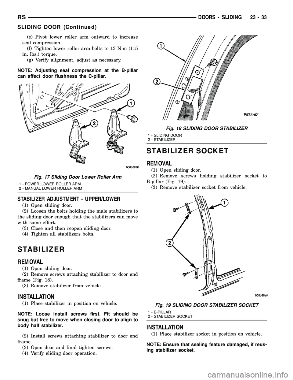
(1) Open sliding door.
(2) Remove screws attaching stabilizer to door end
frame (Fig. 18).
(3) Remove stabilizer from vehicle.
INSTALLATION
(1) Place stabilizer in position on vehicle.
NOTE: Loose install screws first. Fit should be
snug but free to move when closing door to align to
body half stabilizer.
(2) Install screws attaching stabilizer to door end
frame.
(3) Open door and final tighten screws.
(4) Verify sliding door operation.
STABILIZER SOCKET
REMOVAL
(1) Open sliding door.
(2) Remove screws holding stabilizer socket to
B-pillar (Fig. 19).
(3) Remove stabilizer socket from vehicle.
INSTALLATION
(1) Place stabilizer socket in position on vehicle.
NOTE: Ensure that sealing feature damaged, if reus-
ing stabilizer socket.
Fig. 17 Sliding Door Lower Roller Arm
1 - POWER LOWER ROLLER ARM
2 - MANUAL LOWER ROLLER ARM
Fig. 18 SLIDING DOOR STABILIZER
1 - SLIDING DOOR
2 - STABILIZER
Fig. 19 SLIDING DOOR STABILIZER SOCKET
1 - B-PILLAR
2 - STABILIZER SOCKET
RSDOORS - SLIDING23-33
SLIDING DOOR (Continued)
Page 2279 of 2339
The major non-monitored circuits are listed below
along with examples of failures modes that do not
directly cause the PCM to set a DTC, but for a sys-
tem that is monitored.
FUEL PRESSURE
The fuel pressure regulator controls fuel system
pressure. The PCM cannot detect a clogged fuel
pump inlet filter, clogged in-line fuel filter, or a
pinched fuel supply or return line. However, these
could result in a rich or lean condition causing the
PCM to store an oxygen sensor, fuel system, or mis-
fire diagnostic trouble code.
SECONDARY IGNITION CIRCUIT
The PCM cannot detect an inoperative ignition coil,
fouled or worn spark plugs, ignition cross firing, or
open spark plug cables. The misfire will however,
increase the oxygen content in the exhaust, deceiving
the PCM in to thinking the fuel system is too lean.
Also see misfire detection. There are DTC's that can
detect misfire and Ionization shorts in the secondary
ignition circuit, refer to the Powertrain Diagnostic
manual for more information
CYLINDER COMPRESSION
The PCM cannot detect uneven, low, or high engine
cylinder compression. Low compression lowers O2
content in the exhaust. Leading to fuel system, oxy-
gen sensor, or misfire detection fault.
EXHAUST SYSTEM
The PCM cannot detect a plugged, restricted or
leaking exhaust system. It may set a EGR (if
equipped) or Fuel system or O2S fault.
FUEL INJECTOR MECHANICAL MALFUNCTIONS
The PCM cannot determine if a fuel injector is
clogged, the needle is sticking or if the wrong injector
is installed. However, these could result in a rich or
lean condition causing the PCM to store a diagnostic
trouble code for either misfire, an oxygen sensor, or
the fuel system.
EXCESSIVE OIL CONSUMPTION
Although the PCM monitors engine exhaust oxygen
content when the system is in closed loop, it cannot
determine excessive oil consumption.
THROTTLE BODY AIR FLOW
The PCM cannot detect a clogged or restricted air
cleaner inlet or filter element.
VACUUM ASSIST
The PCM cannot detect leaks or restrictions in the
vacuum circuits of vacuum assisted engine control
system devices. However, these could cause the PCMto store a MAP sensor diagnostic trouble code and
cause a high idle condition.
PCM SYSTEM GROUND
The PCM cannot determine a poor system ground.
However, one or more diagnostic trouble codes may
be generated as a result of this condition. The mod-
ule should be mounted to the body at all times,
including when diagnostics are performed.
PCM CONNECTOR ENGAGEMENT
The PCM may not be able to determine spread or
damaged connector pins. However, it might store
diagnostic trouble codes as a result of spread connec-
tor pins.
DESCRIPTION - MONITORED SYSTEMS
There are new electronic circuit monitors that
check fuel, emission, engine and ignition perfor-
mance. These monitors use information from various
sensor circuits to indicate the overall operation of the
fuel, engine, ignition and emission systems and thus
the emissions performance of the vehicle.
The fuel, engine, ignition and emission systems
monitors do not indicate a specific component prob-
lem. They do indicate that there is an implied prob-
lem within one of the systems and that a specific
problem must be diagnosed.
If any of these monitors detect a problem affecting
vehicle emissions, the Malfunction Indicator (Check
Engine) Lamp will be illuminated. These monitors
generate Diagnostic Trouble Codes that can be dis-
played with the a scan tool.
The following is a list of the system monitors:
²EGR Monitor (if equipped)
²Misfire Monitor
²Fuel System Monitor
²Oxygen Sensor Monitor
²Oxygen Sensor Heater Monitor
²Catalyst Monitor
²Evaporative System Leak Detection Monitor (if
equipped)
Following is a description of each system monitor,
and its DTC.
Refer to the appropriate Powertrain Diagnos-
tics Procedures manual for diagnostic proce-
dures.
OXYGEN SENSOR (O2S) MONITOR
Effective control of exhaust emissions is achieved
by an oxygen feedback system. The most important
element of the feedback system is the O2S. The O2S
is located in the exhaust path. Once it reaches oper-
ating temperatures of 300É to 350ÉC (572É to 662ÉF),
the sensor generates a voltage that is inversely pro-
portional to the amount of oxygen in the exhaust.
25 - 6 EMISSIONS CONTROLRS
EMISSIONS CONTROL (Continued)