2005 CHRYSLER VOYAGER oil temperature
[x] Cancel search: oil temperaturePage 2164 of 2339
CONTROLS - FRONT
TABLE OF CONTENTS
page page
A/C COMPRESSOR CLUTCH/COIL
DESCRIPTION.........................13
OPERATION...........................13
DIAGNOSIS AND TESTING
A/C COMPRESSOR CLUTCH COIL........14
STANDARD PROCEDURE
CLUTCH INSPECTION.................15
A/C CLUTCH BREAK-IN................15
REMOVAL.............................15
INSTALLATION.........................16
A/C COMPRESSOR CLUTCH RELAY
DESCRIPTION.........................18
OPERATION...........................18
REMOVAL.............................19
INSTALLATION.........................19
A/C HEATER CONTROL
DESCRIPTION.........................19
STANDARD PROCEDURE
A/C-HEATER CONTROL CALIBRATION.....19
REMOVAL.............................20
INSTALLATION.........................20
A/C PRESSURE TRANSDUCER
DESCRIPTION.........................20
OPERATION...........................20
DIAGNOSIS AND TESTING
A/C PRESSURE TRANSDUCER..........21
REMOVAL.............................21
INSTALLATION.........................21
BLEND DOOR ACTUATOR
DESCRIPTION.........................22
OPERATION...........................22
REMOVAL.............................22
INSTALLATION.........................22
BLOWER MOTOR RELAY
DESCRIPTION.........................23
OPERATION...........................23
REMOVAL.............................24INSTALLATION.........................24
BLOWER MOTOR RESISTOR BLOCK
DESCRIPTION.........................24
OPERATION...........................24
DIAGNOSIS AND TESTING
FRONT BLOWER MOTOR RESISTOR
BLOCK.............................25
REMOVAL.............................25
INSTALLATION.........................25
EVAPORATOR TEMPERATURE SENSOR
DESCRIPTION.........................26
OPERATION...........................27
REMOVAL
RG MODELS.........................27
RS MODELS.........................27
INSTALLATION
RG MODELS.........................27
RS MODELS.........................28
INFRARED TEMPERATURE SENSOR
DESCRIPTION.........................28
OPERATION...........................28
MODE DOOR ACTUATOR
DESCRIPTION.........................29
OPERATION...........................29
REMOVAL.............................29
INSTALLATION.........................30
POWER MODULE - BLOWER MOTOR
DESCRIPTION.........................30
OPERATION...........................30
REMOVAL.............................30
INSTALLATION.........................31
RECIRCULATION DOOR ACTUATOR
DESCRIPTION.........................31
OPERATION...........................31
REMOVAL.............................32
INSTALLATION.........................32
A/C COMPRESSOR CLUTCH/
COIL
DESCRIPTION
The A/C compressor clutch assembly consists of a
stationary electromagnetic A/C clutch field coil with a
zener diode, a pulley bearing and pulley assembly,
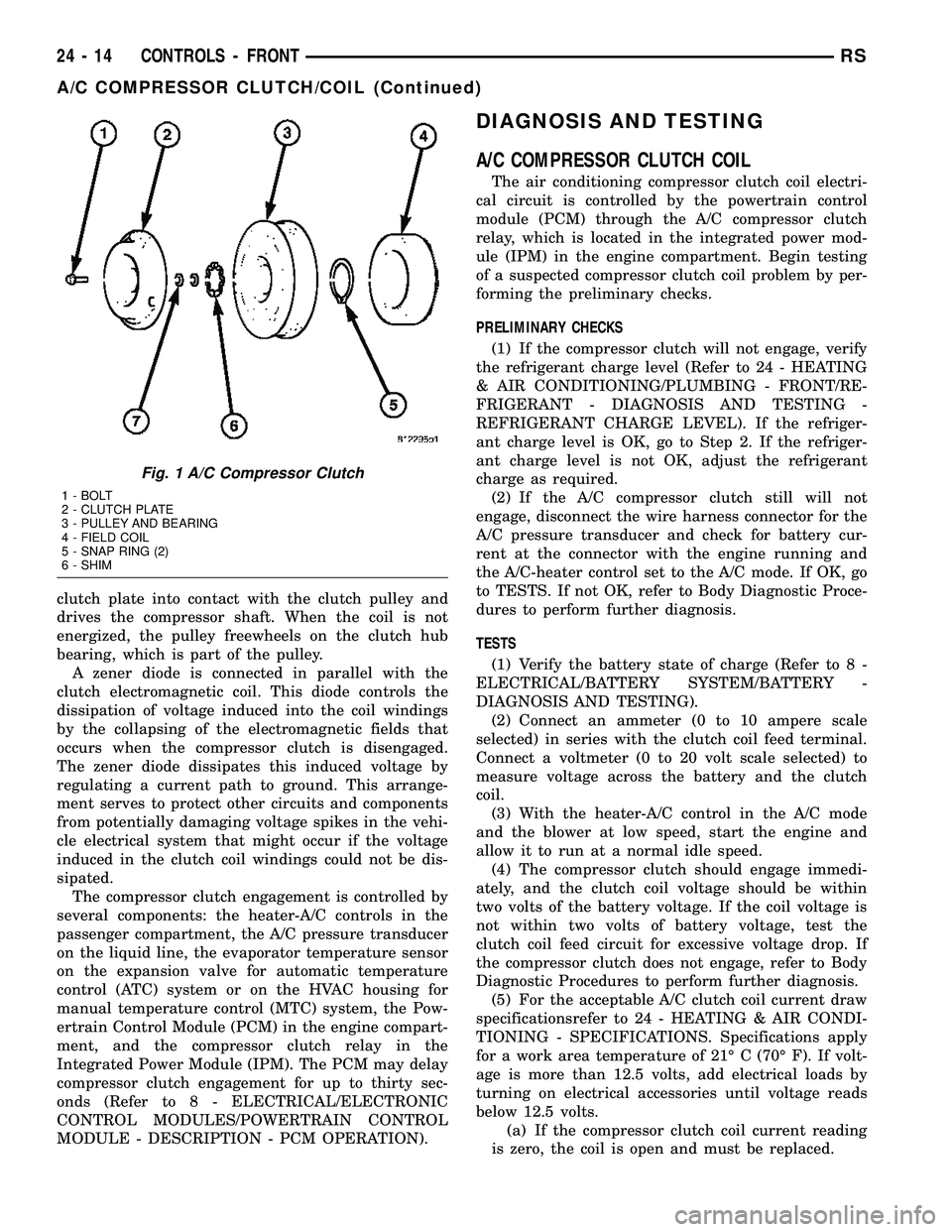
and a clutch plate (Fig. 1). These components provide
the means to engage and disengage the A/C compres-
sor from the engine accessory drive belt.The A/C clutch field coil and the pulley bearing
and pulley assembly are both retained on the nose of
the A/C compressor with snap rings. The clutch plate
is splined to the compressor shaft and secured with a
bolt.
OPERATION
The compressor clutch components provide the
means to engage and disengage the compressor from
the engine serpentine accessory drive belt. When the
clutch coil is energized, it magnetically draws the
RSCONTROLS - FRONT24-13
Page 2165 of 2339
clutch plate into contact with the clutch pulley and
drives the compressor shaft. When the coil is not
energized, the pulley freewheels on the clutch hub
bearing, which is part of the pulley.
A zener diode is connected in parallel with the
clutch electromagnetic coil. This diode controls the
dissipation of voltage induced into the coil windings
by the collapsing of the electromagnetic fields that
occurs when the compressor clutch is disengaged.
The zener diode dissipates this induced voltage by
regulating a current path to ground. This arrange-
ment serves to protect other circuits and components
from potentially damaging voltage spikes in the vehi-
cle electrical system that might occur if the voltage
induced in the clutch coil windings could not be dis-
sipated.
The compressor clutch engagement is controlled by
several components: the heater-A/C controls in the
passenger compartment, the A/C pressure transducer
on the liquid line, the evaporator temperature sensor
on the expansion valve for automatic temperature
control (ATC) system or on the HVAC housing for
manual temperature control (MTC) system, the Pow-
ertrain Control Module (PCM) in the engine compart-
ment, and the compressor clutch relay in the
Integrated Power Module (IPM). The PCM may delay
compressor clutch engagement for up to thirty sec-
onds (Refer to 8 - ELECTRICAL/ELECTRONIC
CONTROL MODULES/POWERTRAIN CONTROL
MODULE - DESCRIPTION - PCM OPERATION).
DIAGNOSIS AND TESTING
A/C COMPRESSOR CLUTCH COIL
The air conditioning compressor clutch coil electri-
cal circuit is controlled by the powertrain control
module (PCM) through the A/C compressor clutch
relay, which is located in the integrated power mod-
ule (IPM) in the engine compartment. Begin testing
of a suspected compressor clutch coil problem by per-
forming the preliminary checks.
PRELIMINARY CHECKS
(1) If the compressor clutch will not engage, verify
the refrigerant charge level (Refer to 24 - HEATING
& AIR CONDITIONING/PLUMBING - FRONT/RE-
FRIGERANT - DIAGNOSIS AND TESTING -
REFRIGERANT CHARGE LEVEL). If the refriger-
ant charge level is OK, go to Step 2. If the refriger-
ant charge level is not OK, adjust the refrigerant
charge as required.
(2) If the A/C compressor clutch still will not
engage, disconnect the wire harness connector for the
A/C pressure transducer and check for battery cur-
rent at the connector with the engine running and
the A/C-heater control set to the A/C mode. If OK, go
to TESTS. If not OK, refer to Body Diagnostic Proce-
dures to perform further diagnosis.
TESTS
(1) Verify the battery state of charge (Refer to 8 -
ELECTRICAL/BATTERY SYSTEM/BATTERY -
DIAGNOSIS AND TESTING).
(2) Connect an ammeter (0 to 10 ampere scale
selected) in series with the clutch coil feed terminal.
Connect a voltmeter (0 to 20 volt scale selected) to
measure voltage across the battery and the clutch
coil.
(3) With the heater-A/C control in the A/C mode
and the blower at low speed, start the engine and
allow it to run at a normal idle speed.
(4) The compressor clutch should engage immedi-
ately, and the clutch coil voltage should be within
two volts of the battery voltage. If the coil voltage is
not within two volts of battery voltage, test the
clutch coil feed circuit for excessive voltage drop. If
the compressor clutch does not engage, refer to Body
Diagnostic Procedures to perform further diagnosis.
(5) For the acceptable A/C clutch coil current draw
specificationsrefer to 24 - HEATING & AIR CONDI-
TIONING - SPECIFICATIONS. Specifications apply
for a work area temperature of 21É C (70É F). If volt-
age is more than 12.5 volts, add electrical loads by
turning on electrical accessories until voltage reads
below 12.5 volts.
(a) If the compressor clutch coil current reading
is zero, the coil is open and must be replaced.
Fig. 1 A/C Compressor Clutch
1 - BOLT
2 - CLUTCH PLATE
3 - PULLEY AND BEARING
4 - FIELD COIL
5 - SNAP RING (2)
6 - SHIM
24 - 14 CONTROLS - FRONTRS
A/C COMPRESSOR CLUTCH/COIL (Continued)
Page 2172 of 2339
mance and to protect the system components from
damage. The A/C pressure transducer input to the
PCM will also prevent the A/C compressor clutch
from engaging when ambient temperatures are below
about 4.5É C (40É F) due to the pressure/temperature
relationship of the refrigerant. The Schrader-type
valve in the liquid line fitting permits the A/C pres-
sure transducer to be removed or installed without
disturbing the refrigerant in the system. The A/C
pressure transducer is diagnosed using a DRBIIIt
scan tool. Refer to Body Diagnostic Procedures.
DIAGNOSIS AND TESTING
A/C PRESSURE TRANSDUCER
The A/C pressure transducer is tested using a
DRBIIItscan tool. Refer to the appropriate diagnos-
tic information. Before testing the A/C pressure
transducer, be certain that the transducer wire har-
ness connection is clean of corrosion and properly
connected. For the A/C to operate, an A/C pressure
transducer voltage reading between 0.451 and 4.519
volts is required. Voltages outside this range indicate
a low or high refrigerant system pressure condition
to the powertrain control module (PCM). The PCM is
programmed to respond to a low or high refrigerant
system pressure by suppressing operation of the A/C
compressor. Refer to the A/C Pressure Transducer
Voltage chart for the possible conditions indicated by
the transducer voltage reading.
A/C PRESSURE TRANSDUCER VOLTAGE
Voltage Possible Indication
0.0 1. No sensor supply voltage from
PCM.
2. Shorted sensor circuit.
3. Faulty transducer.
0.150 TO 0.450 1. Ambient temperature below
10É C (50É F).
2. Low refrigerant system
pressure.
0.451 TO 4.519 1. Normal refrigerant system
pressure.
4.520 TO 4.850 1. High refrigerant system
pressure.
5.0 1. Open sensor circuit.
2. Faulty transducer.
REMOVAL
NOTE: Note: It is not necessary to discharge the
refrigerant system to replace the A/C pressure
transducer.
(1) Disconnect and isolate the battery negative
cable.
(2) Disconnect the wire harness connector from the
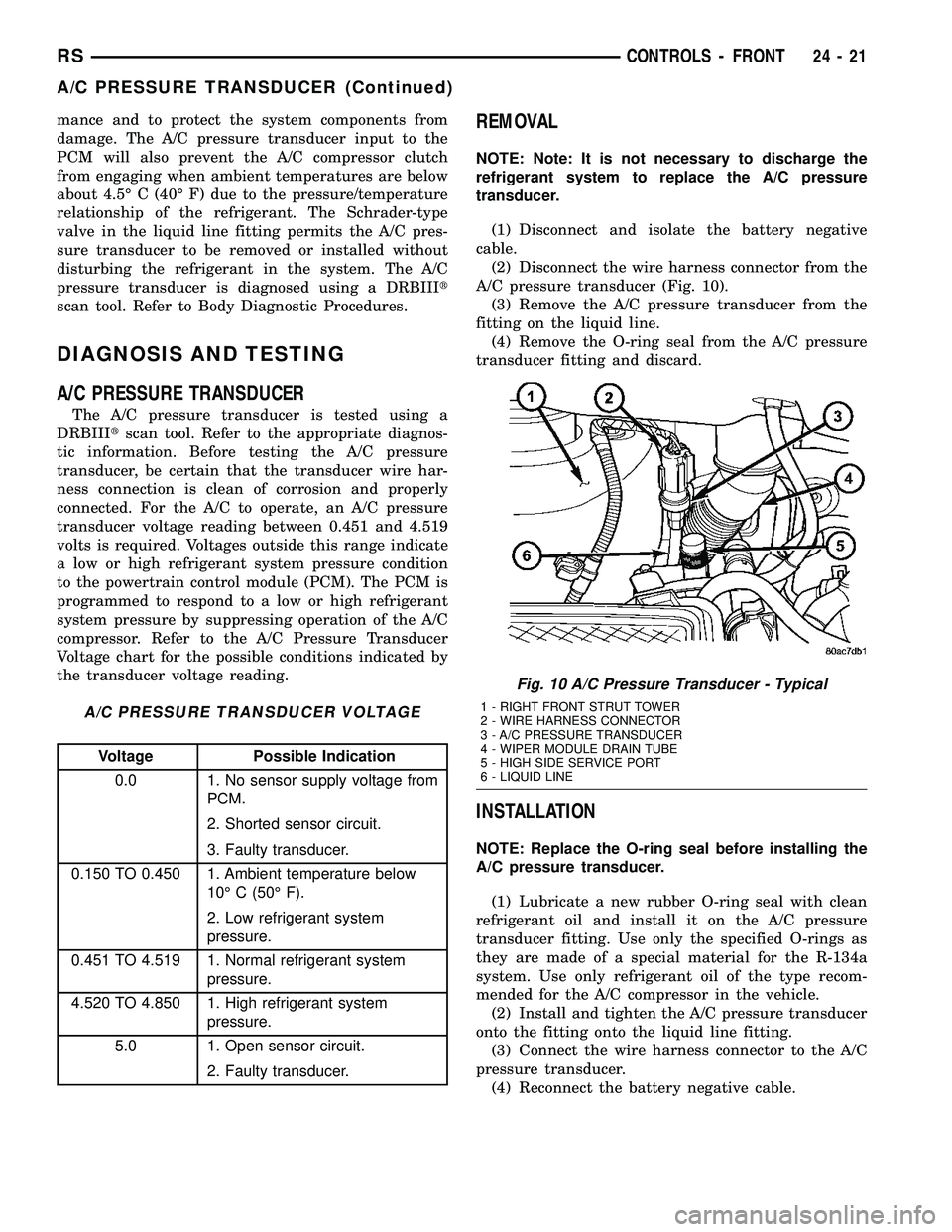
A/C pressure transducer (Fig. 10).
(3) Remove the A/C pressure transducer from the
fitting on the liquid line.
(4) Remove the O-ring seal from the A/C pressure
transducer fitting and discard.
INSTALLATION
NOTE: Replace the O-ring seal before installing the
A/C pressure transducer.
(1) Lubricate a new rubber O-ring seal with clean
refrigerant oil and install it on the A/C pressure
transducer fitting. Use only the specified O-rings as
they are made of a special material for the R-134a
system. Use only refrigerant oil of the type recom-
mended for the A/C compressor in the vehicle.
(2) Install and tighten the A/C pressure transducer
onto the fitting onto the liquid line fitting.
(3) Connect the wire harness connector to the A/C
pressure transducer.
(4) Reconnect the battery negative cable.
Fig. 10 A/C Pressure Transducer - Typical
1 - RIGHT FRONT STRUT TOWER
2 - WIRE HARNESS CONNECTOR
3 - A/C PRESSURE TRANSDUCER
4 - WIPER MODULE DRAIN TUBE
5 - HIGH SIDE SERVICE PORT
6 - LIQUID LINE
RSCONTROLS - FRONT24-21
A/C PRESSURE TRANSDUCER (Continued)
Page 2177 of 2339
(4) Install the glove box (Refer to 23 - BODY/IN-
STRUMENT PANEL/GLOVE BOX - INSTALLA-
TION).
(5) Reconnect the battery negative cable.
EVAPORATOR TEMPERATURE
SENSOR
DESCRIPTION
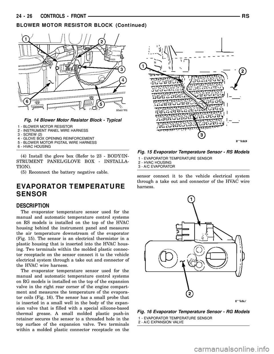
The evaporator temperature sensor used for the
manual and automatic temperature control systems
on RS models is installed on the top of the HVAC
housing behind the instrument panel and measures
the air temperature downstream of the evaporator
(Fig. 15). The sensor is an electrical thermistor in a
plastic housing that is inserted into the HVAC hous-
ing. Two terminals within the molded plastic connec-
tor receptacle on the sensor connect it to the vehicle
electrical system through a take out and connector of
the HVAC wire harness.
The evaporator temperature sensor used for the
manual and automatic temperature control systems
on RG models is installed on the top of the expansion
valve in the right rear corner of the engine compart-
ment and measures the temperature of the evapora-
tor coils (Fig. 16). The sensor has a small probe that
is inserted in a small well in the body of the expan-
sion valve that is filled with a special silicone-based
thermal grease. A small molded plastic push-in
retainer secures the sensor to a threaded hole in the
top surface of the expansion valve. Two terminals
within a molded plastic connector receptacle on thesensor connect it to the vehicle electrical system
through a take out and connector of the HVAC wire
harness.
Fig. 14 Blower Motor Resistor Block - Typical
1 - BLOWER MOTOR RESISTOR
2 - INSTRUMENT PANEL WIRE HARNESS
3 - SCREW (2)
4 - GLOVE BOX OPENING REINFORCEMENT
5 - BLOWER MOTOR PIGTAIL WIRE HARNESS
6 - HVAC HOUSING
Fig. 15 Evaporator Temperature Sensor - RS Models
1 - EVAPORATOR TEMPERATURE SENSOR
2 - HVAC HOUSING
3 - A/C EVAPORATOR
Fig. 16 Evaporator Temperature Sensor - RG Models
1 - EVAPORATOR TEMPERATURE SENSOR
2 - A/C EXPANSION VALVE
24 - 26 CONTROLS - FRONTRS
BLOWER MOTOR RESISTOR BLOCK (Continued)
Page 2188 of 2339
²The normally open terminal (87) provides a bat-
tery current output to the blower motor resistor
(manual heater-A/C control) or blower power module
(ATC heater-A/C control) through a fuse in the IPM
on the fused rear blower motor relay output circuit
only when the blower motor relay coil is energized.
²The normally closed terminal (87A) is not con-
nected to any circuit in this application, but provides
a battery current output only when the rear blower
motor relay coil is de-energized.
Refer to the appropriate wiring information for
diagnosis and testing of the micro-relay and for com-
plete HVAC wiring diagrams.
REMOVAL
(1) Disconnect and isolate the negative battery
cable.
(2) Remove the cover from the integrated power
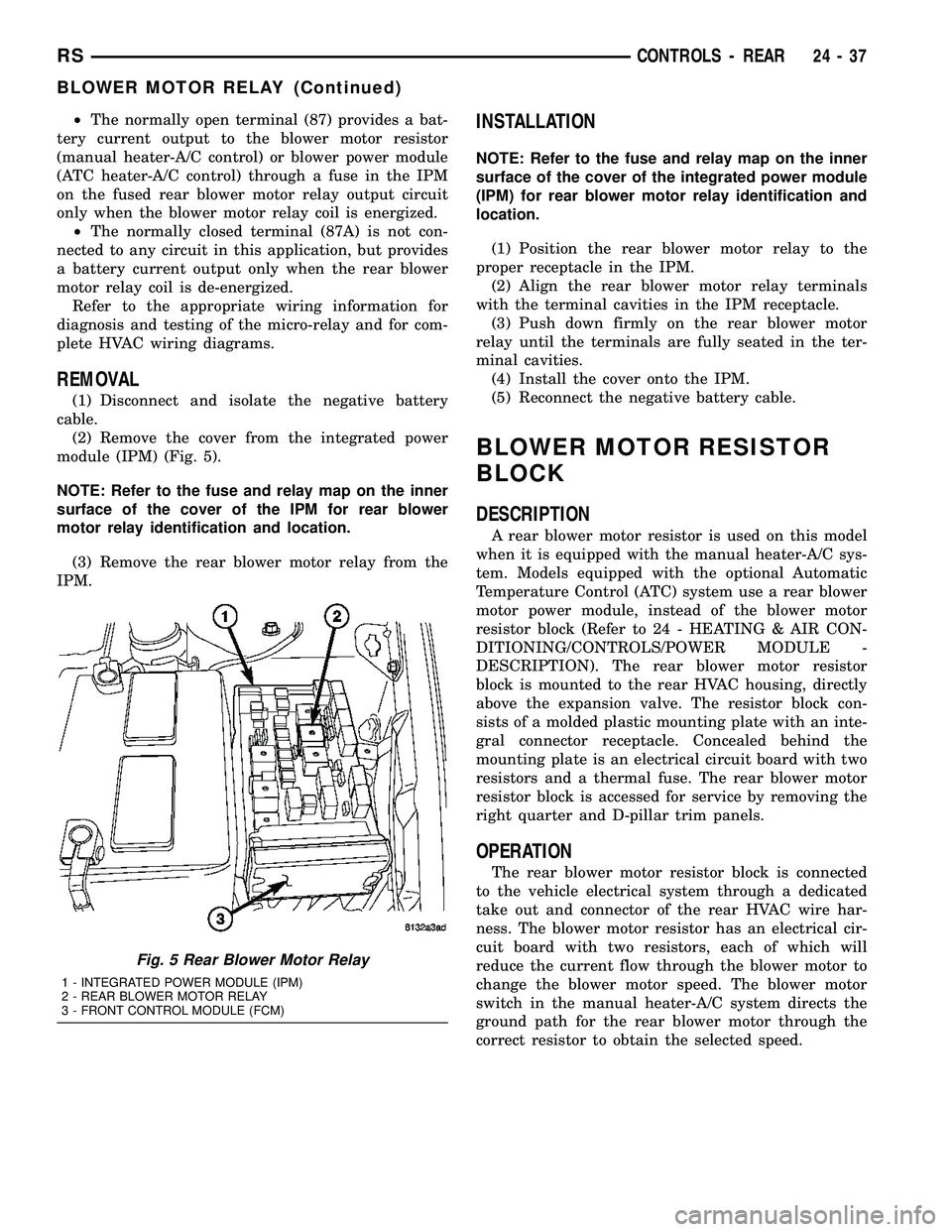
module (IPM) (Fig. 5).
NOTE: Refer to the fuse and relay map on the inner
surface of the cover of the IPM for rear blower
motor relay identification and location.
(3) Remove the rear blower motor relay from the
IPM.
INSTALLATION
NOTE: Refer to the fuse and relay map on the inner
surface of the cover of the integrated power module
(IPM) for rear blower motor relay identification and
location.
(1) Position the rear blower motor relay to the
proper receptacle in the IPM.
(2) Align the rear blower motor relay terminals
with the terminal cavities in the IPM receptacle.
(3) Push down firmly on the rear blower motor
relay until the terminals are fully seated in the ter-
minal cavities.
(4) Install the cover onto the IPM.
(5) Reconnect the negative battery cable.
BLOWER MOTOR RESISTOR
BLOCK
DESCRIPTION
A rear blower motor resistor is used on this model
when it is equipped with the manual heater-A/C sys-
tem. Models equipped with the optional Automatic
Temperature Control (ATC) system use a rear blower
motor power module, instead of the blower motor
resistor block (Refer to 24 - HEATING & AIR CON-
DITIONING/CONTROLS/POWER MODULE -
DESCRIPTION). The rear blower motor resistor
block is mounted to the rear HVAC housing, directly
above the expansion valve. The resistor block con-
sists of a molded plastic mounting plate with an inte-
gral connector receptacle. Concealed behind the
mounting plate is an electrical circuit board with two
resistors and a thermal fuse. The rear blower motor
resistor block is accessed for service by removing the
right quarter and D-pillar trim panels.
OPERATION
The rear blower motor resistor block is connected
to the vehicle electrical system through a dedicated
take out and connector of the rear HVAC wire har-
ness. The blower motor resistor has an electrical cir-
cuit board with two resistors, each of which will
reduce the current flow through the blower motor to
change the blower motor speed. The blower motor
switch in the manual heater-A/C system directs the
ground path for the rear blower motor through the
correct resistor to obtain the selected speed.
Fig. 5 Rear Blower Motor Relay
1 - INTEGRATED POWER MODULE (IPM)
2 - REAR BLOWER MOTOR RELAY
3 - FRONT CONTROL MODULE (FCM)
RSCONTROLS - REAR24-37
BLOWER MOTOR RELAY (Continued)
Page 2217 of 2339
A/C SYSTEM
WARNING: THE AIR CONDITIONING SYSTEM CON-
TAINS REFRIGERANT UNDER HIGH PRESSURE.
SEVERE PERSONAL INJURY MAY RESULT FROM
IMPROPER SERVICE PROCEDURES. REPAIRS
SHOULD ONLY BE PERFORMED BY QUALIFIED
SERVICE PERSONNEL.
AVOID BREATHING THE REFRIGERANT AND
REFRIGERANT OIL VAPOR OR MIST. EXPOSURE
MAY IRRITATE THE EYES, NOSE, AND/OR THROAT.
WEAR EYE PROTECTION WHEN SERVICING THE
AIR CONDITIONING REFRIGERANT SYSTEM. SERI-
OUS EYE INJURY CAN RESULT FROM DIRECT
CONTACT WITH THE REFRIGERANT. IF EYE CON-
TACT OCCURS, SEEK MEDICAL ATTENTION IMME-
DIATELY.
DO NOT EXPOSE THE REFRIGERANT TO OPEN
FLAME. POISONOUS GAS IS CREATED WHEN
REFRIGERANT IS BURNED. AN ELECTRONIC LEAK
DETECTOR IS RECOMMENDED.
IF ACCIDENTAL SYSTEM DISCHARGE OCCURS,
VENTILATE THE WORK AREA BEFORE RESUMING
SERVICE. LARGE AMOUNTS OF REFRIGERANT
RELEASED IN A CLOSED WORK AREA WILL DIS-
PLACE THE OXYGEN AND CAUSE SUFFOCATION.
THE EVAPORATION RATE OF R-134a REFRIGER-
ANT AT AVERAGE TEMPERATURE AND ALTITUDE
IS EXTREMELY HIGH. AS A RESULT, ANYTHING
THAT COMES IN CONTACT WITH THE REFRIGER-
ANT WILL FREEZE. ALWAYS PROTECT THE SKIN
OR DELICATE OBJECTS FROM DIRECT CONTACT
WITH THE REFRIGERANT.
THE R-134a SERVICE EQUIPMENT OR THE VEHI-
CLE REFRIGERANT SYSTEM SHOULD NOT BE
PRESSURE TESTED OR LEAK TESTED WITH COM-
PRESSED AIR. SOME MIXTURES OF AIR AND
R-134a HAVE BEEN SHOWN TO BE COMBUSTIBLE
AT ELEVATED PRESSURES. THESE MIXTURES ARE
POTENTIALLY DANGEROUS, AND MAY RESULT IN
FIRE OR EXPLOSION CAUSING INJURY OR PROP-
ERTY DAMAGE.
CAUTION - A/C SYSTEM
CAUTION: Liquid refrigerant is corrosive to metal
surfaces. Follow the operating instructions supplied
with the service equipment being used.
Never add R-12 to a refrigerant system designed to
use R-134a and do not use R-12 equipment or parts
on the R-134a system. Damage to the system will
result.
R-12 refrigerant oil must not be mixed with R-134a
refrigerant oil. They are not compatible and damage
to the system will result.Do not overcharge the refrigerant system. Over-
charging will cause excessive compressor head
pressure and can cause noise and system failure.
Recover the refrigerant before opening any fitting
or connection. Open the fittings with caution, even
after the system has been discharged. Never open
or loosen a connection before recovering the refrig-
erant.
If equipped, do not remove the secondary retention
clip from any spring-lock coupler connection while
the refrigerant system is under pressure. Recover
the refrigerant before removing the secondary
retention clip. Open the fittings with caution, even
after the system has been discharged. Never open
or loosen a connection before recovering the refrig-
erant.
Do not open the refrigerant system or uncap a
replacement component until you are ready to ser-
vice the system. This will prevent contamination in
the system. Before disconnecting a component,
clean the outside of the fittings thoroughly to pre-
vent contamination from entering the refrigerant
system. Immediately after disconnecting a compo-
nent from the refrigerant system, seal the open fit-
tings with a cap or plug.
Refrigerant oil will absorb moisture from the atmo-
sphere if left uncapped. Do not open a container of
refrigerant oil until you are ready to use it. Replace
the cap on the oil container immediately after using.
Store refrigerant oil only in a clean, airtight, and
moisture-free container.
Keep service tools and the work area clean. Con-
tamination of the refrigerant system must be
avoided.
CAUTION: The use of A/C system sealers may
result in damage to A/C refrigerant recovery/evacu-
ation/recharging equipment and/or A/C systems.
Many federal, state/provincial and local regulations
prohibit the recharge of A/C systems with known
leaks. DaimlerChrysler recommends the detection
of A/C system leaks through the use of approved
leak detectors and fluorescent leak detection dyes.
Vehicles found with A/C system sealers should be
treated as contaminated and replacement of the
entire A/C refrigerant system is recommended. A/C
systems found to be contaminated with A/C system
sealers, A/C stop-leak products or seal conditioners
voids the warranty for the A/C system.
24 - 66 PLUMBING - FRONTRS
PLUMBING - FRONT (Continued)
Page 2218 of 2339
DIAGNOSIS AND TESTING
REFRIGERANT SYSTEM LEAKS
WARNING: R-134a SERVICE EQUIPMENT OR VEHI-
CLE A/C SYSTEM SHOULD NOT BE PRESSURE
TESTED OR LEAK TESTED WITH COMPRESSED
AIR. MIXTURE OF AIR and R-134a CAN BE COMBUS-
TIBLE AT ELEVATED PRESSURES. THESE MIX-
TURES ARE POTENTIALLY DANGEROUS AND MAY
RESULT IN FIRE OR EXPLOSION CAUSING INJURY
OR PROPERTY DAMAGE.
AVOID BREATHING A/C REFRIGERANT AND LUBRI-
CANT VAPOR OR MIST. EXPOSURE MAY IRRITATE
EYES, NOSE AND THROAT. USE ONLY APPROVED
SERVICE EQUIPMENT MEETING SAE REQUIRE-
MENTS TO DISCHARGE R-134a SYSTEM. IF ACCI-
DENTAL SYSTEM DISCHARGE OCCURS, VENTILATE
WORK AREA BEFORE RESUMING SERVICE.
If the A/C system is not cooling properly, determine
if the refrigerant system is fully charged with R-134a
(Refer to 24 - HEATING & AIR CONDITIONING/
PLUMBING - FRONT/REFRIGERANT - DIAGNO-
SIS AND TESTING - REFRIGERANT SYSTEM
CHARGE LEVEL). If while performing this test A/C
liquid line pressure is less than 345 kPa (50 psi) pro-
ceed to System Empty procedure. If liquid line pres-
sure is greater than 345 kPa (50 psi) proceed to
System Low procedure. If the refrigerant system is
empty or low in refrigerant charge, a leak at any line
fitting or component seal is likely. A review of the fit-
tings, lines and components for oily residue is an
indication of the leak location.
To detect a leak in the refrigerant system, perform
one of the following procedures as indicated by the
results of the refrigerant system charge level test.
SYSTEM EMPTY
(1) Evacuate the refrigerant system to the lowest
degree of vacuum possible (approx. 28 in Hg.) (Refer
to 24 - HEATING & AIR CONDITIONING/PLUMB-
ING - FRONT/REFRIGERANT - STANDARD PRO-
CEDURE - REFRIGERANT SYSTEM EVACUATE).
Determine if the system holds a vacuum for 15 min-
utes. If vacuum is held, a leak is probably not
present. If system will not maintain vacuum level,
proceed with this procedure.
(2) Prepare a 0.284 Kg. (10 oz.) refrigerant charge
to be injected into the system.
(3) Connect and dispense 0.284 Kg. (10 oz.) of
refrigerant into the evacuated refrigerant system
(Refer to 24 - HEATING & AIR CONDITIONING/
PLUMBING - FRONT/REFRIGERANT - STANDARD
PROCEDURE - REFRIGERANT SYSTEM CHARGE).
(4) Proceed to the SYSTEM LOW procedures.SYSTEM LOW
(1) Position the vehicle in a wind-free work area.
This will aid in detecting small leaks.
(2) Bring the refrigerant system up to operating
temperature and pressure. This is done by allowing
the engine to run for five minutes with the system
set to the following:
²Transaxle in Park
²Engine idling
²Rear A/C Off (if equipped)
²A/C controls set to 100 percent outside air
²Blower switch in the highest speed position
²A/C in the ON position
²Front windows open
CAUTION: A leak detector designed for R-12 refrig-
erant (only) will not detect leaks in a R-134a refrig-
erant system.
(3) Shut off the vehicle and wait 2 to 7 minutes.
Then use an Electronic Leak Detector that is
designed to detect R-134a type refrigerant and search
for leaks. Fittings, lines, or components that appear
to be oily usually indicates a refrigerant leak. To
inspect the evaporator core for leaks, insert the leak
detector probe into the drain tube opening or a heat
duct. A R-134a dye is available to aid in leak detec-
tion, use only DaimlerChrysler approved refrigerant
dye.
SYSTEM CHARGE LEVEL TEST
WARNING: REFER TO THE APPLICABLE WARN-
INGS AND CAUTIONS FOR THIS SYSTEM BEFORE
PERFORMING THE FOLLOWING OPERATION (Refer
to 24 - HEATING & AIR CONDITIONING/PLUMBING -
FRONT - WARNING - A/C PLUMBING) and (Refer to
24 - HEATING & AIR CONDITIONING/PLUMBING -
FRONT - CAUTION - A/C PLUMBING).
NOTE: Always refer to the underhood HVAC Speci-
fication Label for the refrigerant fill specification of
the vehicle being serviced.
The procedure that follows should be used to deter-
mine whether the refrigerant system contains the
proper refrigerant charge. Symptoms of an improper
refrigerant charge (low) include: poor air conditioner
performance, fog emitted from the air conditioner
outlets, a hissing sound from the expansion valve/
evaporator area. There are two different methods
with which the refrigerant charge level may be
tested:
1. Using a DRBIIItscan tool, a thermocouple and
the Charge Determination Chart (Fig. 1). Refer to
the appropriate diagnostic information.
RSPLUMBING - FRONT24-67
PLUMBING - FRONT (Continued)
Page 2220 of 2339
(4) Raise the liquid line (discharge) pressure to
about 1793 kPa (260 psi) by placing a piece of card-
board over part of the front side of the condenser. To
place the cardboard properly, remove the upper radi-
ator sight shield from the front fascia. Cover only
enough of the condenser to raise and maintain the
liquid line pressure at the specified level.
(5) Observe the liquid line (discharge) pressure
and liquid line temperature. Using the Charge Deter-
mination Chart (Fig. 1), determine whether the
refrigerant system is operating within the Proper
Charge Range.
(a) If the refrigerant system is operating in the
Undercharged area of the chart, add 0.057 kilo-
gram (0.125 pound or 2 ounces) of refrigerant to
the system.
(b) If the refrigerant system is operating in the
Overcharged area of the chart, reclaim 0.057 kilo-
gram (0.125 pound or 2 ounces) of refrigerant from
the system.
(6) Recheck the system charge level following each
refrigerant adjustment. Continue this process until
the system readings are in the Proper Charge Range
area on the Charge Determination Chart.
STANDARD PROCEDURE
HANDLING TUBING AND FITTINGS
CAUTION: The system must be completely empty
before opening any fitting or connection in the
refrigeration system. Open fittings with caution
even after the system has been emptied. If any
pressure is noticed as a fitting is loosened,
retighten fitting and evacuate the system again.
A good rule for the flexible hose lines is to keep the
radius of all bends at least 10 times the diameter of
the hose. Sharper bends will reduce the flow of
refrigerant. The flexible hose lines should be routed
so they are at least 3 inches (80 mm) from the
exhaust manifold. Inspect all flexible hose lines to
make sure they are in good condition and properly
routed.
The use of correct wrenches when making connec-
tions is very important. Improper wrenches or
improper use of wrenches can damage the fittings.
The internal parts of the A/C system will remain sta-
ble as long as moisture-free refrigerant and refrig-
erant oil is used. Abnormal amounts of dirt,
moisture or air can upset the chemical stability.
This may cause operational troubles or even seri-
ous damage if present in more than very small
quantities. Before disconnecting a component,
clean the outside of the fittings thoroughly to pre-
vent contamination from entering the refrigerant
system.When opening a refrigeration system, have every-
thing you will need to repair the system ready. This
will minimize the amount of time the system must
be opened. Cap or plug all lines and fittings as
soon as they are opened. This will help prevent the
entrance of dirt and moisture. All new lines and
components should be capped or sealed until they
are ready to be used. Before connecting a compo-
nent, clean the outside of the fittings thoroughly to
prevent contamination from entering the refrigerant
system.
All tools, including the refrigerant dispensing mani-
fold, the manifold gauge set, and test hoses should
be kept clean and dry.
Kinks in the refrigerant tubing or sharp bends in
the refrigerant hose lines will greatly reduce the
capacity of the entire system. High pressures are pro-
duced in the system when it is operating. Extreme
care must be exercised to make sure that all connec-
tions are pressure tight. Dirt and moisture can enter
the system when it is opened for repair or replace-
ment of lines or components. The refrigerant oil will
absorb moisture readily out of the air. This moisture
will convert into acids within a closed system.
REFRIGERANT SYSTEM SERVICE EQUIPMENT
WARNING: EYE PROTECTION MUST BE WORN
WHEN SERVICING AN AIR CONDITIONING REFRIG-
ERANT SYSTEM. TURN OFF (ROTATE CLOCKWISE)
ALL VALVES ON THE EQUIPMENT BEING USED
BEFORE CONNECTING TO, OR DISCONNECTING
FROM THE REFRIGERANT SYSTEM. FAILURE TO
OBSERVE THESE WARNINGS MAY RESULT IN PER-
SONAL INJURY.
WARNING: REVIEW THE WARNINGS AND CAU-
TIONS IN THE FRONT OF THIS SECTION BEFORE
PERFORMING THE FOLLOWING OPERATION (Refer
to 24 - HEATING & AIR CONDITIONING/PLUMBING -
WARNING) and (Refer to 24 - HEATING & AIR CON-
DITIONING/PLUMBING - CAUTION).
RECOVERY/RECYCLING STATION
When servicing the air conditioning system, a
R-134a refrigerant recovery/recycling/charging sta-
tion that meets SEA Standard J2210 must be used
(Fig. 2). Contact an automotive service equipment
supplier for refrigerant recovery/recycling/charging
equipment. See the operating instructions supplied
by the equipment manufacturer for proper care and
use of this equipment.
RSPLUMBING - FRONT24-69
PLUMBING - FRONT (Continued)