Page 55 of 420

•TheBelt Tension Sensor (BTS)is located at the
outboard passenger lap belt anchor. The BTS generates
a signal based on outboard lap belt tension. This signal
is sent to the OCM to ensure that the resultant bladder
pressure increase due to applied lap belt tension does
not cause a small occupant to be classified as a larger
occupant.
•TheBladder Assemblyis located beneath the seat
cushion foam. The pressure sensor sends a signal to
the OCM.
The front passenger seat assembly contains critical com-
ponents that affect the front passenger airbag deploy-
ment. Correctly functioning front passenger seat compo-
nents are critical for the Occupant Classification System
(OCS) to properly classify the front passenger and calcu-
late the proper airbag deployment. Do not make any
modifications to the front passenger seat components,
assembly, or to the seat cover.
WARNING!
Unapproved modifications or service procedures to
the front passenger seat assembly, its related compo-
nents, or seat cover may inadvertently change the
airbag deployment in case of a frontal crash. This
could result in death or serious injury to the front
seat passenger if the vehicle is involved in an acci-
dent. A modified vehicle may not comply with
required Federal Motor Vehicle Safety Standards
(FMVSS).
The following requirements must be strictly adhered to:
•Do not modify the front passenger seat assembly or
components in any way.
•Do not modify the front seat center console or center
position seat in any way.
THINGS TO KNOW BEFORE STARTING YOUR VEHICLE 55
2
Page 106 of 420
The controls for the second row heated seats are located
on the center console between the seats. Press the switch
once to select a heat setting (high or low) and press the
switch a second time in the same direction to turn the
heated seat off. The indicator light will show when LOW
or HIGH heat is ON.NOTE:
•If the lights in the second row heated seat switch begin
to flash when the switch is pressed, it indicates that the
heated seat is not functioning properly and that ser-
vice is required. See your authorized dealer for service.
•Once a heat setting is selected, heat will be felt within
2 to 3 minutes.
•The heated seats will turn off when the ignition switch
is turned to the OFF position.
Rear Heated Seat Switches
106 UNDERSTANDING THE FEATURES OF YOUR VEHICLE
Page 114 of 420

WARNING!
•Not all head restraints in this vehicle are the same.
Head restraints from one seating position should not
be removed and installed in any other seating posi-
tion. In a collision, serious injury or death may result
if the proper head restraint is not installed on each
seat.
•The cargo area in the rear of the vehicle should not
be used as a play area by children. They could be
seriously injured in a collision. Children should be
seated and using the proper restraint system.
•It is extremely dangerous to ride in a cargo area,
inside or outside of a vehicle. In a collision, people
riding in these areas are more likely to be seriously
injured or killed.
•Do not allow people to ride in any area of your
vehicle that is not equipped with seats and seat belts.
•Be sure everyone in your vehicle is in a seat and
using a seat belt properly.
Load Floor—If Equipped
For additional cargo space, the second and third row
seatbacks may be folded forward and the load floor
extended to cover the center console.
To extend the load floor, follow these steps:
1. Move the second row seats to the full rear position.
2. Fold the second and third row seatbacks down.
3. Pull on the load floor strap and lift the panel from the
driver’s second row seatback over the center console and
onto the passenger second row seat.
114 UNDERSTANDING THE FEATURES OF YOUR VEHICLE
Page 130 of 420
TRACTION CONTROL SWITCH—IF EQUIPPED
The traction control Indicator, located in the instrument
cluster, will light up when the Traction Control is in use.
To turn the system OFF, press the Traction Control switch
located on center console next to the ash tray, until the
traction control Indicator in the instrument cluster lights
up.
To turn the system back ON, press the switch a second
time until the traction control Indicator turns OFF.
NOTE:
•The traction control Indicator comes on each time the
ignition switch is turned ON. This will occur even if
you used the switch to turn the system OFF.
Traction Control Switch
130 UNDERSTANDING THE FEATURES OF YOUR VEHICLE
Page 149 of 420
A third outlet is located on the back of the front center
console near the floor, and is also controlled by the
ignition switch.
A fourth outlet is located on the driver’s side, in the rear
cargo area and is also controlled by the ignition switch.The outlets include tethered caps labeled with a key or
battery symbol indicating the power source. The passen-
ger side instrument panel and center console outlets are
powered directly from the battery, items plugged into
these outlets may discharge the battery and/or prevent
engine starting.
The passenger side and center console outlets are pro-
tected by an automatic reset circuit breaker. The auto-
matic circuit breaker restores power when the overload is
removed.
NOTE:If desired, the fourth power outlet in the rear
cargo area can be converted by your authorized dealer to
provide power with the ignition switch in the OFF
position.
Front Power Outlets
UNDERSTANDING THE FEATURES OF YOUR VEHICLE 149
3
Page 150 of 420

Electrical Outlet Use With Engine Off
CAUTION!
•Many accessories that can be plugged in draw power from
the vehicle’s battery, even when not in use (i.e. cellular
phones, etc.). Eventually, if plugged in long enough, the
vehicle’s battery will discharge sufficiently to degrade
battery life and/or prevent engine starting.
•Accessories that draw higher power (i.e. coolers, vacuum
cleaners, lights, etc.), will degrade the battery even more
quickly. Only use these intermittently and with greater
caution.
•After the use of high power draw accessories, or long
periods of the vehicle not being started (with accessories
still plugged in), the vehicle must be driven a sufficient
length of time to allow the alternator to recharge the
vehicle’s battery.
•Power outlets are designed for accessory plugs only. Do not
hang any type of accessory or accessory bracket from the
plug. Improper use of the power outlet can cause damage.
CUPHOLDERS
Front Seat Cupholders
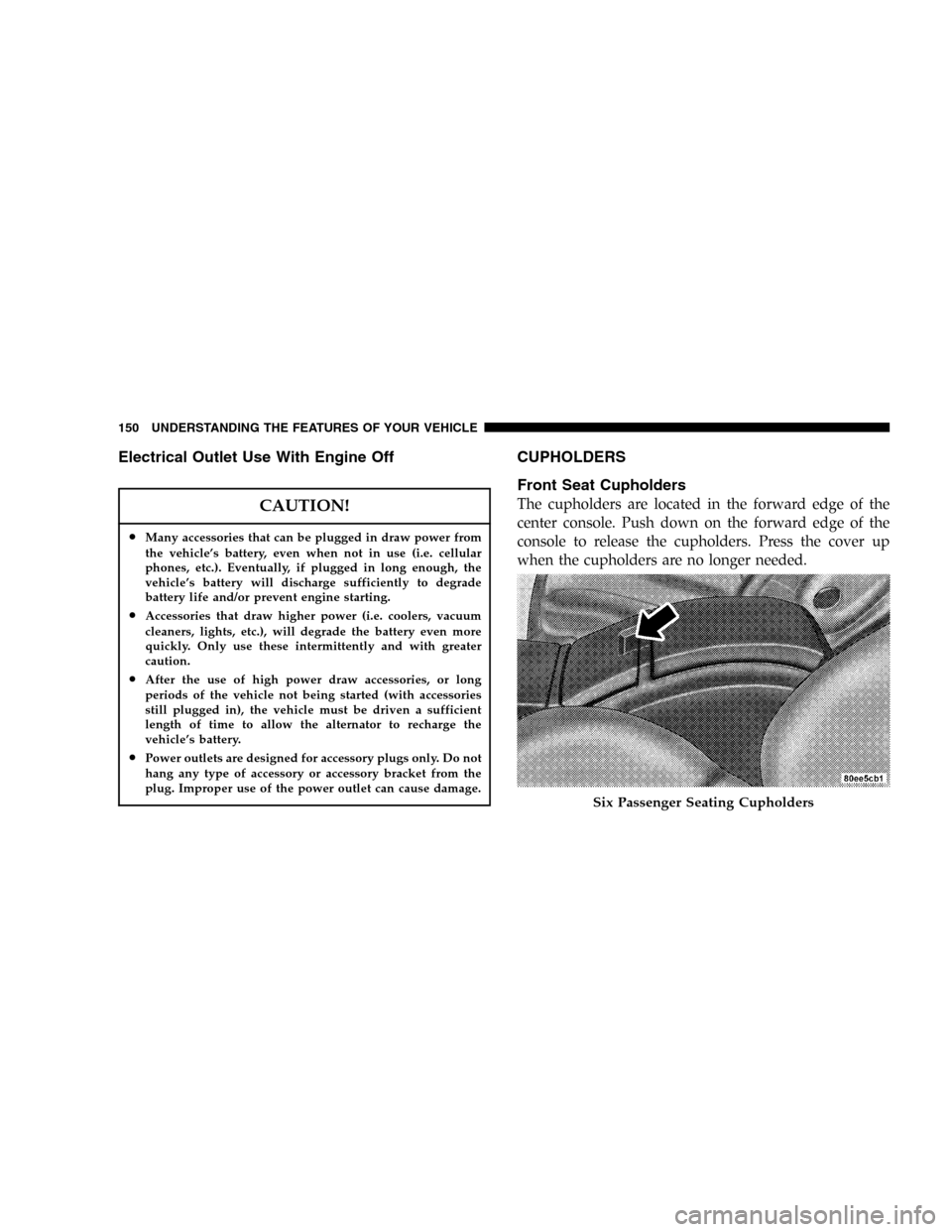
The cupholders are located in the forward edge of the
center console. Push down on the forward edge of the
console to release the cupholders. Press the cover up
when the cupholders are no longer needed.
Six Passenger Seating Cupholders
150 UNDERSTANDING THE FEATURES OF YOUR VEHICLE
Page 151 of 420

Second Row Seat Cupholders
On vehicles equipped with five passenger seating the
second row seat cupholders are located in middle of the
seatback armrest. Pull down on the armrest to access the
cupholders. Push the armrest up when the cupholders
are no longer needed.On vehicles equipped with six passenger seating the
second row seat cupholders are located in the forward
edge of the center console located between the second
row seats. Push down on the forward edge of the console
to release the cupholders. Press the cover up when the
cupholders are no longer needed.
Third Row Seat Cupholders—If Equipped
There are cupholders located in each rear trim panel for
the third row seat passengers.
STORAGE
Console Features
The center consoles may be equipped with a tissue
holder mounted on the underside of the cover. The
bottom of the console bins may also have built in holders
for compact discs or cassette tapes.
Five Passenger Seating Cupholders
UNDERSTANDING THE FEATURES OF YOUR VEHICLE 151
3
Page 241 of 420

The recirculation control is now programmed so that the
recirculation mode willnotreset to the outside air mode
when the engine is restarted. The recirculation program-
ming can be changed back by repeating this procedure.
Rear Fan Operation
To operate the rear fan, press the�REAR�button. The first
time this button is pressed the�REAR AUTO�display
will illuminate indicating that the rear fan speed is
automatically controlled. To manually control the rear
fan speed, press the�REAR�button again and only
�REAR�will illuminate in the display. This allows the rear
seat occupants to control the rear fan speed using the
switch located in the center console between the second
row seats. By pressing the�REAR�button a third time,
the rear fan will shut off.
When the ATC display reads�REAR AUTO�or when the
rear fan is off, the switch located in the center console
between the second row seats is not functional. When theATC display reads�REAR�, only the rear seat occupants
can control the rear fan speed from the rear switch. When
in the“REAR”mode, the rear occupants can set the rear
switch to any fan speed including�OFF�,or�AUTO�.
While in the�AUTO�position, the rear fan speed will be
automatically controlled.
Summer Operation
The engine cooling system in air conditioned vehicles
must be protected with a high-quality antifreeze coolant
to provide proper corrosion protection and to protect
against engine overheating. A 50% solution of ethylene
glycol antifreeze coolant in water is recommended. Refer
to section 7, Maintenance Procedures, of this manual for
proper coolant selection.
UNDERSTANDING YOUR INSTRUMENT PANEL 241
4