2005 CHRYSLER CARAVAN check oil
[x] Cancel search: check oilPage 1260 of 2339
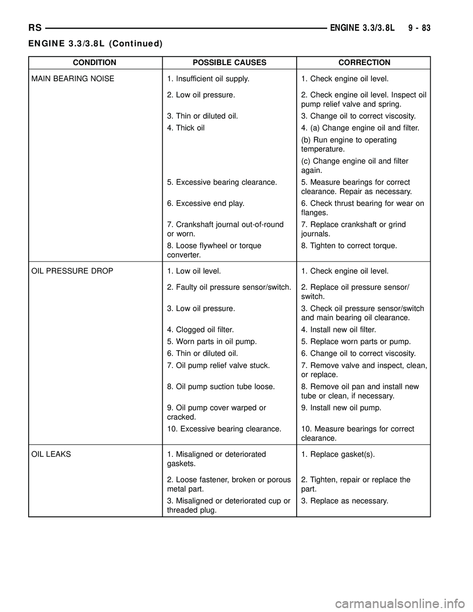
CONDITION POSSIBLE CAUSES CORRECTION
MAIN BEARING NOISE 1. Insufficient oil supply. 1. Check engine oil level.
2. Low oil pressure. 2. Check engine oil level. Inspect oil
pump relief valve and spring.
3. Thin or diluted oil. 3. Change oil to correct viscosity.
4. Thick oil 4. (a) Change engine oil and filter.
(b) Run engine to operating
temperature.
(c) Change engine oil and filter
again.
5. Excessive bearing clearance. 5. Measure bearings for correct
clearance. Repair as necessary.
6. Excessive end play. 6. Check thrust bearing for wear on
flanges.
7. Crankshaft journal out-of-round
or worn.7. Replace crankshaft or grind
journals.
8. Loose flywheel or torque
converter.8. Tighten to correct torque.
OIL PRESSURE DROP 1. Low oil level. 1. Check engine oil level.
2. Faulty oil pressure sensor/switch. 2. Replace oil pressure sensor/
switch.
3. Low oil pressure. 3. Check oil pressure sensor/switch
and main bearing oil clearance.
4. Clogged oil filter. 4. Install new oil filter.
5. Worn parts in oil pump. 5. Replace worn parts or pump.
6. Thin or diluted oil. 6. Change oil to correct viscosity.
7. Oil pump relief valve stuck. 7. Remove valve and inspect, clean,
or replace.
8. Oil pump suction tube loose. 8. Remove oil pan and install new
tube or clean, if necessary.
9. Oil pump cover warped or
cracked.9. Install new oil pump.
10. Excessive bearing clearance. 10. Measure bearings for correct
clearance.
OIL LEAKS 1. Misaligned or deteriorated
gaskets.1. Replace gasket(s).
2. Loose fastener, broken or porous
metal part.2. Tighten, repair or replace the
part.
3. Misaligned or deteriorated cup or
threaded plug.3. Replace as necessary.
RSENGINE 3.3/3.8L9-83
ENGINE 3.3/3.8L (Continued)
Page 1261 of 2339
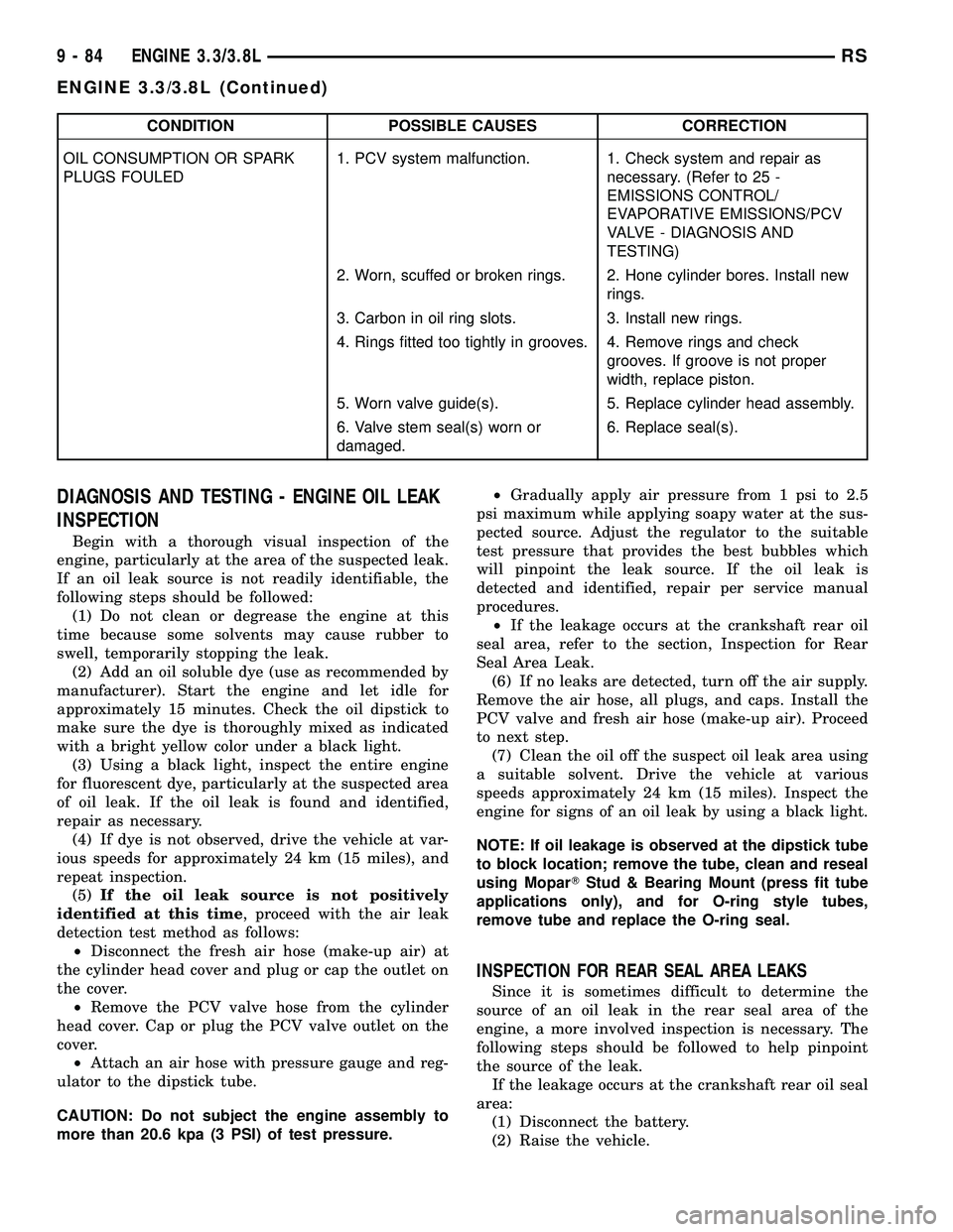
CONDITION POSSIBLE CAUSES CORRECTION
OIL CONSUMPTION OR SPARK
PLUGS FOULED1. PCV system malfunction. 1. Check system and repair as
necessary. (Refer to 25 -
EMISSIONS CONTROL/
EVAPORATIVE EMISSIONS/PCV
VALVE - DIAGNOSIS AND
TESTING)
2. Worn, scuffed or broken rings. 2. Hone cylinder bores. Install new
rings.
3. Carbon in oil ring slots. 3. Install new rings.
4. Rings fitted too tightly in grooves. 4. Remove rings and check
grooves. If groove is not proper
width, replace piston.
5. Worn valve guide(s). 5. Replace cylinder head assembly.
6. Valve stem seal(s) worn or
damaged.6. Replace seal(s).
DIAGNOSIS AND TESTING - ENGINE OIL LEAK
INSPECTION
Begin with a thorough visual inspection of the
engine, particularly at the area of the suspected leak.
If an oil leak source is not readily identifiable, the
following steps should be followed:
(1) Do not clean or degrease the engine at this
time because some solvents may cause rubber to
swell, temporarily stopping the leak.
(2) Add an oil soluble dye (use as recommended by
manufacturer). Start the engine and let idle for
approximately 15 minutes. Check the oil dipstick to
make sure the dye is thoroughly mixed as indicated
with a bright yellow color under a black light.
(3) Using a black light, inspect the entire engine
for fluorescent dye, particularly at the suspected area
of oil leak. If the oil leak is found and identified,
repair as necessary.
(4) If dye is not observed, drive the vehicle at var-
ious speeds for approximately 24 km (15 miles), and
repeat inspection.
(5)If the oil leak source is not positively
identified at this time, proceed with the air leak
detection test method as follows:
²Disconnect the fresh air hose (make-up air) at
the cylinder head cover and plug or cap the outlet on
the cover.
²Remove the PCV valve hose from the cylinder
head cover. Cap or plug the PCV valve outlet on the
cover.
²Attach an air hose with pressure gauge and reg-
ulator to the dipstick tube.
CAUTION: Do not subject the engine assembly to
more than 20.6 kpa (3 PSI) of test pressure.²Gradually apply air pressure from 1 psi to 2.5
psi maximum while applying soapy water at the sus-
pected source. Adjust the regulator to the suitable
test pressure that provides the best bubbles which
will pinpoint the leak source. If the oil leak is
detected and identified, repair per service manual
procedures.
²If the leakage occurs at the crankshaft rear oil
seal area, refer to the section, Inspection for Rear
Seal Area Leak.
(6) If no leaks are detected, turn off the air supply.
Remove the air hose, all plugs, and caps. Install the
PCV valve and fresh air hose (make-up air). Proceed
to next step.
(7) Clean the oil off the suspect oil leak area using
a suitable solvent. Drive the vehicle at various
speeds approximately 24 km (15 miles). Inspect the
engine for signs of an oil leak by using a black light.
NOTE: If oil leakage is observed at the dipstick tube
to block location; remove the tube, clean and reseal
using MoparTStud & Bearing Mount (press fit tube
applications only), and for O-ring style tubes,
remove tube and replace the O-ring seal.
INSPECTION FOR REAR SEAL AREA LEAKS
Since it is sometimes difficult to determine the
source of an oil leak in the rear seal area of the
engine, a more involved inspection is necessary. The
following steps should be followed to help pinpoint
the source of the leak.
If the leakage occurs at the crankshaft rear oil seal
area:
(1) Disconnect the battery.
(2) Raise the vehicle.
9 - 84 ENGINE 3.3/3.8LRS
ENGINE 3.3/3.8L (Continued)
Page 1262 of 2339
(3) Remove torque converter or clutch housing
cover and inspect rear of block for evidence of oil.
Use a black light to check for the oil leak. If a leak is
present in this area, remove transmission for further
inspection.
(a) Circular spray pattern generally indicates
seal leakage or crankshaft damage.
(b) Where leakage tends to run straight down,
possible causes are a porous block, oil gallery cup
plug, bedplate to cylinder block mating surfaces
and seal bore. See proper repair procedures for
these items.
(4) If no leaks are detected, pressurize the crank-
case as previously described.
CAUTION: Do not exceed 20.6 kPa (3 psi).
(5) If the leak is not detected, very slowly turn the
crankshaft and watch for leakage. If a leak is
detected between the crankshaft and seal while
slowly turning the crankshaft, it is possible the
crankshaft seal surface is damaged. The seal area on
the crankshaft could have minor nicks or scratches
that can be polished out with emery cloth.
CAUTION: Use extreme caution when crankshaft
polishing is necessary to remove minor nicks and
scratches. The crankshaft seal flange is especially
machined to complement the function of the rear oil
seal.
(6) For bubbles that remain steady with shaft
rotation, no further inspection can be done until dis-
assembled.
(7) After the oil leak root cause and appropriate
corrective action have been identified, replace compo-
nent(s) as necessary.
DIAGNOSIS AND TESTING - CYLINDER
COMPRESSION PRESSURE TEST
The results of a cylinder compression pressure test
can be utilized to diagnose several engine malfunc-
tions.
Ensure the battery is completely charged and the
engine starter motor is in good operating condition.
Otherwise the indicated compression pressures may
not be valid for diagnosis purposes.
(1) Check engine oil level and add oil if necessary.
(2) Drive the vehicle until engine reaches normal
operating temperature. Select a route free from traf-
fic and other forms of congestion, observe all traffic
laws, and accelerate through the gears several times
briskly.
(3) Remove all spark plugs from engine. As spark
plugs are being removed, check electrodes for abnor-
mal firing indicators fouled, hot, oily, etc. Record cyl-
inder number of spark plug for future reference.(4) Remove the Auto Shutdown (ASD) relay from
the PDC.
(5) Be sure throttle blade is fully open during the
compression check.
(6) Insert compression gauge adaptor Special Tool
8116 or the equivalent, into the #1 spark plug hole in
cylinder head. Connect the 0±500 psi (Blue) pressure
transducer (Special Tool CH7059) with cable adap-
tors to the DRBIIIt. For Special Tool identification,
(Refer to 9 - ENGINE - SPECIAL TOOLS).
(7) Crank engine until maximum pressure is
reached on gauge. Record this pressure as #1 cylin-
der pressure.
(8) Repeat the previous step for all remaining cyl-
inders.
(9) Compression should not be less than 689 kPa
(100 psi) and not vary more than 25 percent from cyl-
inder to cylinder.
(10) If one or more cylinders have abnormally low
compression pressures, repeat the compression test.
(11) If the same cylinder or cylinders repeat an
abnormally low reading on the second compression
test, it could indicate the existence of a problem in
the cylinder in question.The recommended com-
pression pressures are to be used only as a
guide to diagnosing engine problems. An engine
should not be disassembled to determine the
cause of low compression unless some malfunc-
tion is present.
DIAGNOSIS AND TESTING - CYLINDER
COMBUSTION PRESSURE LEAKAGE TEST
The combustion pressure leakage test provides an
accurate means for determining engine condition.
Combustion pressure leakage testing will detect:
²Exhaust and intake valve leaks (improper seat-
ing).
²Leaks between adjacent cylinders or into water
jacket.
²Any causes for combustion/compression pressure
loss.
WARNING: DO NOT REMOVE THE PRESSURE CAP
WITH THE SYSTEM HOT AND UNDER PRESSURE
BECAUSE SERIOUS BURNS FROM COOLANT CAN
OCCUR.
Check the coolant level and fill as required. DO
NOT install the pressure cap.
Start and operate the engine until it attains nor-
mal operating temperature, then turn the engine
OFF.
Clean spark plug recesses with compressed air.
Remove the spark plugs.
Remove the oil filler cap.
Remove the air cleaner.
RSENGINE 3.3/3.8L9-85
ENGINE 3.3/3.8L (Continued)
Page 1263 of 2339
Calibrate the tester according to the manufactur-
er's instructions. The shop air source for testing
should maintain 483 kPa (70 psi) minimum, 1,379
kPa (200 psi) maximum, with 552 kPa (80 psi) rec-
ommended.
Perform the test procedures on each cylinder
according to the tester manufacturer's instructions.
While testing, listen for pressurized air escaping
through the throttle body, tailpipe and oil filler cap
opening. Check for bubbles in the coolant.
All gauge pressure indications should be equal,
with no more than 25% leakage per cylinder.
FOR EXAMPLE:At 552 kPa (80 psi) input pres-
sure, a minimum of 414 kPa (60 psi) should be main-
tained in the cylinder.
STANDARD PROCEDURE
STANDARD PROCEDURE - MEASURING
BEARING CLEARANCE USING PLASTIGAGE
Engine crankshaft bearing clearances can be deter-
mined by use of Plastigage or equivalent. The follow-
ing is the recommended procedure for the use of
Plastigage:
(1) Remove oil film from surface to be checked.
Plastigage is soluble in oil.
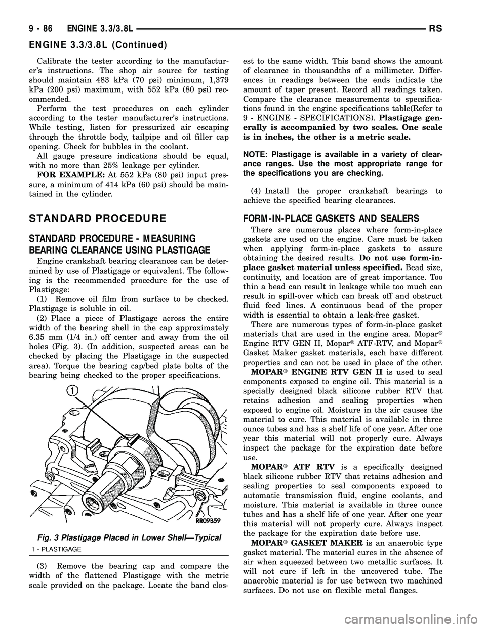
(2) Place a piece of Plastigage across the entire
width of the bearing shell in the cap approximately
6.35 mm (1/4 in.) off center and away from the oil
holes (Fig. 3). (In addition, suspected areas can be
checked by placing the Plastigage in the suspected
area). Torque the bearing cap/bed plate bolts of the
bearing being checked to the proper specifications.
(3) Remove the bearing cap and compare the
width of the flattened Plastigage with the metric
scale provided on the package. Locate the band clos-est to the same width. This band shows the amount
of clearance in thousandths of a millimeter. Differ-
ences in readings between the ends indicate the
amount of taper present. Record all readings taken.
Compare the clearance measurements to specsifica-
tions found in the engine specifications table(Refer to
9 - ENGINE - SPECIFICATIONS).Plastigage gen-
erally is accompanied by two scales. One scale
is in inches, the other is a metric scale.
NOTE: Plastigage is available in a variety of clear-
ance ranges. Use the most appropriate range for
the specifications you are checking.
(4) Install the proper crankshaft bearings to
achieve the specified bearing clearances.
FORM-IN-PLACE GASKETS AND SEALERS
There are numerous places where form-in-place
gaskets are used on the engine. Care must be taken
when applying form-in-place gaskets to assure
obtaining the desired results.Do not use form-in-
place gasket material unless specified.Bead size,
continuity, and location are of great importance. Too
thin a bead can result in leakage while too much can
result in spill-over which can break off and obstruct
fluid feed lines. A continuous bead of the proper
width is essential to obtain a leak-free gasket.
There are numerous types of form-in-place gasket
materials that are used in the engine area. Mopart
Engine RTV GEN II, MopartATF-RTV, and Mopart
Gasket Maker gasket materials, each have different
properties and can not be used in place of the other.
MOPARtENGINE RTV GEN IIis used to seal
components exposed to engine oil. This material is a
specially designed black silicone rubber RTV that
retains adhesion and sealing properties when
exposed to engine oil. Moisture in the air causes the
material to cure. This material is available in three
ounce tubes and has a shelf life of one year. After one
year this material will not properly cure. Always
inspect the package for the expiration date before
use.
MOPARtATF RTVis a specifically designed
black silicone rubber RTV that retains adhesion and
sealing properties to seal components exposed to
automatic transmission fluid, engine coolants, and
moisture. This material is available in three ounce
tubes and has a shelf life of one year. After one year
this material will not properly cure. Always inspect
the package for the expiration date before use.
MOPARtGASKET MAKERis an anaerobic type
gasket material. The material cures in the absence of
air when squeezed between two metallic surfaces. It
will not cure if left in the uncovered tube. The
anaerobic material is for use between two machined
surfaces. Do not use on flexible metal flanges.
Fig. 3 Plastigage Placed in Lower ShellÐTypical
1 - PLASTIGAGE
9 - 86 ENGINE 3.3/3.8LRS
ENGINE 3.3/3.8L (Continued)
Page 1265 of 2339
(3) Place a shop towel around the spark plugs
when removing them from the engine. This will catch
any fluid that may possibly be in the cylinder under
pressure.
(4) With all spark plugs removed, rotate engine
crankshaft using a breaker bar and socket.
(5) Identify the fluid in the cylinder(s) (i.e., cool-
ant, fuel, oil or other).
(6) Make sure all fluid has been removed from the
cylinders. Inspect engine for damage (i.e., connecting
rods, pistons, valves, etc.)
(7) Repair engine or components as necessary to
prevent this problem from re-occurring.
CAUTION: Squirt approximately one teaspoon of oil
into the cylinders, rotate engine to lubricate the cyl-
inder walls to prevent damage on restart.
(8) Install new spark plugs.
(9) Drain engine oil and remove oil filter.
(10) Install a new oil filter.
(11) Fill engine with specified amount of approved
oil.
(12) Connect negative battery cable.
(13) Start engine and check for any leaks.
STANDARD PROCEDURE - REPAIR OF
DAMAGED OR WORN THREADS
Damaged or worn threads (excluding spark plug
and camshaft bearing cap attaching threads) can be
repaired. Essentially, this repair consists of drilling
out worn or damaged threads, tapping the hole with
a special Heli-Coil Tap, (or equivalent) and installing
an insert into the tapped hole. This brings the hole
back to its original thread size.
CAUTION: Be sure that the tapped holes maintain
the original center line.
Heli-Coil tools and inserts are readily available
from automotive parts jobbers.
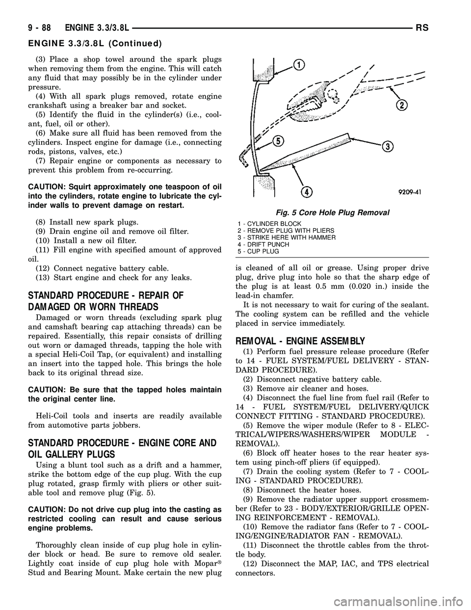
STANDARD PROCEDURE - ENGINE CORE AND
OIL GALLERY PLUGS
Using a blunt tool such as a drift and a hammer,
strike the bottom edge of the cup plug. With the cup
plug rotated, grasp firmly with pliers or other suit-
able tool and remove plug (Fig. 5).
CAUTION: Do not drive cup plug into the casting as
restricted cooling can result and cause serious
engine problems.
Thoroughly clean inside of cup plug hole in cylin-
der block or head. Be sure to remove old sealer.
Lightly coat inside of cup plug hole with Mopart
Stud and Bearing Mount. Make certain the new plugis cleaned of all oil or grease. Using proper drive
plug, drive plug into hole so that the sharp edge of
the plug is at least 0.5 mm (0.020 in.) inside the
lead-in chamfer.
It is not necessary to wait for curing of the sealant.
The cooling system can be refilled and the vehicle
placed in service immediately.
REMOVAL - ENGINE ASSEMBLY
(1) Perform fuel pressure release procedure (Refer
to 14 - FUEL SYSTEM/FUEL DELIVERY - STAN-
DARD PROCEDURE).
(2) Disconnect negative battery cable.
(3) Remove air cleaner and hoses.
(4) Disconnect the fuel line from fuel rail (Refer to
14 - FUEL SYSTEM/FUEL DELIVERY/QUICK
CONNECT FITTING - STANDARD PROCEDURE).
(5) Remove the wiper module (Refer to 8 - ELEC-
TRICAL/WIPERS/WASHERS/WIPER MODULE -
REMOVAL).
(6) Block off heater hoses to the rear heater sys-
tem using pinch-off pliers (if equipped).
(7) Drain the cooling system (Refer to 7 - COOL-
ING - STANDARD PROCEDURE).
(8) Disconnect the heater hoses.
(9) Remove the radiator upper support crossmem-
ber (Refer to 23 - BODY/EXTERIOR/GRILLE OPEN-
ING REINFORCEMENT - REMOVAL).
(10) Remove the radiator fans (Refer to 7 - COOL-
ING/ENGINE/RADIATOR FAN - REMOVAL).
(11) Disconnect the throttle cables from the throt-
tle body.
(12) Disconnect the MAP, IAC, and TPS electrical
connectors.
Fig. 5 Core Hole Plug Removal
1 - CYLINDER BLOCK
2 - REMOVE PLUG WITH PLIERS
3 - STRIKE HERE WITH HAMMER
4 - DRIFT PUNCH
5 - CUP PLUG
9 - 88 ENGINE 3.3/3.8LRS
ENGINE 3.3/3.8L (Continued)
Page 1281 of 2339
Remove all gasket material from cylinder head and
block (Refer to 9 - ENGINE - STANDARD PROCE-
DURE). Be careful not to gouge or scratch the alumi-
num head sealing surface.
Clean all engine oil passages.
INSPECTION
(1) Before cleaning, check for leaks, damage and
cracks.
(2) Clean cylinder head and oil passages.
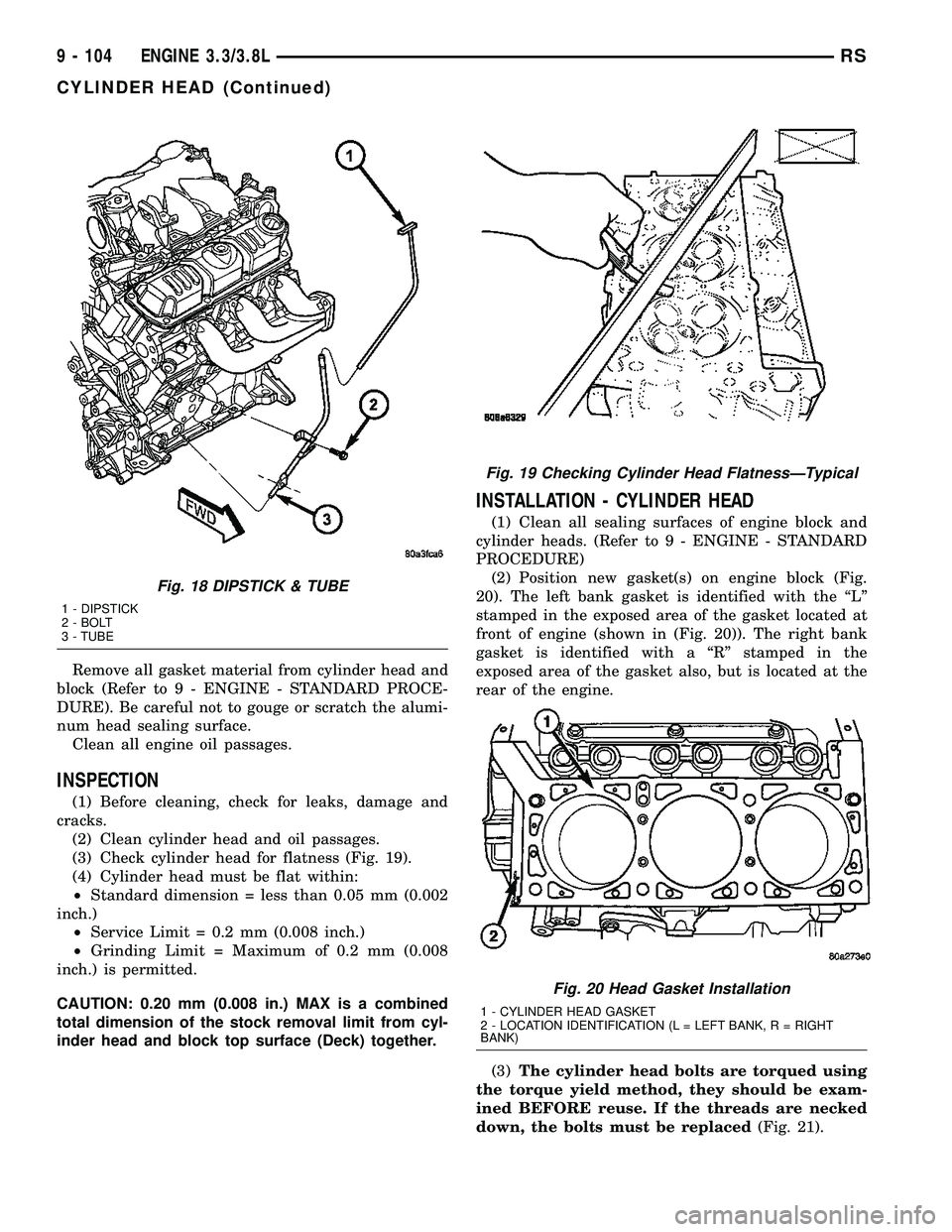
(3) Check cylinder head for flatness (Fig. 19).
(4) Cylinder head must be flat within:
²Standard dimension = less than 0.05 mm (0.002
inch.)
²Service Limit = 0.2 mm (0.008 inch.)
²Grinding Limit = Maximum of 0.2 mm (0.008
inch.) is permitted.
CAUTION: 0.20 mm (0.008 in.) MAX is a combined
total dimension of the stock removal limit from cyl-
inder head and block top surface (Deck) together.
INSTALLATION - CYLINDER HEAD
(1) Clean all sealing surfaces of engine block and
cylinder heads. (Refer to 9 - ENGINE - STANDARD
PROCEDURE)
(2) Position new gasket(s) on engine block (Fig.
20). The left bank gasket is identified with the ªLº
stamped in the exposed area of the gasket located at
front of engine (shown in (Fig. 20)). The right bank
gasket is identified with a ªRº stamped in the
exposed area of the gasket also, but is located at the
rear of the engine.
(3)The cylinder head bolts are torqued using
the torque yield method, they should be exam-
ined BEFORE reuse. If the threads are necked
down, the bolts must be replaced(Fig. 21).
Fig. 18 DIPSTICK & TUBE
1 - DIPSTICK
2 - BOLT
3 - TUBE
Fig. 19 Checking Cylinder Head FlatnessÐTypical
Fig. 20 Head Gasket Installation
1 - CYLINDER HEAD GASKET
2 - LOCATION IDENTIFICATION (L = LEFT BANK, R = RIGHT
BANK)
9 - 104 ENGINE 3.3/3.8LRS
CYLINDER HEAD (Continued)
Page 1282 of 2339
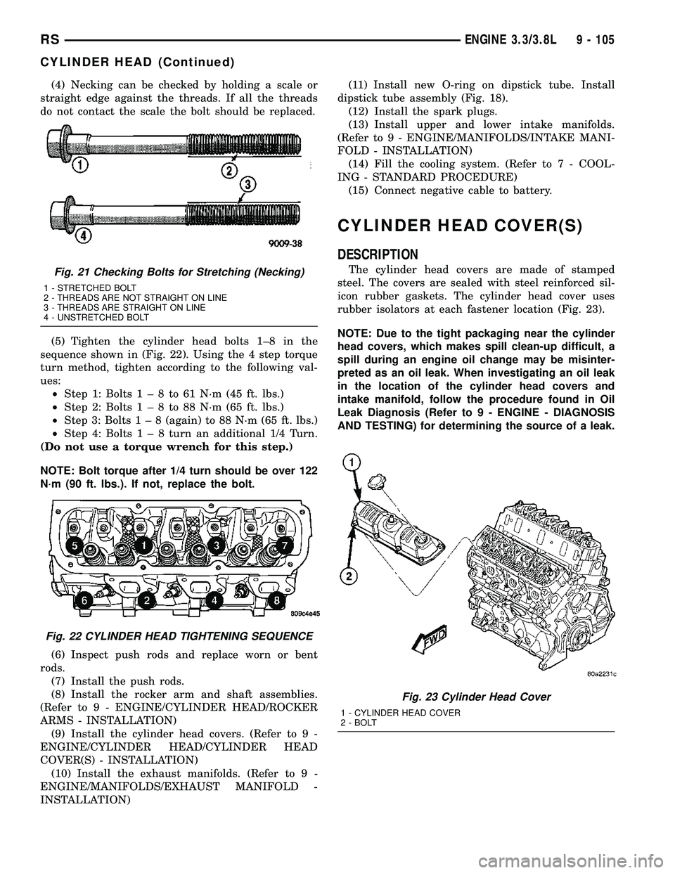
(4) Necking can be checked by holding a scale or
straight edge against the threads. If all the threads
do not contact the scale the bolt should be replaced.
(5) Tighten the cylinder head bolts 1±8 in the
sequence shown in (Fig. 22). Using the 4 step torque
turn method, tighten according to the following val-
ues:
²Step 1: Bolts1±8to61N´m(45ft.lbs.)
²Step 2: Bolts1±8to88N´m(65ft.lbs.)
²Step 3: Bolts1±8(again) to 88 N´m (65 ft. lbs.)
²Step 4: Bolts1±8turn an additional 1/4 Turn.
(Do not use a torque wrench for this step.)
NOTE: Bolt torque after 1/4 turn should be over 122
N´m (90 ft. lbs.). If not, replace the bolt.
(6) Inspect push rods and replace worn or bent
rods.
(7) Install the push rods.
(8) Install the rocker arm and shaft assemblies.
(Refer to 9 - ENGINE/CYLINDER HEAD/ROCKER
ARMS - INSTALLATION)
(9) Install the cylinder head covers. (Refer to 9 -
ENGINE/CYLINDER HEAD/CYLINDER HEAD
COVER(S) - INSTALLATION)
(10) Install the exhaust manifolds. (Refer to 9 -
ENGINE/MANIFOLDS/EXHAUST MANIFOLD -
INSTALLATION)(11) Install new O-ring on dipstick tube. Install
dipstick tube assembly (Fig. 18).
(12) Install the spark plugs.
(13) Install upper and lower intake manifolds.
(Refer to 9 - ENGINE/MANIFOLDS/INTAKE MANI-
FOLD - INSTALLATION)
(14) Fill the cooling system. (Refer to 7 - COOL-
ING - STANDARD PROCEDURE)
(15) Connect negative cable to battery.
CYLINDER HEAD COVER(S)
DESCRIPTION
The cylinder head covers are made of stamped
steel. The covers are sealed with steel reinforced sil-
icon rubber gaskets. The cylinder head cover uses
rubber isolators at each fastener location (Fig. 23).
NOTE: Due to the tight packaging near the cylinder
head covers, which makes spill clean-up difficult, a
spill during an engine oil change may be misinter-
preted as an oil leak. When investigating an oil leak
in the location of the cylinder head covers and
intake manifold, follow the procedure found in Oil
Leak Diagnosis (Refer to 9 - ENGINE - DIAGNOSIS
AND TESTING) for determining the source of a leak.Fig. 21 Checking Bolts for Stretching (Necking)
1 - STRETCHED BOLT
2 - THREADS ARE NOT STRAIGHT ON LINE
3 - THREADS ARE STRAIGHT ON LINE
4 - UNSTRETCHED BOLT
Fig. 22 CYLINDER HEAD TIGHTENING SEQUENCE
Fig. 23 Cylinder Head Cover
1 - CYLINDER HEAD COVER
2 - BOLT
RSENGINE 3.3/3.8L9 - 105
CYLINDER HEAD (Continued)
Page 1292 of 2339
REMOVAL
(1) Remove the valve springs. (Refer to 9 -
ENGINE/CYLINDER HEAD/VALVE SPRINGS -
REMOVAL)
(2) Remove the valve stem seal (Fig. 44).
INSTALLATION
(1) Install the valve stem seal squarely over the
valve guide, using the valve stem as a guide (Fig.
44). Do not force the seal against top of the valve
guide.
(2) Install the valve spring. (Refer to 9 - ENGINE/
CYLINDER HEAD/VALVE SPRINGS - INSTALLA-
TION)
ENGINE BLOCK
DESCRIPTION
The cylinder block is made of cast iron and is a
deep skirt design.
STANDARD PROCEDURE - CYLINDER BORE
HONING
(1) Used carefully, the cylinder bore resizing hone,
recommended tool C-823 or equivalent, equipped
with 220 grit stones, is the best tool for this honing
procedure. In addition to deglazing, it will reduce
taper and out-of-round as well as removing light
scuffing, scoring or scratches. Usually a few strokes
will clean up a bore and maintain the required lim-
its.
(2) Deglazing of the cylinder walls may be done
using a cylinder surfacing hone, recommended tool
C-3501 or equivalent, equipped with 280 grit stones,
if the cylinder bore is straight and round. 20±60
strokes depending on the bore condition, will be suf-
ficient to provide a satisfactory surface. Use a light
honing oil.Do not use engine or transmission oil,
mineral spirits or kerosene.Inspect cylinder walls
after each 20 strokes.
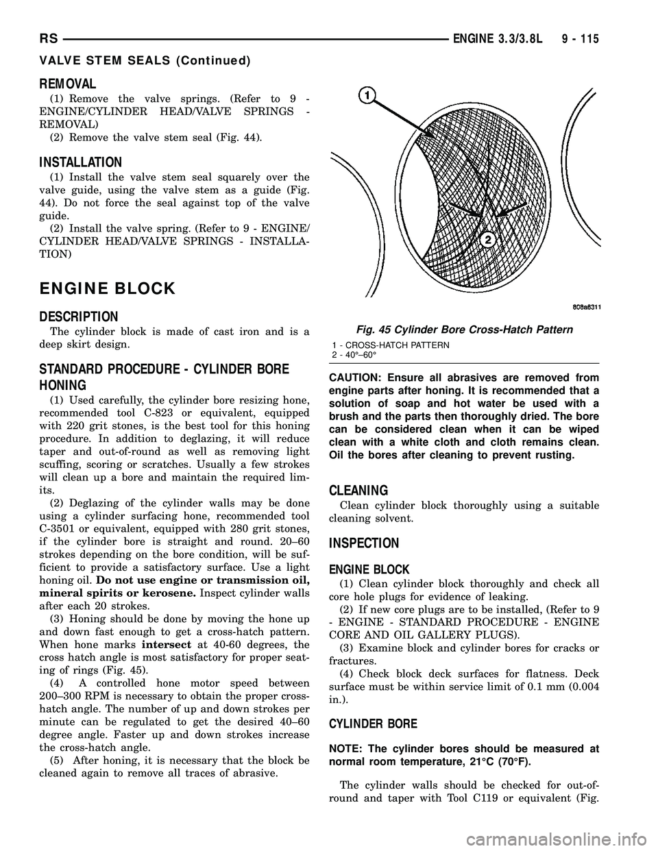
(3) Honing should be done by moving the hone up
and down fast enough to get a cross-hatch pattern.
When hone marksintersectat 40-60 degrees, the
cross hatch angle is most satisfactory for proper seat-
ing of rings (Fig. 45).
(4) A controlled hone motor speed between
200±300 RPM is necessary to obtain the proper cross-
hatch angle. The number of up and down strokes per
minute can be regulated to get the desired 40±60
degree angle. Faster up and down strokes increase
the cross-hatch angle.
(5) After honing, it is necessary that the block be
cleaned again to remove all traces of abrasive.CAUTION: Ensure all abrasives are removed from
engine parts after honing. It is recommended that a
solution of soap and hot water be used with a
brush and the parts then thoroughly dried. The bore
can be considered clean when it can be wiped
clean with a white cloth and cloth remains clean.
Oil the bores after cleaning to prevent rusting.
CLEANING
Clean cylinder block thoroughly using a suitable
cleaning solvent.
INSPECTION
ENGINE BLOCK
(1) Clean cylinder block thoroughly and check all
core hole plugs for evidence of leaking.
(2) If new core plugs are to be installed, (Refer to 9
- ENGINE - STANDARD PROCEDURE - ENGINE
CORE AND OIL GALLERY PLUGS).
(3) Examine block and cylinder bores for cracks or
fractures.
(4) Check block deck surfaces for flatness. Deck
surface must be within service limit of 0.1 mm (0.004
in.).
CYLINDER BORE
NOTE: The cylinder bores should be measured at
normal room temperature, 21ÉC (70ÉF).
The cylinder walls should be checked for out-of-
round and taper with Tool C119 or equivalent (Fig.
Fig. 45 Cylinder Bore Cross-Hatch Pattern
1 - CROSS-HATCH PATTERN
2 - 40ɱ60É
RSENGINE 3.3/3.8L9 - 115
VALVE STEM SEALS (Continued)