2005 CHRYSLER CARAVAN check oil
[x] Cancel search: check oilPage 340 of 2339

RELAY CIRCUIT TEST
(1) The relay common feed terminal cavity (30) is
connected to battery voltage and should be hot at all
times. If OK, go to Step 2. If not OK, repair the open
circuit to the PDC fuse as required.
(2) The relay normally closed terminal (87A) is
connected to terminal 30 in the de-energized position,
but is not used for this application. Go to Step 3.
(3) The relay normally open terminal (87) is con-
nected to the common feed terminal (30) in the ener-
gized position. This terminal supplies battery voltage
to the starter solenoid field coils. There should be
continuity between the cavity for relay terminal 87
and the starter solenoid terminal at all times. If OK,
go to Step 4. If not OK, repair the open circuit to the
starter solenoid as required.
(4) The coil battery terminal (85) is connected to
the electromagnet in the relay. It is energized when
the ignition switch is held in the Start position and
the clutch pedal is depressed (manual trans). Check
for battery voltage at the cavity for relay terminal 86
with the ignition switch in the Start position and the
clutch pedal is depressed (manual trans), and no
voltage when the ignition switch is released to the
On position. If OK, go to Step 5. If not OK, check for
an open or short circuit to the ignition switch and
repair, if required. If the circuit to the ignition switch
is OK, see the Ignition Switch Test procedure in this
group.
(5) The coil ground terminal (86) is connected to
the electromagnet in the relay. It is grounded by the
PCM if the conditions are right to start the car. For
automatic trans. cars the PCM must see Park Neu-
tral switch low and near zero engine speed (rpm).
For manual trans. cars the PCM only needs to see
near zero engine speed (rpm) and low clutch inter-
lock input and see near zero engine speed (rpm). To
diagnose the Park Neutral switch of the trans range
sensor refer to the transaxle section. Check for conti-
nuity to ground while the ignition switch is in the
start position and if equipped the clutch pedal
depressed. If not OK and the vehicle has an auto-
matic trans. verify Park Neutral switch operation. If
that checks OK check for continuity between PCM
and the terminal 86. Repair open circuit as required.
Also check the clutch interlock switch operation if
equipped with a manual transmission. If OK, the
PCM may be defective.
SAFETY SWITCHES
For diagnostics of the Transmission Range Sensor,
refer to the Transaxle section for more information.
If equipped with Clutch Interlock/Upstop Switch,
refer to Diagnosis and Testing in the Clutch section.
IGNITION SWITCH
After testing starter solenoid and relay, test igni-
tion switch and wiring. Refer to the Ignition Section
or Wiring Diagrams for more information. Check all
wiring for opens or shorts, and all connectors for
being loose or corroded.
BATTERY
For battery diagnosis and testing, refer to the Bat-
tery section for procedures.
ALL RELATED WIRING AND CONNECTORS
Refer to Wiring Diagrams for more information.
DIAGNOSIS AND TESTING - FEED CIRCUIT
RESISTANCE TEST
Before proceeding with this operation, review Diag-
nostic Preparation and Starter Feed Circuit Tests.
The following operation will require a voltmeter,
accurate to 1/10 of a volt.
CAUTION: Ignition and Fuel systems must be dis-
abled to prevent engine start while performing the
following tests.
(1) To disable the Ignition and Fuel systems, dis-
connect the Automatic Shutdown Relay (ASD). The
ASD relay is located in the Power Distribution Cen-
ter (PDC). Refer to the PDC cover for proper relay
location.
(2) Gain access to battery terminals.
(3) With all wiring harnesses and components
properly connected, perform the following:
(a) Connect the negative lead of the voltmeter to
the battery negative post, and positive lead to the
battery negative cable clamp. Rotate and hold the
ignition switch in the START position. Observe the
voltmeter. If voltage is detected, correct poor con-
tact between cable clamp and post.
(b) Connect positive lead of the voltmeter to the
battery positive post, and negative lead to the bat-
tery positive cable clamp. Rotate and hold the igni-
tion switch key in the START position. Observe the
voltmeter. If voltage is detected, correct poor con-
tact between the cable clamp and post.
(c) Connect negative lead of voltmeter to battery
negative terminal, and positive lead to engine
block near the battery cable attaching point.
Rotate and hold the ignition switch in the START
position. If voltage reads above 0.2 volt, correct
poor contact at ground cable attaching point. If
voltage reading is still above 0.2 volt after correct-
ing poor contacts, replace ground cable.
(4) Connect positive voltmeter lead to the starter
motor housing and the negative lead to the battery
negative terminal. Hold the ignition switch key in
RSSTARTING8F-35
STARTING (Continued)
Page 366 of 2339

FIRING ORDERAUTO SHUT DOWN RELAY
DESCRIPTION
The relay is located in the Power Distribution Cen-
ter (PDC). For the location of the relay within the
PDC, refer to the PDC cover for location. Check elec-
trical terminals for corrosion and repair as necessary
OPERATION
The engine switched battery (NGC vehicles)
informs the PCM when the ASD relay energizes. A 12
volt signal at this input indicates to the PCM that
the ASD has been activated. This input is also used
to power certain drivers on NGC vehicles.
When energized, the ASD relay on NGC vehicles
provides power to operate the injectors, ignition coil,
generator field, O2 sensor heaters (both upstream
and downstream), evaporative purge solenoid, EGR
solenoid (if equipped) wastegate solenoid (if
equipped), and NVLD solenoid (if equipped).
The ASD relay also provides a sense circuit to the
PCM for diagnostic purposes. If the PCM does not
receive 12 volts from this input after grounding the
control side of the ASD relay, it sets a Diagnostic
Trouble Code (DTC). The PCM energizes the ASD
any time there is an engine speed that exceeds a pre-
determined value (typically about 50 rpm). The ASD
relay can also be energized after the engine has been
turned off to perform an O2 sensor heater test, if
vehicle is equipped with OBD II diagnostics.
As mentioned earlier, the PCM energizes the ASD
relay during an O2 sensor heater test. On NGC vehi-
cles it checks the O2 heater upon vehicle start. The
PCM still operates internally to perform several
checks, including monitoring the O2 sensor heaters.
FIRING ORDER 2.4L
Firing Order 1-2-3-4-5-6 3.3/3.8L
1 - Electrical Connector
RSIGNITION CONTROL8I-3
IGNITION CONTROL (Continued)
Page 373 of 2339

REMOVAL
When replacing the spark plugs and spark plug
cables, route the cables correctly and secure them in
the appropriate retainers. Failure to route the cables
properly can cause the radio to reproduce ignition
noise, cross ignition of the spark plugs orshort cir-
cuit the cables to ground.
Always remove cables by grasping at the boot,
rotating the boot 1/2 turn, and pulling straight back
in a steady motion.
(1) Prior to removing the spark plug, spray com-
pressed air around the spark plug hole and the area
around the spark plug.
(2) Remove the spark plug using a quality socket
with a foam insert.
(3) Inspect the spark plug condition.
INSTALLATION
When replacing the spark plugs and spark plug
cables, route the cables correctly and secure them in
the appropriate retainers. Failure to route the cables
properly can cause the radio to reproduce ignition
noise, cross ignition of the spark plugs orshort cir-
cuit the cables to ground.
(1) Coat threads of spark plug with anti-seize. Be
sure not to get anti-seizeANYWHERE BUT ON
THE THREADS OF THE SPARK PLUG as
shown in (Fig. 13).
(2) To avoid cross threading, start the spark plug
into the cylinder head by hand.
(3) Tighten spark plugs to 17.5 N´m (13 ft. lbs.)
torque.
(4) Install spark plug cables over spark plugs. A
click will be heard and felt when the cable properly
attaches to the spark plug.
SPARK PLUG CABLE
DESCRIPTION
Spark Plug cables are sometimes referred to as
secondary ignition wires. The wires transfer electri-
cal current from the ignition coil pack to individualspark plugs at each cylinder. The resistive spark plug
cables are of nonmetallic construction. The cables
provide suppression of radio frequency emissions
from the ignition system.
Check the spark plug cable connections for good
contact at the coil, and spark plugs. Terminals should
be fully seated. The insulators should be in good con-
dition and should fit tightly on the coil, and spark
plugs. Spark plug cables with insulators that are
cracked or torn must be replaced.
Clean Spark Plug cables with a cloth moistened
with a non-flammable solvent. Wipe the cables dry.
Check for brittle or cracked insulation. The spark
plug cables and spark plug boots are made from high
temperature materials.
REMOVAL - 2.0/2.4L
Failure to route the cables properly could cause the
radio to reproduce ignition noise, cross ignition of the
spark plugs or short circuit the cables to ground.
Remove spark plug cable from coil first.
Always remove the spark plug cable by grasping
the top of the spark plug insulator, turning the boot
1/2 turn and pulling straight up in a steady motion.
INSTALLATION - 2.0/2.4L
Failure to route the cables properly could cause the
radio to reproduce ignition noise, cross ignition of the
spark plugs or short circuit the cables to ground.
Install spark plug insulators over spark plugs.
Ensure the top of the spark plug insulator covers the
upper end of the spark plug tube, then connect the
other end to coil pack.
8I - 10 IGNITION CONTROLRS
SPARK PLUG (Continued)
Page 374 of 2339

INSTRUMENT CLUSTER
TABLE OF CONTENTS
page page
INSTRUMENT CLUSTER
DESCRIPTION..........................1
OPERATION............................1
DIAGNOSIS AND TESTING
DIAGNOSIS AND TESTING - SELF-
DIAGNOSTICS.........................2
DIAGNOSIS AND TESTING - CLUSTER
DIAGNOSIS...........................3REMOVAL.............................11
INSTALLATION.........................11
CLUSTER LENS
REMOVAL.............................11
INSTALLATION.........................11
INSTRUMENT CLUSTER
DESCRIPTION
The instrumentation gauges are contained in a
subdial assembly within the instrument cluster. The
individual gauges are not serviceable. If one of the
cluster gauges becomes faulty, the entire cluster
would require replacement.
The Mechanical Instrument Cluster (MIC) with a
tachometer is equipped with a electronic vacuum flu-
orescent transmission range indicator (PRND3L),
odometer, and trip odometer display.
The MIC without a tachometer is equipped with a
Light Emitting Diode (LED) transmission range indi-
cator (PRND3L) and a vacuum fluorescent odometer
display.
The MIC is equipped with the following warning
lamps.
²Lift Gate Ajar
²Low Fuel Level
²Low Windshield Washer Fluid Level
²Cruise
²Battery Voltage
²Fasten Seat Belt
²Door Ajar
²Coolant Temperature
²Anti-Lock Brake
²Brake
²Oil Pressure
²MIL (Malfunction Indicator Lamp)
²VTSS/SKIS Indicator
²Airbag
²Traction Control
²Autostick
Export Only- uses a message center that displays
the following telltales:
²Turns Signals
²High Beam
²Tire Pressure Monitoring (TPM)²Glow Plug (Export Only)
²Supplemental Cabin Heater (Export Only)WATER IN FUEL LAMP - EXPORT
The Water In Fuel Lamp is located in the message
center. When moisture is found within the fuel sys-
tem, the sensor sends a message via the PCI data
bus to the instrument cluster. The MIC illuminates
the bulb in the message center, The sensor is located
underneath the vehicle, directly above the rear axle.
The sensor is housed within the fuel filter/water sep-
arator assembly cover. The sensor is not serviced sep-
arately. If found defective, the entire assembly cover
must be replaced.
OPERATION
Refer to the vehicle Owner's Manual for operation
instructions and conditions for the Instrument Clus-
ter Gauges.
WATER IN FUEL LAMP/SENSOR - EXPORT
The Water In Fuel Sensor is a resistive type
switch. It is calibrated to sense the different resis-
tance between diesel fuel and water. When water
enters the fuel system, it is caught in the bottom of
the fuel filter/water separator assembly, where the
sensor is located. Water has less resistance than die-
sel fuel. The sensor then sends a PCI data bus mes-
sage to the instrument cluster to illuminate the
lamp.
If the lamp is inoperative, perform the self diag-
nostic test on the instrument cluster to check the
lamp operation before continuing diagnosis.
RSINSTRUMENT CLUSTER8J-1
Page 1179 of 2339

INSTALLATION
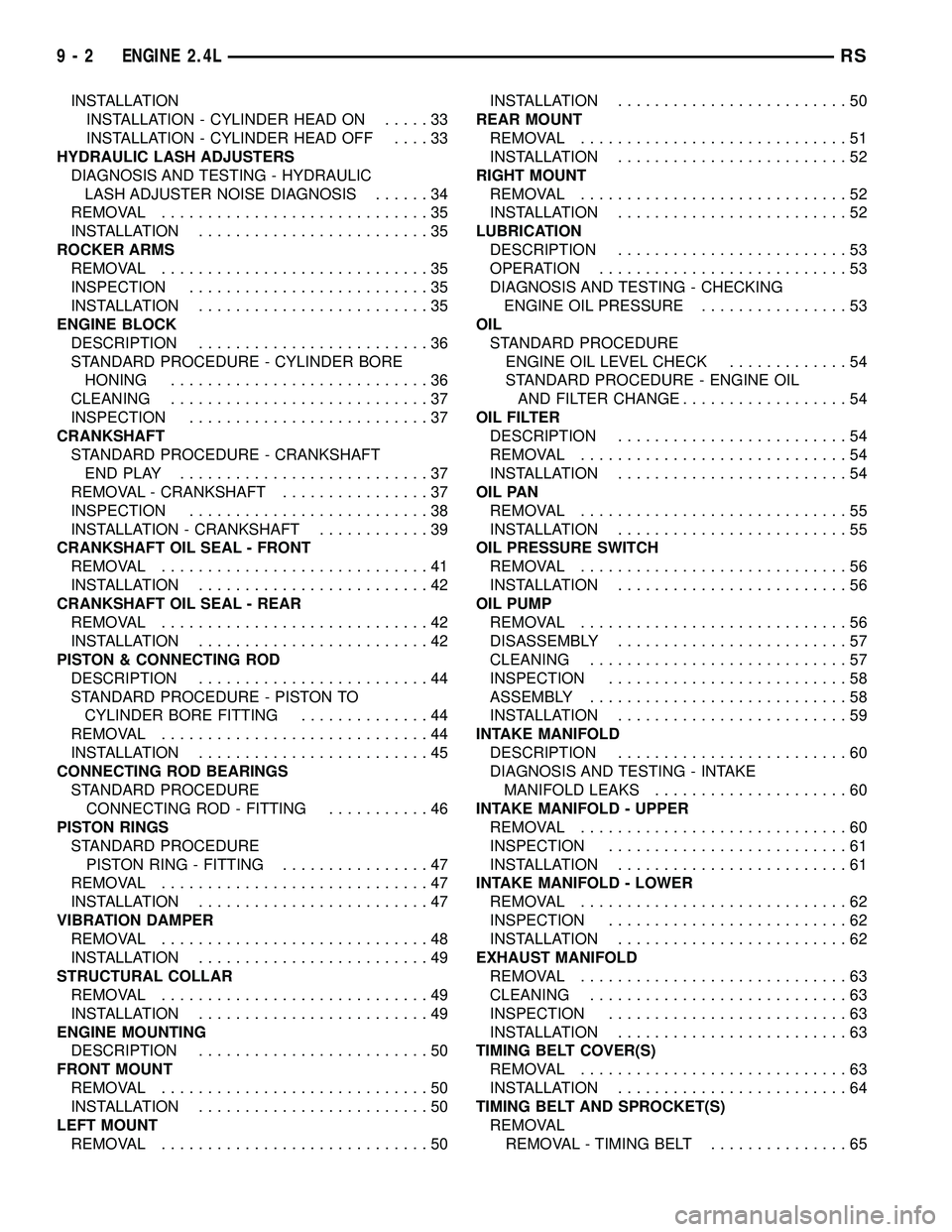
INSTALLATION - CYLINDER HEAD ON.....33
INSTALLATION - CYLINDER HEAD OFF....33
HYDRAULIC LASH ADJUSTERS
DIAGNOSIS AND TESTING - HYDRAULIC
LASH ADJUSTER NOISE DIAGNOSIS......34
REMOVAL.............................35
INSTALLATION.........................35
ROCKER ARMS
REMOVAL.............................35
INSPECTION..........................35
INSTALLATION.........................35
ENGINE BLOCK
DESCRIPTION.........................36
STANDARD PROCEDURE - CYLINDER BORE
HONING............................36
CLEANING............................37
INSPECTION..........................37
CRANKSHAFT
STANDARD PROCEDURE - CRANKSHAFT
ENDPLAY ...........................37
REMOVAL - CRANKSHAFT................37
INSPECTION..........................38
INSTALLATION - CRANKSHAFT............39
CRANKSHAFT OIL SEAL - FRONT
REMOVAL.............................41
INSTALLATION.........................42
CRANKSHAFT OIL SEAL - REAR
REMOVAL.............................42
INSTALLATION.........................42
PISTON & CONNECTING ROD
DESCRIPTION.........................44
STANDARD PROCEDURE - PISTON TO
CYLINDER BORE FITTING..............44
REMOVAL.............................44
INSTALLATION.........................45
CONNECTING ROD BEARINGS
STANDARD PROCEDURE
CONNECTING ROD - FITTING...........46
PISTON RINGS
STANDARD PROCEDURE
PISTON RING - FITTING................47
REMOVAL.............................47
INSTALLATION.........................47
VIBRATION DAMPER
REMOVAL.............................48
INSTALLATION.........................49
STRUCTURAL COLLAR
REMOVAL.............................49
INSTALLATION.........................49
ENGINE MOUNTING
DESCRIPTION.........................50
FRONT MOUNT
REMOVAL.............................50
INSTALLATION.........................50
LEFT MOUNT
REMOVAL.............................50INSTALLATION.........................50
REAR MOUNT
REMOVAL.............................51
INSTALLATION.........................52
RIGHT MOUNT
REMOVAL.............................52
INSTALLATION.........................52
LUBRICATION
DESCRIPTION.........................53
OPERATION...........................53
DIAGNOSIS AND TESTING - CHECKING
ENGINE OIL PRESSURE................53
OIL
STANDARD PROCEDURE
ENGINE OIL LEVEL CHECK.............54
STANDARD PROCEDURE - ENGINE OIL
AND FILTER CHANGE..................54
OIL FILTER
DESCRIPTION.........................54
REMOVAL.............................54
INSTALLATION.........................54
OIL PAN
REMOVAL.............................55
INSTALLATION.........................55
OIL PRESSURE SWITCH
REMOVAL.............................56
INSTALLATION.........................56
OIL PUMP
REMOVAL.............................56
DISASSEMBLY.........................57
CLEANING............................57
INSPECTION..........................58
ASSEMBLY............................58
INSTALLATION.........................59
INTAKE MANIFOLD
DESCRIPTION.........................60
DIAGNOSIS AND TESTING - INTAKE
MANIFOLD LEAKS.....................60
INTAKE MANIFOLD - UPPER
REMOVAL.............................60
INSPECTION..........................61
INSTALLATION.........................61
INTAKE MANIFOLD - LOWER
REMOVAL.............................62
INSPECTION..........................62
INSTALLATION.........................62
EXHAUST MANIFOLD
REMOVAL.............................63
CLEANING............................63
INSPECTION..........................63
INSTALLATION.........................63
TIMING BELT COVER(S)
REMOVAL.............................63
INSTALLATION.........................64
TIMING BELT AND SPROCKET(S)
REMOVAL
REMOVAL - TIMING BELT...............65
9 - 2 ENGINE 2.4LRS
Page 1181 of 2339

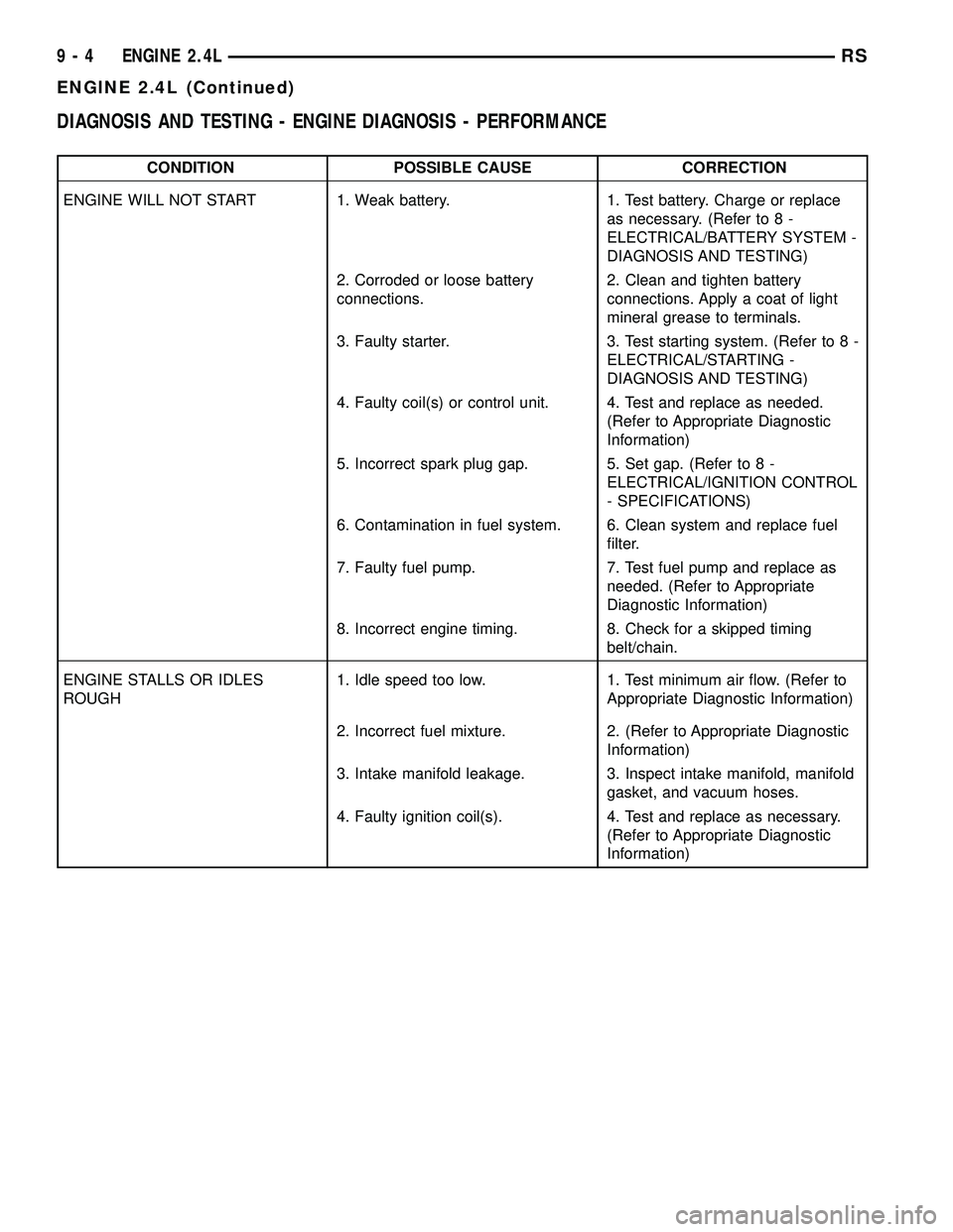
DIAGNOSIS AND TESTING - ENGINE DIAGNOSIS - PERFORMANCE
CONDITION POSSIBLE CAUSE CORRECTION
ENGINE WILL NOT START 1. Weak battery. 1. Test battery. Charge or replace
as necessary. (Refer to 8 -
ELECTRICAL/BATTERY SYSTEM -
DIAGNOSIS AND TESTING)
2. Corroded or loose battery
connections.2. Clean and tighten battery
connections. Apply a coat of light
mineral grease to terminals.
3. Faulty starter. 3. Test starting system. (Refer to 8 -
ELECTRICAL/STARTING -
DIAGNOSIS AND TESTING)
4. Faulty coil(s) or control unit. 4. Test and replace as needed.
(Refer to Appropriate Diagnostic
Information)
5. Incorrect spark plug gap. 5. Set gap. (Refer to 8 -
ELECTRICAL/IGNITION CONTROL
- SPECIFICATIONS)
6. Contamination in fuel system. 6. Clean system and replace fuel
filter.
7. Faulty fuel pump. 7. Test fuel pump and replace as
needed. (Refer to Appropriate
Diagnostic Information)
8. Incorrect engine timing. 8. Check for a skipped timing
belt/chain.
ENGINE STALLS OR IDLES
ROUGH1. Idle speed too low. 1. Test minimum air flow. (Refer to
Appropriate Diagnostic Information)
2. Incorrect fuel mixture. 2. (Refer to Appropriate Diagnostic
Information)
3. Intake manifold leakage. 3. Inspect intake manifold, manifold
gasket, and vacuum hoses.
4. Faulty ignition coil(s). 4. Test and replace as necessary.
(Refer to Appropriate Diagnostic
Information)
9 - 4 ENGINE 2.4LRS
ENGINE 2.4L (Continued)
Page 1183 of 2339

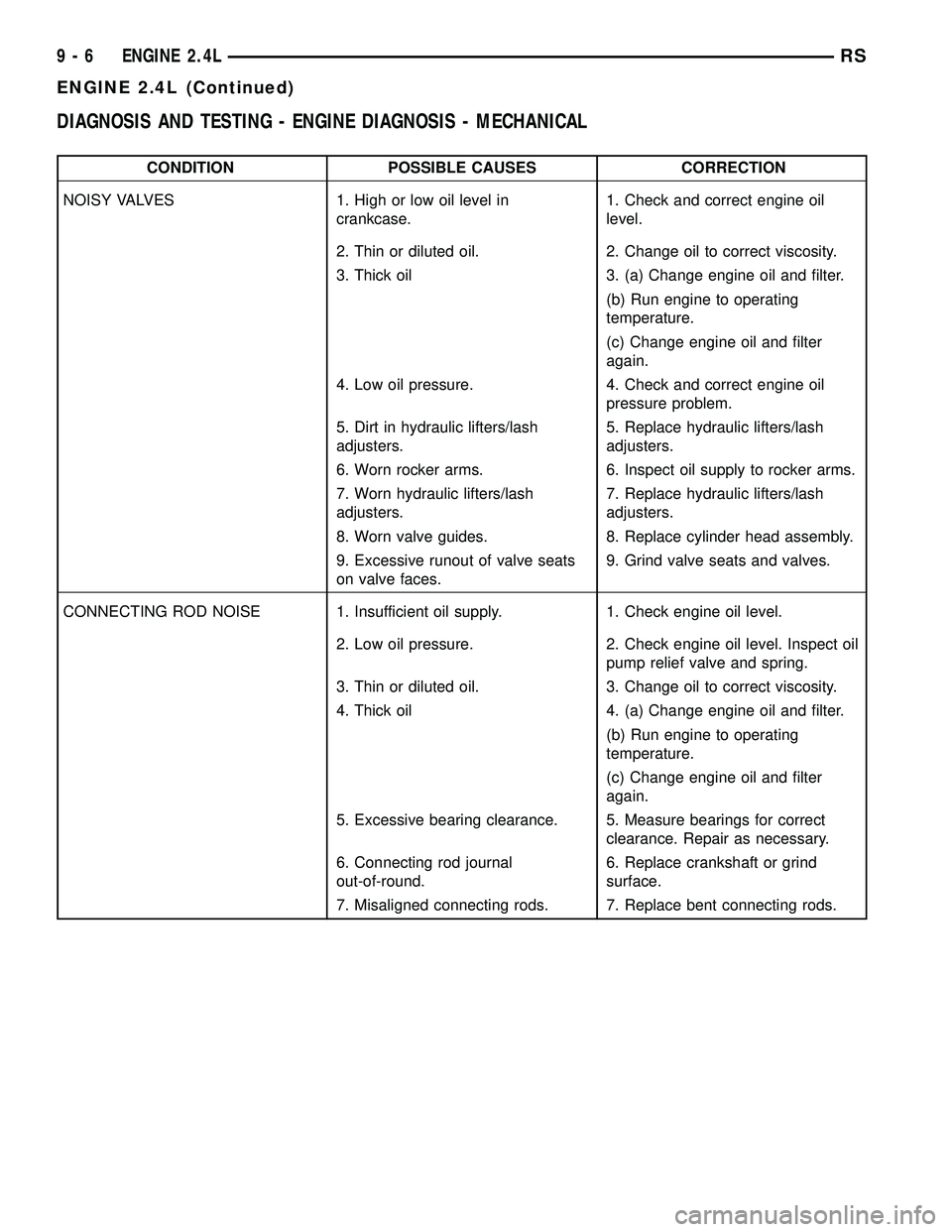
DIAGNOSIS AND TESTING - ENGINE DIAGNOSIS - MECHANICAL
CONDITION POSSIBLE CAUSES CORRECTION
NOISY VALVES 1. High or low oil level in
crankcase.1. Check and correct engine oil
level.
2. Thin or diluted oil. 2. Change oil to correct viscosity.
3. Thick oil 3. (a) Change engine oil and filter.
(b) Run engine to operating
temperature.
(c) Change engine oil and filter
again.
4. Low oil pressure. 4. Check and correct engine oil
pressure problem.
5. Dirt in hydraulic lifters/lash
adjusters.5. Replace hydraulic lifters/lash
adjusters.
6. Worn rocker arms. 6. Inspect oil supply to rocker arms.
7. Worn hydraulic lifters/lash
adjusters.7. Replace hydraulic lifters/lash
adjusters.
8. Worn valve guides. 8. Replace cylinder head assembly.
9. Excessive runout of valve seats
on valve faces.9. Grind valve seats and valves.
CONNECTING ROD NOISE 1. Insufficient oil supply. 1. Check engine oil level.
2. Low oil pressure. 2. Check engine oil level. Inspect oil
pump relief valve and spring.
3. Thin or diluted oil. 3. Change oil to correct viscosity.
4. Thick oil 4. (a) Change engine oil and filter.
(b) Run engine to operating
temperature.
(c) Change engine oil and filter
again.
5. Excessive bearing clearance. 5. Measure bearings for correct
clearance. Repair as necessary.
6. Connecting rod journal
out-of-round.6. Replace crankshaft or grind
surface.
7. Misaligned connecting rods. 7. Replace bent connecting rods.
9 - 6 ENGINE 2.4LRS
ENGINE 2.4L (Continued)
Page 1184 of 2339

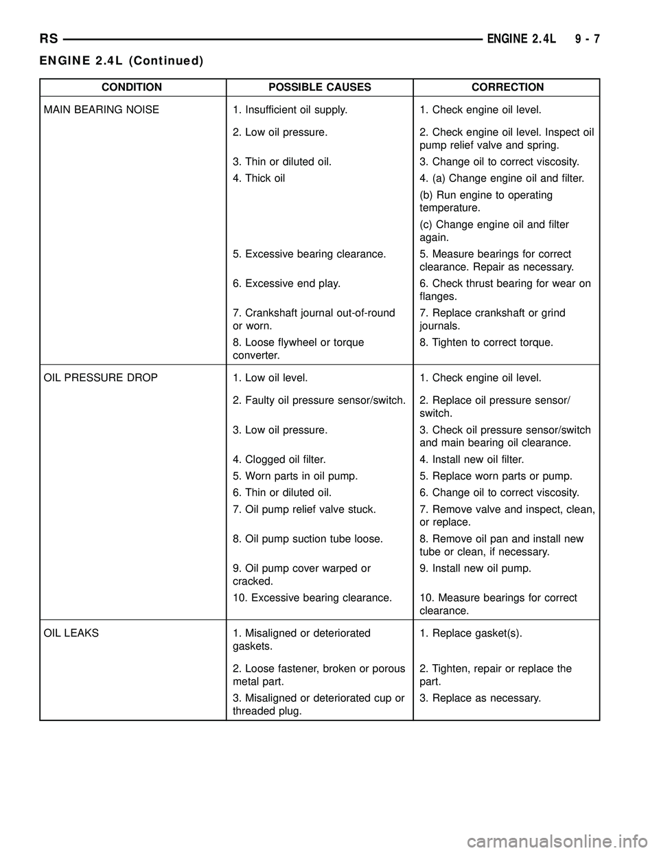
CONDITION POSSIBLE CAUSES CORRECTION
MAIN BEARING NOISE 1. Insufficient oil supply. 1. Check engine oil level.
2. Low oil pressure. 2. Check engine oil level. Inspect oil
pump relief valve and spring.
3. Thin or diluted oil. 3. Change oil to correct viscosity.
4. Thick oil 4. (a) Change engine oil and filter.
(b) Run engine to operating
temperature.
(c) Change engine oil and filter
again.
5. Excessive bearing clearance. 5. Measure bearings for correct
clearance. Repair as necessary.
6. Excessive end play. 6. Check thrust bearing for wear on
flanges.
7. Crankshaft journal out-of-round
or worn.7. Replace crankshaft or grind
journals.
8. Loose flywheel or torque
converter.8. Tighten to correct torque.
OIL PRESSURE DROP 1. Low oil level. 1. Check engine oil level.
2. Faulty oil pressure sensor/switch. 2. Replace oil pressure sensor/
switch.
3. Low oil pressure. 3. Check oil pressure sensor/switch
and main bearing oil clearance.
4. Clogged oil filter. 4. Install new oil filter.
5. Worn parts in oil pump. 5. Replace worn parts or pump.
6. Thin or diluted oil. 6. Change oil to correct viscosity.
7. Oil pump relief valve stuck. 7. Remove valve and inspect, clean,
or replace.
8. Oil pump suction tube loose. 8. Remove oil pan and install new
tube or clean, if necessary.
9. Oil pump cover warped or
cracked.9. Install new oil pump.
10. Excessive bearing clearance. 10. Measure bearings for correct
clearance.
OIL LEAKS 1. Misaligned or deteriorated
gaskets.1. Replace gasket(s).
2. Loose fastener, broken or porous
metal part.2. Tighten, repair or replace the
part.
3. Misaligned or deteriorated cup or
threaded plug.3. Replace as necessary.
RSENGINE 2.4L9-7
ENGINE 2.4L (Continued)