2005 CHRYSLER CARAVAN weight
[x] Cancel search: weightPage 1380 of 2339
(9)The fuel pump module electrical connec-
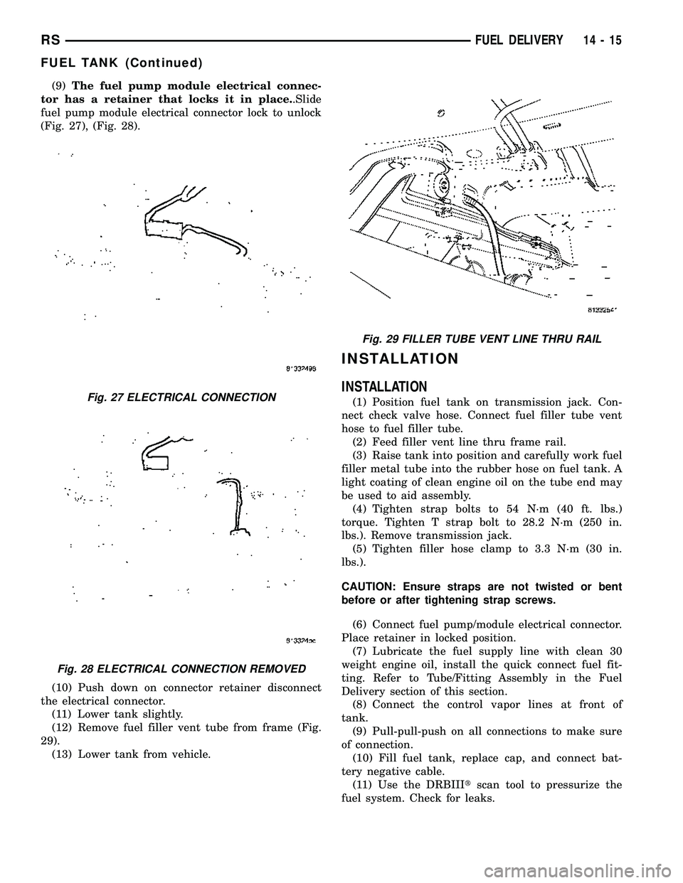
tor has a retainer that locks it in place..Slide
fuel pump module electrical connector lock to unlock
(Fig. 27), (Fig. 28).
(10) Push down on connector retainer disconnect
the electrical connector.
(11) Lower tank slightly.
(12) Remove fuel filler vent tube from frame (Fig.
29).
(13) Lower tank from vehicle.
INSTALLATION
INSTALLATION
(1) Position fuel tank on transmission jack. Con-
nect check valve hose. Connect fuel filler tube vent
hose to fuel filler tube.
(2) Feed filler vent line thru frame rail.
(3) Raise tank into position and carefully work fuel
filler metal tube into the rubber hose on fuel tank. A
light coating of clean engine oil on the tube end may
be used to aid assembly.
(4) Tighten strap bolts to 54 N´m (40 ft. lbs.)
torque. Tighten T strap bolt to 28.2 N´m (250 in.
lbs.). Remove transmission jack.
(5) Tighten filler hose clamp to 3.3 N´m (30 in.
lbs.).
CAUTION: Ensure straps are not twisted or bent
before or after tightening strap screws.
(6) Connect fuel pump/module electrical connector.
Place retainer in locked position.
(7) Lubricate the fuel supply line with clean 30
weight engine oil, install the quick connect fuel fit-
ting. Refer to Tube/Fitting Assembly in the Fuel
Delivery section of this section.
(8) Connect the control vapor lines at front of
tank.
(9) Pull-pull-push on all connections to make sure
of connection.
(10) Fill fuel tank, replace cap, and connect bat-
tery negative cable.
(11) Use the DRBIIItscan tool to pressurize the
fuel system. Check for leaks.Fig. 27 ELECTRICAL CONNECTION
Fig. 28 ELECTRICAL CONNECTION REMOVED
Fig. 29 FILLER TUBE VENT LINE THRU RAIL
RSFUEL DELIVERY14-15
FUEL TANK (Continued)
Page 1758 of 2339
TIRES/WHEELS
TABLE OF CONTENTS
page page
TIRES/WHEELS
DIAGNOSIS AND TESTING - TIRE AND
WHEEL VIBRATION.....................1
STANDARD PROCEDURE
STANDARD PROCEDURE - TIRE AND
WHEEL BALANCE......................5
STANDARD PROCEDURE - TIRE AND
WHEEL MATCH MOUNTING..............7
STANDARD PROCEDURE - TIRE AND
WHEEL ROTATION.....................7
REMOVAL
REMOVAL - TIRE AND WHEEL ASSEMBLY
(ALUMINUM WHEEL)....................8
REMOVAL - TIRE AND WHEEL ASSEMBLY
(STEEL WHEEL).......................8
INSTALLATION
INSTALLATION - TIRE AND WHEEL
ASSEMBLY (ALUMINUM WHEEL)..........8
INSTALLATION - TIRE AND WHEEL
ASSEMBLY (STEEL WHEEL)..............8
TIRE PRESSURE MONITORING
DESCRIPTION..........................9
OPERATION...........................10
SENSOR - TPM
DESCRIPTION.........................10
OPERATION...........................10
CAUTION.............................11
DIAGNOSIS AND TESTING - TIRE PRESSURE
SENSOR............................11
REMOVAL.............................11
INSTALLATION.........................11
TIRES
DESCRIPTION
DESCRIPTION - TIRE..................13
DESCRIPTION - RADIAL-PLY TIRES.......13
DESCRIPTION - REPLACEMENT TIRES....14
DESCRIPTION - SPARE TIRE
(TEMPORARY).......................14DIAGNOSIS AND TESTING
DIAGNOSIS AND TESTING - TIRE NOISE . . . 14
DIAGNOSIS AND TESTING - TIRE/VEHICLE
LEAD...............................14
DIAGNOSIS AND TESTING - TIRE WEAR
PATTERNS..........................16
DIAGNOSIS AND TESTING - TREAD WEAR
INDICATORS.........................16
STANDARD PROCEDURE
STANDARD PROCEDURE - TIRE INFLATION
PRESSURES.........................16
STANDARD PROCEDURE - TIRE
PRESSURE FOR HIGH SPEED
OPERATION.........................17
STANDARD PROCEDURE - TIRE LEAK
REPAIRING..........................17
CLEANING - TIRES.....................18
WHEELS
DESCRIPTION - WHEEL..................18
DIAGNOSIS AND TESTING - WHEEL
INSPECTION.........................19
CLEANING
WHEEL AND WHEEL TRIM CARE.........19
SPECIFICATIONS
WHEEL.............................19
WHEEL COVER
DESCRIPTION.........................19
REMOVAL.............................19
INSTALLATION.........................20
WHEEL MOUNTING STUDS - FRONT
REMOVAL.............................21
INSTALLATION.........................21
WHEEL MOUNTING STUDS - REAR
REMOVAL.............................22
INSTALLATION.........................22
TIRES/WHEELS
DIAGNOSIS AND TESTING - TIRE AND WHEEL
VIBRATION
Tire and wheel imbalance, runout and force varia-
tion can cause vehicles to exhibit steering wheel
vibration.
VISUAL INSPECTION
Visual inspection of the vehicle is recommended
prior to road testing or performing any other proce-
dure. Raise vehicle on a suitable hoist. (Refer to
LUBRICATION & MAINTENANCE/HOISTING -
STANDARD PROCEDURE)
Inspect for the following:
²Verify correct (OEM) wheel and tire, as well as
correct wheel weights. Aluminum wheels require
RSTIRES/WHEELS22-1
Page 1759 of 2339
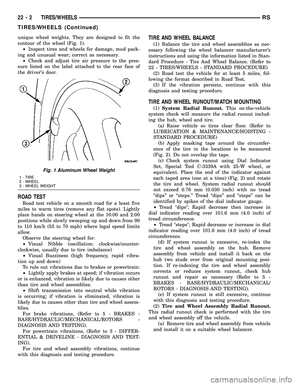
unique wheel weights. They are designed to fit the
contour of the wheel (Fig. 1).
²Inspect tires and wheels for damage, mud pack-
ing and unusual wear; correct as necessary.
²Check and adjust tire air pressure to the pres-
sure listed on the label attached to the rear face of
the driver's door.
ROAD TEST
Road test vehicle on a smooth road for a least five
miles to warm tires (remove any flat spots). Lightly
place hands on steering wheel at the 10:00 and 2:00
positions while slowly sweeping up and down from 90
to 110 km/h (55 to 70 mph) where legal speed limits
allow.
Observe the steering wheel for:
²Visual Nibble (oscillation: clockwise/counter-
clockwise, usually due to tire imbalance)
²Visual Buzziness (high frequency, rapid vibra-
tion up and down)
To rule out vibrations due to brakes or powertrain:
²Lightly apply brakes at speed; if vibration occurs
or is enhanced, vibration is likely due to causes other
than tire and wheel assemblies.
²Shift transmission into neutral while vibration
is occurring; if vibration is eliminated, vibration is
likely due to causes other than tire and wheel assem-
blies.
For brake vibrations, (Refer to 5 - BRAKES -
BASE/HYDRAULIC/MECHANICAL/ROTORS -
DIAGNOSIS AND TESTING).
For powertrain vibrations, (Refer to 3 - DIFFER-
ENTIAL & DRIVELINE - DIAGNOSIS AND TEST-
ING).
For tire and wheel assembly vibrations, continue
with this diagnosis and testing procedure.
TIRE AND WHEEL BALANCE
(1) Balance the tire and wheel assemblies as nec-
essary following the wheel balancer manufacturer's
instructions and using the information listed in Stan-
dard Procedure - Tire And Wheel Balance. (Refer to
22 - TIRES/WHEELS - STANDARD PROCEDURE)
(2) Road test the vehicle for at least 5 miles, fol-
lowing the format described in Road Test.
(3) If the vibration persists, continue with this
diagnosis and testing procedure.
TIRE AND WHEEL RUNOUT/MATCH MOUNTING
(1)System Radial Runout.This on-the-vehicle
system check will measure the radial runout includ-
ing the hub, wheel and tire.
(a) Raise vehicle so tires clear floor. (Refer to
LUBRICATION & MAINTENANCE/HOISTING -
STANDARD PROCEDURE)
(b) Apply masking tape around the circumfer-
ence of the tire in the locations to be measured
(Fig. 2). Do not overlap the tape.
(c) Check system runout using Dial Indicator
Set, Special Tool C-3339A with 25-W wheel, or
equivalent. Place the end of the indicator against
each taped area (one at a time) (Fig. 2) and rotate
the tire and wheel. System radial runout should
not exceed 0.76 mm (0.030 inch) with no tread
ªdipsº or ªsteps.º Tread ªdipsº and ªstepsº can be
identified by spikes of the dial indicator gauge.
²Tread9dips9; Rapid decrease then increase in
dial indicator reading over 101.6 mm (4.0 inch) of
tread circumference.
²Tread9steps9; Rapid decrease or increase in dial
indicator reading over 101.6 mm (4.0 inch) of tread
circumference.
(d) If system runout is excessive, re-index the
tire and wheel assembly on the hub. Remove
assembly from vehicle and install it back on the
hub two studs over from original mounting posi-
tion. If re-indexing the tire and wheel assembly
corrects or reduces system runout, check hub
runout and repair as necessary (Refer to 5 -
BRAKES - BASE/HYDRAULIC/MECHANICAL/
ROTORS - DIAGNOSIS AND TESTING).
(e) If system runout is still excessive, continue
with this diagnosis and testing procedure.
(2)Tire and Wheel Assembly Radial Runout.
This radial runout check is performed with the tire
and wheel assembly off the vehicle.
(a) Remove tire and wheel assembly from vehicle
and install it on a suitable wheel balancer.
Fig. 1 Aluminum Wheel Weight
1 - TIRE
2 - WHEEL
3 - WHEEL WEIGHT
22 - 2 TIRES/WHEELSRS
TIRES/WHEELS (Continued)
Page 1762 of 2339
RADIAL FORCE VARIATION
Radial Force Variation can be checked using the
Hunter GSP 9700 Vibration Control System (Wheel
Balancer) or equivalent, if available. This type of
equipment helps to correct ride disturbances by
reducing the radial force variation of an assembly
through re-indexing of the tire to wheel.
The equipment manufacturer or DaimlerChrysler
Corporation may supply reference values as guide-
lines. Radial force measurements above the reference
value may not always result in a ride disturbance,
nor do they automatically mean the assembly compo-
nents are out of specification. Do not replace compo-
nents based on radial force values alone. Balancing,
runout diagnosis, re-indexing, and subjective road
testing must be performed as outlined in previous
sections of this diagnosis and testing procedure.
Use the Radial Force equipment to identify suspect
assemblies and minimize the radial forces. After all
suspect assemblies are optimized, reinstall the
assemblies and road test the vehicle. If a disturbance
still exists and all other vibration diagnostic proce-
dures have been completed, replace one tire or one
wheel at a time, starting with the assembly having
the highest force variation. Be sure to minimize each
new assembly. Road test the vehicle following each
replacement. Continue this process until the distur-
bance is resolved.
NOTE: When using Radial Force equipment, it is
critically important to set proper tire inflation pres-
sure and ensure centering of the wheel on the
equipment spindle.
RADIAL FORCE VARIATION REFERENCE
VALUES
DESCRIPTION SPECIFICATION
Total Radial Force
Variation (RFV)Less Than 22 Lbs. 2
Lbs.
Radial First Harmonic
(R1H)Less Than 16 Lbs. 2
Lbs.
Radial Second Harmonic
(R2H)Less Than 12 Lbs. 2
Lbs.
STANDARD PROCEDURE
STANDARD PROCEDURE - TIRE AND WHEEL
BALANCE
NOTE: Balance equipment must be calibrated and
maintained per equipment manufacturer's specifica-
tions.
Wheel balancing can be accomplished with either
on-vehicle or off-vehicle equipment.
NOTE: If using on-vehicle balancing equipment, on
the driving axle, remove the opposite wheel and tire
assembly.
It is recommended that a two-plane dynamic bal-
ancer be used when a wheel and tire assembly
requires balancing. A static balancer should only be
used when a two-plane balancer is not available.
Balance wheel and tire assemblies dynamically and
statically to less than 0.25 (
1¤4) ounce.
For static balancing, find location of heavy spot
causing imbalance. Counter balance wheel directly
opposite the heavy spot. Determine weight required
to counterbalance the area of imbalance. Place half of
this weight on theinnerrim flange and the other
half on theouterrim flange (Fig. 8).
For dynamic balancing, the balance equipment is
designed to indicate the location and amount of
weight to be applied to both the inner and outer rim
flanges (Fig. 9).
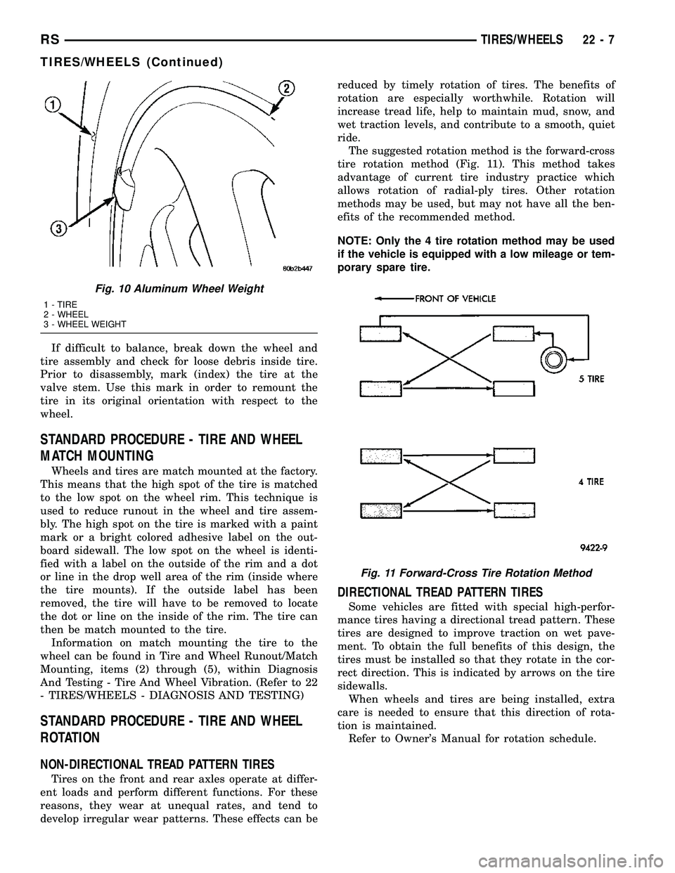
The aluminum wheels on this vehicle use a unique
wheel weight (Fig. 10). This wheel weight is designed
to fit the contoured surface of the wheel (Fig. 10).
When balancing an aluminum wheel, this wheel
weight must be used. Do not use any other type of
wheel weight. It will not properly fit the contour of
the wheel.
Always verify the Balance. When using off-vehicle
equipment, rotate assembly 180 degrees on balance
equipment to verify balance. Variation should not be
more than 0.125 (
1¤8) ounce. If variation is more than
0.125 ounce, balancing equipment could be malfunc-
tioning.
RSTIRES/WHEELS22-5
TIRES/WHEELS (Continued)
Page 1763 of 2339
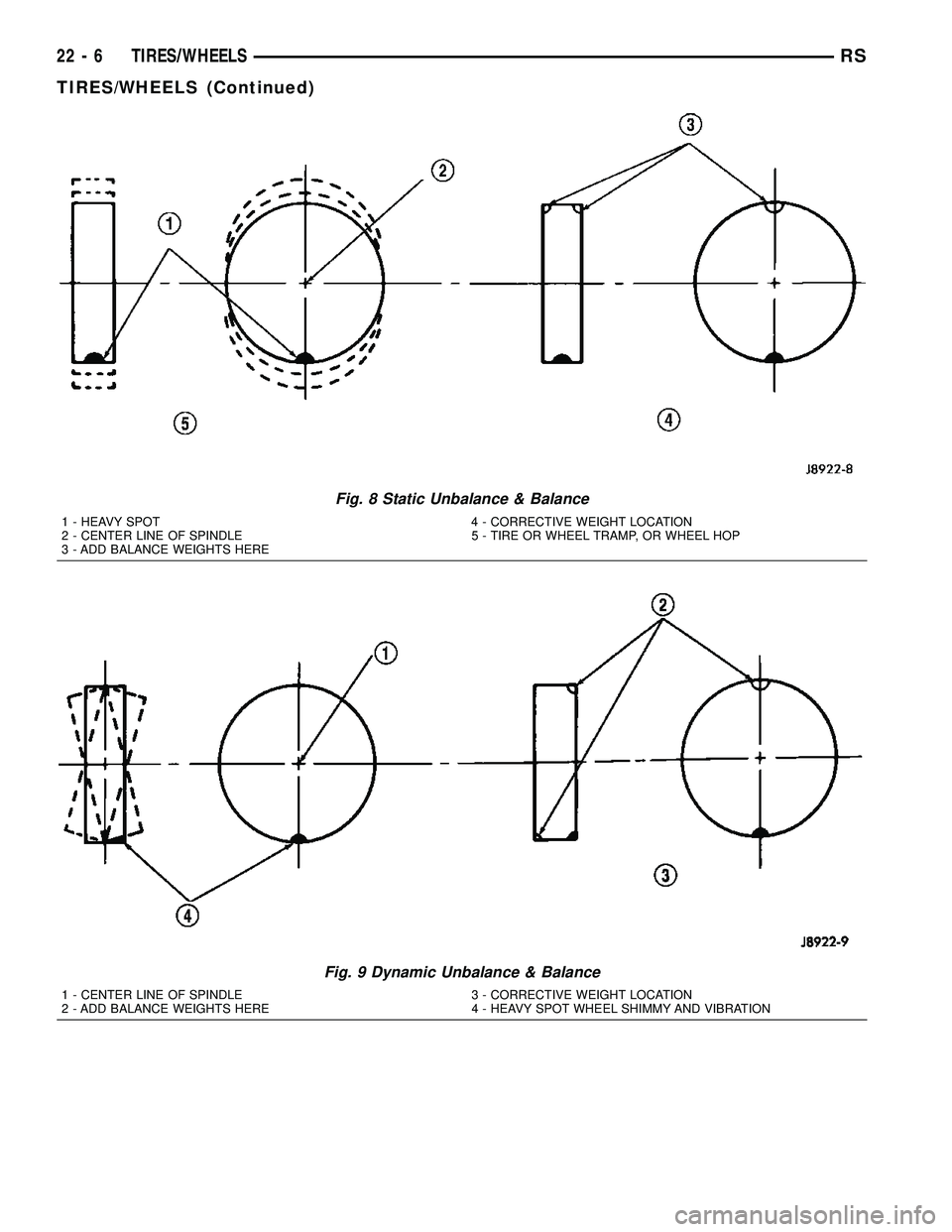
Fig. 8 Static Unbalance & Balance
1 - HEAVY SPOT 4 - CORRECTIVE WEIGHT LOCATION
2 - CENTER LINE OF SPINDLE 5 - TIRE OR WHEEL TRAMP, OR WHEEL HOP
3 - ADD BALANCE WEIGHTS HERE
Fig. 9 Dynamic Unbalance & Balance
1 - CENTER LINE OF SPINDLE 3 - CORRECTIVE WEIGHT LOCATION
2 - ADD BALANCE WEIGHTS HERE 4 - HEAVY SPOT WHEEL SHIMMY AND VIBRATION
22 - 6 TIRES/WHEELSRS
TIRES/WHEELS (Continued)
Page 1764 of 2339
If difficult to balance, break down the wheel and
tire assembly and check for loose debris inside tire.
Prior to disassembly, mark (index) the tire at the
valve stem. Use this mark in order to remount the
tire in its original orientation with respect to the
wheel.
STANDARD PROCEDURE - TIRE AND WHEEL
MATCH MOUNTING
Wheels and tires are match mounted at the factory.
This means that the high spot of the tire is matched
to the low spot on the wheel rim. This technique is
used to reduce runout in the wheel and tire assem-
bly. The high spot on the tire is marked with a paint
mark or a bright colored adhesive label on the out-
board sidewall. The low spot on the wheel is identi-
fied with a label on the outside of the rim and a dot
or line in the drop well area of the rim (inside where
the tire mounts). If the outside label has been
removed, the tire will have to be removed to locate
the dot or line on the inside of the rim. The tire can
then be match mounted to the tire.
Information on match mounting the tire to the
wheel can be found in Tire and Wheel Runout/Match
Mounting, items (2) through (5), within Diagnosis
And Testing - Tire And Wheel Vibration. (Refer to 22
- TIRES/WHEELS - DIAGNOSIS AND TESTING)
STANDARD PROCEDURE - TIRE AND WHEEL
ROTATION
NON-DIRECTIONAL TREAD PATTERN TIRES
Tires on the front and rear axles operate at differ-
ent loads and perform different functions. For these
reasons, they wear at unequal rates, and tend to
develop irregular wear patterns. These effects can bereduced by timely rotation of tires. The benefits of
rotation are especially worthwhile. Rotation will
increase tread life, help to maintain mud, snow, and
wet traction levels, and contribute to a smooth, quiet
ride.
The suggested rotation method is the forward-cross
tire rotation method (Fig. 11). This method takes
advantage of current tire industry practice which
allows rotation of radial-ply tires. Other rotation
methods may be used, but may not have all the ben-
efits of the recommended method.
NOTE: Only the 4 tire rotation method may be used
if the vehicle is equipped with a low mileage or tem-
porary spare tire.
DIRECTIONAL TREAD PATTERN TIRES
Some vehicles are fitted with special high-perfor-
mance tires having a directional tread pattern. These
tires are designed to improve traction on wet pave-
ment. To obtain the full benefits of this design, the
tires must be installed so that they rotate in the cor-
rect direction. This is indicated by arrows on the tire
sidewalls.
When wheels and tires are being installed, extra
care is needed to ensure that this direction of rota-
tion is maintained.
Refer to Owner's Manual for rotation schedule.
Fig. 10 Aluminum Wheel Weight
1 - TIRE
2 - WHEEL
3 - WHEEL WEIGHT
Fig. 11 Forward-Cross Tire Rotation Method
RSTIRES/WHEELS22-7
TIRES/WHEELS (Continued)
Page 1775 of 2339
CLEANING - TIRES
Before delivery of a vehicle, remove the protective
coating on the tires with white sidewalls or raised
white letters. To remove the protective coating, apply
warm water and let it soak for a few minutes. After-
wards, scrub the coating away with a soft bristle
brush. Steam cleaning may also be used to remove
the coating.
CAUTION: DO NOT use gasoline, mineral oil, oil-
based solvent or a wire brush for cleaning.
WHEELS
DESCRIPTION - WHEEL
Original equipment wheels are designed for proper
operation at all loads up to the specified maximum
vehicle capacity.
All models use either steel or aluminum drop-cen-
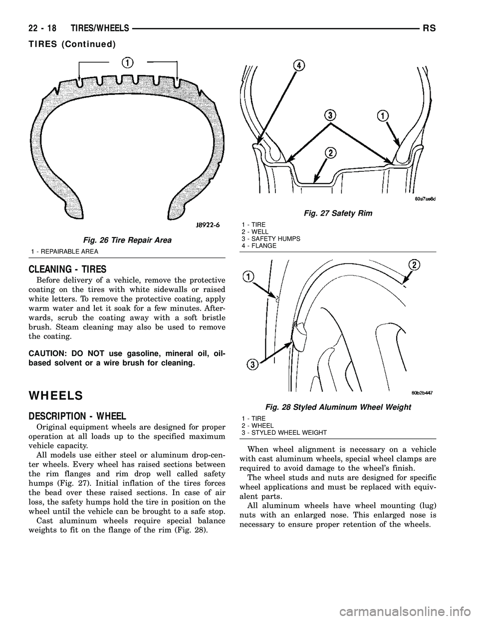
ter wheels. Every wheel has raised sections between
the rim flanges and rim drop well called safety
humps (Fig. 27). Initial inflation of the tires forces
the bead over these raised sections. In case of air
loss, the safety humps hold the tire in position on the
wheel until the vehicle can be brought to a safe stop.
Cast aluminum wheels require special balance
weights to fit on the flange of the rim (Fig. 28).When wheel alignment is necessary on a vehicle
with cast aluminum wheels, special wheel clamps are
required to avoid damage to the wheel's finish.
The wheel studs and nuts are designed for specific
wheel applications and must be replaced with equiv-
alent parts.
All aluminum wheels have wheel mounting (lug)
nuts with an enlarged nose. This enlarged nose is
necessary to ensure proper retention of the wheels.
Fig. 26 Tire Repair Area
1 - REPAIRABLE AREA
Fig. 27 Safety Rim
1 - TIRE
2 - WELL
3 - SAFETY HUMPS
4 - FLANGE
Fig. 28 Styled Aluminum Wheel Weight
1 - TIRE
2 - WHEEL
3 - STYLED WHEEL WEIGHT
22 - 18 TIRES/WHEELSRS
TIRES (Continued)
Page 2216 of 2339
PLUMBING - FRONT
DESCRIPTION
CAUTION: The system must be completely empty
before opening any fitting or connection in the
refrigeration system. Open fittings with caution
even after the system has been emptied. If any
pressure is noticed as a fitting is loosened,
retighten fitting and evacuate the system again.
The use of correct wrenches when making connec-
tions is very important. Improper wrenches or
improper use of wrenches can damage the fittings.
The internal parts of the A/C system will remain sta-
ble as long as moisture-free refrigerant and refrig-
erant oil is used. Abnormal amounts of dirt,
moisture or air can upset the chemical stability.
This may cause operational troubles or even seri-
ous damage if present in more than very small
quantities. Before disconnecting a refrigerant line
or hose, clean the outside of the fittings thoroughly
to prevent contamination from entering the refriger-
ant system.
When opening a refrigeration system, have every-
thing you will need to repair the system ready to
minimize the amount of time the system is opened.
Cap or plug all refrigerant line fittings as soon as
they are opened. This will help prevent the entrance
of dirt and moisture. All new lines and components
should be capped or sealed until they are ready to
be used. Before connecting a refrigerant line or
hose, clean the outside of the fittings thoroughly to
prevent contamination from entering the refrigerant
system.
All tools, including the refrigerant dispensing mani-
fold, manifold gauge set and test hoses should be
kept clean and dry.
The A/C refrigerant lines and hoses are used to
carry the refrigerant between the various A/C system
components. The refrigerant lines and hoses for the
R-134a system on this vehicle consist of a barrier-
hose design with a nylon tube sandwiched between
rubber layers. The nylon tube helps to contain the
R-134a refrigerant, which has a smaller molecular
structure than R-12 refrigerant. The ends of the
refrigerant lines are made from lightweight alumi-
num or steel, and commonly use braze-less fittings.Any kinks or sharp bends in the refrigerant lines
and hoses will reduce the capacity of the entire A/C
system and can reduce the flow of refrigerant in the
system. The radius of all bends in the flexible hose
refrigerant lines should be at least ten times the
diameter of the hose and the refrigerant lines should
be routed so they are at least 80 millimeters (3
inches) away from the exhaust manifold(s) and
exhaust pipe(s).
OPERATION
High pressures are produced in the refrigerant sys-
tem when the A/C compressor is operating. Extreme
care must be exercised to make sure that each of the
refrigerant system connections is pressure-tight and
leak free. It is a good practice to inspect all flexible
hose refrigerant lines at least once a year to make
sure they are in good condition and properly routed.
The refrigerant lines and hoses are coupled to
other A/C system components with block-type fit-
tings. An O-ring seal, or a flat steel gasket with an
integral O-ring (dual plane seal), is used to mate the
refrigerant line fittings with A/C system components
to ensure the integrity of the refrigerant system.
The refrigerant lines and hoses cannot be repaired
and, if faulty or damaged, they must be replaced.
WARNING
ENGINE COOLING SYSTEM
WARNING: THE ENGINE COOLING SYSTEM IS
DESIGNED TO DEVELOP INTERNAL PRESSURES
OF 97 TO 123 KILOPASCALS (14 TO 18 POUNDS
PER SQUARE INCH). DO NOT REMOVE OR
LOOSEN THE COOLANT PRESSURE CAP, CYLIN-
DER BLOCK DRAIN PLUGS, RADIATOR DRAIN,
RADIATOR HOSES, HEATER HOSES, OR HOSE
CLAMPS WHILE THE ENGINE COOLING SYSTEM IS
HOT AND UNDER PRESSURE. FAILURE TO
OBSERVE THIS WARNING CAN RESULT IN SERI-
OUS BURNS FROM THE HEATED ENGINE COOL-
ANT. ALLOW THE VEHICLE TO COOL FOR A
MINIMUM OF 15 MINUTES BEFORE OPENING THE
COOLING SYSTEM FOR SERVICE.
RSPLUMBING - FRONT24-65