2005 CHRYSLER CARAVAN parking brake
[x] Cancel search: parking brakePage 572 of 2339

DESCRIPTION - CONNECTOR, GROUND AND
SPLICE INFORMATION
CAUTION: Not all connectors are serviced. Some
connectors are serviced only with a harness. A typ-
ical example might be the Supplemental Restraint
System connectors. Always check parts availability
before attempting a repair.
IDENTIFICATION
In-line connectors are identified by a number, as
follows:
²In-line connectors located in the engine compart-
ment are C100 series numbers
²In-line connectors located in the Instrument
Panel area are C200 series numbers.
²In-line connectors located in the body are C300
series numbers.
²Jumper harness connectors are C400 series
numbers.
²Grounds and ground connectors are identified
with a ªGº and follow the same series numbering as
the in-line connectors.
²Splices are identified with an ªSº and follow the
same series numbering as the in-line connectors.
²Component connectors are identified by the com-
ponent name instead of a number. Multiple connec-
tors on a component use a C1, C2, etc. identifier.
LOCATIONS
Section 8W-91 contains connector/ground/splice
location illustrations. The illustrations contain the
connector name (or number)/ground number/splice
number and component identification. Connector/
ground/splice location charts in section 8W-91 refer-
ence the figure numbers of the illustrations.
The abbreviation T/O is used in the component
location section to indicate a point in which the wir-
ing harness branches out to a component. The abbre-
viation N/S means Not Shown in the illustrations
WARNING
WARNINGS - GENERAL
WARNINGSprovide information to prevent per-
sonal injury and vehicle damage. Below is a list of
general warnings that should be followed any time a
vehicle is being serviced.
WARNING: ALWAYS WEAR SAFETY GLASSES FOR
EYE PROTECTION.
WARNING: USE SAFETY STANDS ANYTIME A PRO-
CEDURE REQUIRES BEING UNDER A VEHICLE.WARNING: BE SURE THAT THE IGNITION SWITCH
ALWAYS IS IN THE OFF POSITION, UNLESS THE
PROCEDURE REQUIRES IT TO BE ON.
WARNING: SET THE PARKING BRAKE WHEN
WORKING ON ANY VEHICLE. AN AUTOMATIC
TRANSMISSION SHOULD BE IN PARK. A MANUAL
TRANSMISSION SHOULD BE IN NEUTRAL.
WARNING: OPERATE THE ENGINE ONLY IN A
WELL-VENTILATED AREA.
WARNING: KEEP AWAY FROM MOVING PARTS
WHEN THE ENGINE IS RUNNING, ESPECIALLY THE
FAN AND BELTS.
WARNING: TO PREVENT SERIOUS BURNS, AVOID
CONTACT WITH HOT PARTS SUCH AS THE RADIA-
TOR, EXHAUST MANIFOLD(S), TAIL PIPE, CATA-
LYTIC CONVERTER AND MUFFLER.
WARNING: DO NOT ALLOW FLAME OR SPARKS
NEAR THE BATTERY. GASES ARE ALWAYS
PRESENT IN AND AROUND THE BATTERY.
WARNING: ALWAYS REMOVE RINGS, WATCHES,
LOOSE HANGING JEWELRY AND AVOID LOOSE
CLOTHING.
DIAGNOSIS AND TESTING - WIRING HARNESS
TROUBLESHOOTING TOOLS
When diagnosing a problem in an electrical circuit
there are several common tools necessary. These tools
are listed and explained below.
²Jumper Wire - This is a test wire used to con-
nect two points of a circuit. It can be used to bypass
an open in a circuit.
WARNING: NEVER USE A JUMPER WIRE ACROSS
A LOAD, SUCH AS A MOTOR, CONNECTED
BETWEEN A BATTERY FEED AND GROUND.
²Voltmeter - Used to check for voltage on a cir-
cuit. Always connect the black lead to a known good
ground and the red lead to the positive side of the
circuit.
CAUTION: Most of the electrical components used
in today's vehicles are Solid State. When checking
voltages in these circuits, use a meter with a 10 -
megohm or greater impedance rating.
RS8W-01 WIRING DIAGRAM INFORMATION8W-01-7
WIRING DIAGRAM INFORMATION (Continued)
Page 583 of 2339

Component Page
Ignition Coil......................... 8W-30
Ignition Switch....................... 8W-10
Impact Sensors....................... 8W-43
Inlet Air Temperature Sensor............ 8W-30
Instrument Cluster.................... 8W-40
Instrument Panel Switch
Bank.................. 8W-43, 44, 52, 53, 63
Integrated Power Module............... 8W-10
Knock Sensor........................ 8W-30
Lamp Assemblies...................... 8W-51
License Lamp..................... 8W-51, 61
Lift Pump Motor...................... 8W-30
Lift Pump Relay...................... 8W-30
Liftgate Ajar Switch................ 8W-39, 61
Liftgate Cinch/Release Motor............ 8W-61
Liftgate Flood Lamps.................. 8W-44
Liftgate Pinch Sensors................. 8W-61
Low Beam Lamps..................... 8W-50
Manifold Absolute Pressure Sensor........ 8W-30
Mass Air Flow Sensor.................. 8W-30
Memory Seat/Mirror/Adjustable Pedals
Module...................... 8W-56, 62, 63
Memory Set Switch.................... 8W-63
Message Center.................... 8W-40, 46
Mode Door Actuator................... 8W-42
Multi-Function Switch............ 8W-50, 52, 53
Natural Vacuum Leak Detection Assembly . . 8W-30
Occupant Classification Module.......... 8W-43
Occupant Restraint Controller........... 8W-43
Overhead Console..................... 8W-49
Oxygen Sensors....................... 8W-30
Park Assist Display.................... 8W-56
Park Assist Module.................... 8W-56
Park Assist Sensors.................... 8W-56
Park Lamp Relay..................... 8W-10
Park Lamps.......................... 8W-50
Park/Turn Signal Lamps................ 8W-50
Parking Brake Switch.................. 8W-40
Power Folding Mirror Switch............ 8W-62
Power Liftgate Module................. 8W-61
Power Liftgate Motor.................. 8W-61
Power Mirror Switch................... 8W-62
Power Mirrors........................ 8W-62
Power Outlets........................ 8W-41
Power Seat Circuit Breaker.............. 8W-10
Power Seat Motors.................... 8W-63
Power Seat Position Sensors............. 8W-63
Power Seat Switches................... 8W-63
Power Window Circuit Breaker........... 8W-10
Power Window Motors.................. 8W-60
Power Window Switches................ 8W-60
Powertrain Control Module........... 8W-30, 31
PTCs............................... 8W-10
Radiator Fan Relaies................... 8W-42Component Page
Radiator Fans........................ 8W-42
Radio............................... 8W-47
Reading Lamps....................... 8W-44
Rear A/C-Heater Unit.................. 8W-42
Rear Auto Temp Control Switch.......... 8W-42
Rear Blower Control Switches............ 8W-42
Rear Blower Motor Power Module......... 8W-42
Rear Dome Lamp..................... 8W-44
Rear Intrusion Sensor.................. 8W-39
Rear Mode Motor..................... 8W-42
Rear Temperature Motor................ 8W-42
Rear View Mirror................ 8W-49, 55, 62
Rear Window Defogger Grid............. 8W-48
Rear Wiper Motor..................... 8W-53
Recirculation Door Actuator............. 8W-42
Remote Radio Switches................. 8W-47
Repeater Lamps...................... 8W-52
Seat Belt Switches.................... 8W-43
Seat Belt Tensioners................... 8W-43
Seat Weight Sensor.................... 8W-43
Sentry Key Remote Entry Module......... 8W-39
Siren............................... 8W-39
Sliding Door Control Modules............ 8W-61
Sliding Door Latch Sensing Switches...... 8W-61
Sliding Door Lock Motors............... 8W-61
Sliding Door Motors................... 8W-61
Speakers............................ 8W-47
Speed Control Servo................... 8W-33
Speed Control Switches................. 8W-33
Speed Sensors........................ 8W-31
Splices.............................. 8W-70
Starter Motor........................ 8W-21
Starter Motor Relay................... 8W-21
Sunroof Module....................... 8W-64
Sunroof Switch....................... 8W-64
Thatcham Alarm Indicator.............. 8W-39
Thatcham Alarm Module................ 8W-39
Throttle Position Sensor................ 8W-30
Traction Control Switch................. 8W-35
Trailer Tow Connector.................. 8W-54
Transmission Control Module............ 8W-31
Transmission Control Relay............. 8W-31
Transmission Range Sensor.............. 8W-31
Transmission Solenoid/Pressure Switch
Assembly.......................... 8W-31
Turn Signal Lamps.................... 8W-52
Vehicle Speed Sensor................... 8W-30
Vent Motors.......................... 8W-60
Visor/Vanity Lamps.................... 8W-44
Washer Fluid Level Switch.............. 8W-53
Washer Pump Motor................... 8W-53
Water In Fuel Sensor.................. 8W-30
Wheel Speed Sensors................... 8W-35
Wiper Module........................ 8W-53
8W - 02 - 2 8W-02 COMPONENT INDEXRS
Page 768 of 2339

8W-40 INSTRUMENT CLUSTER
Component Page
Body Control Module............... 8W-40-3, 4
Fuse 24............................ 8W-40-2
G200.............................. 8W-40-4
Instrument Cluster............. 8W-40-2, 3, 4, 5Component Page
Integrated Power Module.............. 8W-40-2
Message Center..................... 8W-40-5
Occupant Restraint Controller.......... 8W-40-3
Parking Brake Switch................ 8W-40-5
RS8W-40 INSTRUMENT CLUSTER8W-40-1
Page 1419 of 2339

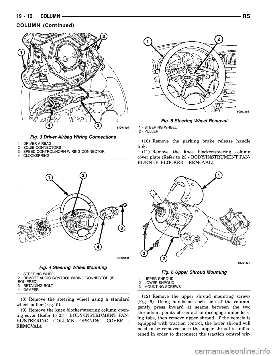
(8) Remove the steering wheel using a standard
wheel puller (Fig. 5).
(9) Remove the knee blocker/steering column open-
ing cover (Refer to 23 - BODY/INSTRUMENT PAN-
EL/STEERING COLUMN OPENING COVER -
REMOVAL).(10) Remove the parking brake release handle
link.
(11) Remove the knee blocker/steering column
cover plate (Refer to 23 - BODY/INSTRUMENT PAN-
EL/KNEE BLOCKER - REMOVAL).
(12) Remove the upper shroud mounting screws
(Fig. 6). Using hands on each side of the column,
gently press inward at seams between the two
shrouds at points of contact to disengage inner lock-
ing tabs, then remove upper shroud. If the vehicle is
equipped with traction control, the lower shroud will
need to be removed once the upper shroud is unfas-
tened in order to disconnect the traction control wir-
Fig. 3 Driver Airbag Wiring Connections
1 - DRIVER AIRBAG
2 - SQUIB CONNECTORS
3 - SPEED CONTROL/HORN WIRING CONNECTOR
4 - CLOCKSPRING
Fig. 4 Steering Wheel Mounting
1 - STEERING WHEEL
2 - REMOTE AUDIO CONTROL WIRING CONNECTOR (IF
EQUIPPED)
3 - RETAINING BOLT
4 - DAMPER
Fig. 5 Steering Wheel Removal
1 - STEERING WHEEL
2 - PULLER
Fig. 6 Upper Shroud Mounting
1 - UPPER SHROUD
2 - LOWER SHROUD
3 - MOUNTING SCREWS
19 - 12 COLUMNRS
COLUMN (Continued)
Page 1424 of 2339

(19) Position the lower shroud on the column (Fig.
8). Install the lower shroud mounting screw. Tighten
the screw to 2 N´m (17 in. lbs.) torque.
(20) If equipped with adjustable pedals, Connect
the wiring connector for the switch (Fig. 7) to the col-
umn wiring harness.
(21) Position the upper shroud on top of the lower
shroud and snap it into place. Install the upper
shroud mounting screws (Fig. 6). Tighten the screws
to 2 N´m (17 in. lbs.) torque.
(22) Inspect shroud mating surfaces for excessive
gaps and correct as necessary.
(23) Install the cluster trim bezel (Refer to 23 -
BODY/INSTRUMENT PANEL/CLUSTER BEZEL -
INSTALLATION).
(24) Install the knee blocker/steering column cover
plate. (Refer to 23 - BODY/INSTRUMENT PANEL/
KNEE BLOCKER - INSTALLATION)
(25) Install the parking brake handle link.
(26) Install the knee blocker/steering column open-
ing cover. (Refer to 23 - BODY/INSTRUMENT PAN-
EL/STEERING COLUMN OPENING COVER -
INSTALLATION)
(27) Align the splines and install the steering
wheel on the steering column shaft(Refer to 19 -
STEERING/COLUMN/STEERING WHEEL -
INSTALLATION).
(28) Install the damper over the steering column
shaft (Fig. 4).
(29) Install the steering wheel retaining bolt (Fig.
4). Tighten the bolt to 61 N´m (45 ft. lbs.) torque.
(30) If the steering wheel is equipped with remote
audio controls, connect the wiring connector to the
clockspring (Fig. 4).
(31) Connect the two squib connectors to the
driver airbag (Fig. 3). The connectors are color coded
to avoid connector mix-up.
(32) Connect the speed control and horn connector
to the clockspring (Fig. 3).
(33) Install the airbag to the steering wheel.
Install the driver airbag mounting screws (Fig. 2).
Tighten screws to 10 N´m (90 in. lbs.) torque.
(34) Connect the battery negative (ground) cable to
battery post following special Diagnosis And Testing
procedure. (Refer to 8 - ELECTRICAL/RESTRAINTS
- DIAGNOSIS AND TESTING)
(35) Check operation of all steering column
mounted components.
(36) Road test vehicle to ensure proper operation
of steering.SPECIFICATIONS
COLUMN FASTENER TORQUE
DESCRIPTION N´mFt.
Lbs.In.
Lbs.
Driver Airbag Mounting Screws 10 Ð 90
Multi-Function Switch Mounting
Housing Set-Screw14 Ð 124
Shroud Attaching Screws - Fixed 3 Ð 23
Shroud Attaching Screws -
Lower/Upper2Ð17
SKIM Attaching Screw 4 Ð 30
Steering Column Coupling Pinch
Bolt28 Ð 250
Steering Column Mounting Nuts 12 Ð 105
Steering Wheel Retaining Bolt 61 45 Ð
IGNITION SWITCH
REMOVAL
The ignition switch attaches to the lock cylinder
housing on the end opposite the lock cylinder (Fig.
20). For ignition switch terminal and circuit identifi-
cation, refer to the appropriate wiring information.
The wiring information includes wiring diagrams,
proper wire and connector repair procedures, further
details on wire harness routing and retention, as well
as pin-out and location views for the various wire
harness connectors, splices and grounds.
(1) Disconnect negative cable from battery.
Fig. 20 Ignition SwitchÐViewed From Below
Column
1 - IGNITION SWITCH
2 - LOCK CYLINDER HOUSING
3 - RETAINING TABS
RSCOLUMN19-17
COLUMN (Continued)
Page 1425 of 2339

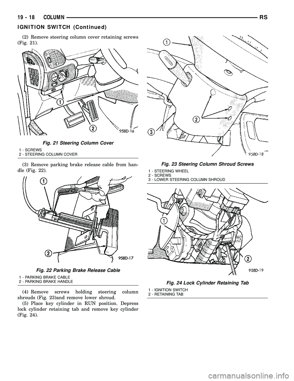
(2) Remove steering column cover retaining screws
(Fig. 21).
(3) Remove parking brake release cable from han-
dle (Fig. 22).
(4) Remove screws holding steering column
shrouds (Fig. 23)and remove lower shroud.
(5) Place key cylinder in RUN position. Depress
lock cylinder retaining tab and remove key cylinder
(Fig. 24).
Fig. 21 Steering Column Cover
1 - SCREWS
2 - STEERING COLUMN COVER
Fig. 22 Parking Brake Release Cable
1 - PARKING BRAKE CABLE
2 - PARKING BRAKE HANDLE
Fig. 23 Steering Column Shroud Screws
1 - STEERING WHEEL
2 - SCREWS
3 - LOWER STEERING COLUMN SHROUD
Fig. 24 Lock Cylinder Retaining Tab
1 - IGNITION SWITCH
2 - RETAINING TAB
19 - 18 COLUMNRS
IGNITION SWITCH (Continued)
Page 1543 of 2339

FLUID
STANDARD PROCEDURE
FLUID LEVEL AND CONDITION CHECK
NOTE: Only transmission fluid of the type labeled
Mopar ATF+4 (Automatic Transmission Fluid)
should be used in this transaxle.
FLUID LEVEL CHECK
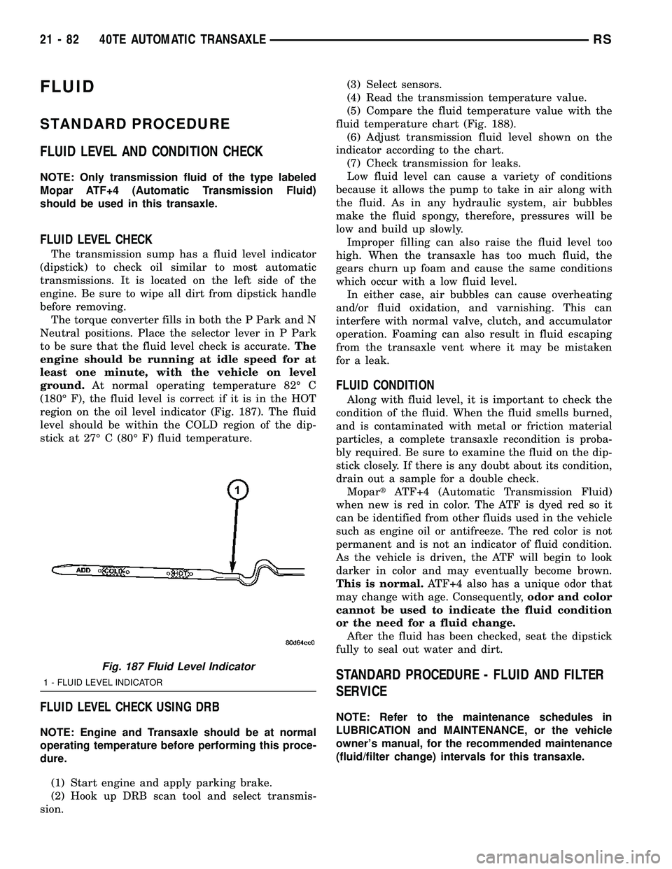
The transmission sump has a fluid level indicator
(dipstick) to check oil similar to most automatic
transmissions. It is located on the left side of the
engine. Be sure to wipe all dirt from dipstick handle
before removing.
The torque converter fills in both the P Park and N
Neutral positions. Place the selector lever in P Park
to be sure that the fluid level check is accurate.The
engine should be running at idle speed for at
least one minute, with the vehicle on level
ground.At normal operating temperature 82É C
(180É F), the fluid level is correct if it is in the HOT
region on the oil level indicator (Fig. 187). The fluid
level should be within the COLD region of the dip-
stick at 27É C (80É F) fluid temperature.
FLUID LEVEL CHECK USING DRB
NOTE: Engine and Transaxle should be at normal
operating temperature before performing this proce-
dure.
(1) Start engine and apply parking brake.
(2) Hook up DRB scan tool and select transmis-
sion.(3) Select sensors.
(4) Read the transmission temperature value.
(5) Compare the fluid temperature value with the
fluid temperature chart (Fig. 188).
(6) Adjust transmission fluid level shown on the
indicator according to the chart.
(7) Check transmission for leaks.
Low fluid level can cause a variety of conditions
because it allows the pump to take in air along with
the fluid. As in any hydraulic system, air bubbles
make the fluid spongy, therefore, pressures will be
low and build up slowly.
Improper filling can also raise the fluid level too
high. When the transaxle has too much fluid, the
gears churn up foam and cause the same conditions
which occur with a low fluid level.
In either case, air bubbles can cause overheating
and/or fluid oxidation, and varnishing. This can
interfere with normal valve, clutch, and accumulator
operation. Foaming can also result in fluid escaping
from the transaxle vent where it may be mistaken
for a leak.
FLUID CONDITION
Along with fluid level, it is important to check the
condition of the fluid. When the fluid smells burned,
and is contaminated with metal or friction material
particles, a complete transaxle recondition is proba-
bly required. Be sure to examine the fluid on the dip-
stick closely. If there is any doubt about its condition,
drain out a sample for a double check.
MopartATF+4 (Automatic Transmission Fluid)
when new is red in color. The ATF is dyed red so it
can be identified from other fluids used in the vehicle
such as engine oil or antifreeze. The red color is not
permanent and is not an indicator of fluid condition.
As the vehicle is driven, the ATF will begin to look
darker in color and may eventually become brown.
This is normal.ATF+4 also has a unique odor that
may change with age. Consequently,odor and color
cannot be used to indicate the fluid condition
or the need for a fluid change.
After the fluid has been checked, seat the dipstick
fully to seal out water and dirt.
STANDARD PROCEDURE - FLUID AND FILTER
SERVICE
NOTE: Refer to the maintenance schedules in
LUBRICATION and MAINTENANCE, or the vehicle
owner's manual, for the recommended maintenance
(fluid/filter change) intervals for this transaxle.
Fig. 187 Fluid Level Indicator
1 - FLUID LEVEL INDICATOR
21 - 82 40TE AUTOMATIC TRANSAXLERS
Page 1545 of 2339

(6) Start engine and allow to idle for at least one
minute. Then, with parking and service brakes
applied, move selector lever momentarily to each
position, ending in the park or neutral position.
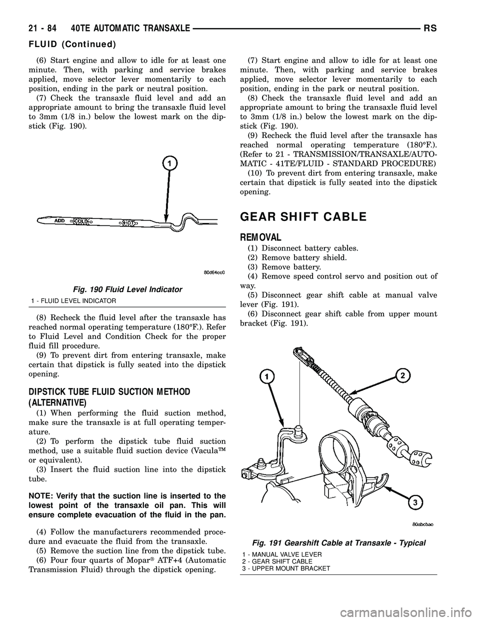
(7) Check the transaxle fluid level and add an
appropriate amount to bring the transaxle fluid level
to 3mm (1/8 in.) below the lowest mark on the dip-
stick (Fig. 190).
(8) Recheck the fluid level after the transaxle has
reached normal operating temperature (180ÉF.). Refer
to Fluid Level and Condition Check for the proper
fluid fill procedure.
(9) To prevent dirt from entering transaxle, make
certain that dipstick is fully seated into the dipstick
opening.
DIPSTICK TUBE FLUID SUCTION METHOD
(ALTERNATIVE)
(1) When performing the fluid suction method,
make sure the transaxle is at full operating temper-
ature.
(2) To perform the dipstick tube fluid suction
method, use a suitable fluid suction device (VaculaŸ
or equivalent).
(3) Insert the fluid suction line into the dipstick
tube.
NOTE: Verify that the suction line is inserted to the
lowest point of the transaxle oil pan. This will
ensure complete evacuation of the fluid in the pan.
(4) Follow the manufacturers recommended proce-
dure and evacuate the fluid from the transaxle.
(5) Remove the suction line from the dipstick tube.
(6) Pour four quarts of MopartATF+4 (Automatic
Transmission Fluid) through the dipstick opening.(7) Start engine and allow to idle for at least one
minute. Then, with parking and service brakes
applied, move selector lever momentarily to each
position, ending in the park or neutral position.
(8) Check the transaxle fluid level and add an
appropriate amount to bring the transaxle fluid level
to 3mm (1/8 in.) below the lowest mark on the dip-
stick (Fig. 190).
(9) Recheck the fluid level after the transaxle has
reached normal operating temperature (180ÉF.).
(Refer to 21 - TRANSMISSION/TRANSAXLE/AUTO-
MATIC - 41TE/FLUID - STANDARD PROCEDURE)
(10) To prevent dirt from entering transaxle, make
certain that dipstick is fully seated into the dipstick
opening.
GEAR SHIFT CABLE
REMOVAL
(1) Disconnect battery cables.
(2) Remove battery shield.
(3) Remove battery.
(4) Remove speed control servo and position out of
way.
(5) Disconnect gear shift cable at manual valve
lever (Fig. 191).
(6) Disconnect gear shift cable from upper mount
bracket (Fig. 191).
Fig. 190 Fluid Level Indicator
1 - FLUID LEVEL INDICATOR
Fig. 191 Gearshift Cable at Transaxle - Typical
1 - MANUAL VALVE LEVER
2 - GEAR SHIFT CABLE
3 - UPPER MOUNT BRACKET
21 - 84 40TE AUTOMATIC TRANSAXLERS
FLUID (Continued)