2005 CHRYSLER CARAVAN cooling
[x] Cancel search: coolingPage 1191 of 2339
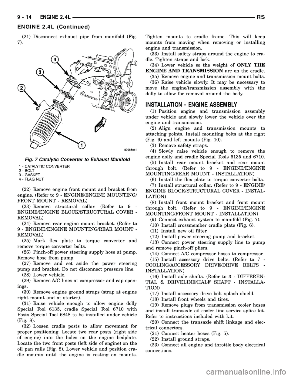
(21) Disconnect exhaust pipe from manifold (Fig.
7).
(22) Remove engine front mount and bracket from
engine. (Refer to 9 - ENGINE/ENGINE MOUNTING/
FRONT MOUNT - REMOVAL)
(23) Remove structural collar. (Refer to 9 -
ENGINE/ENGINE BLOCK/STRUCTURAL COVER -
REMOVAL)
(24) Remove rear engine mount bracket. (Refer to
9 - ENGINE/ENGINE MOUNTING/REAR MOUNT -
REMOVAL)
(25) Mark flex plate to torque converter and
remove torque converter bolts.
(26) Pinch-off power steering supply hose at pump.
Remove hose from pump.
(27) Remove and set aside the power steering
pump and bracket. Do not disconnect pressure line.
(28) Lower vehicle.
(29) Remove A/C lines at compressor and cap open-
ings.
(30) Remove engine ground straps (strap at engine
right mount and at starter).
(31) Raise vehicle enough to allow engine dolly
Special Tool 6135, cradle Special Tool 6710 with
Posts Special Tool 6848 to be installed under vehicle
(Fig. 8).
(32) Loosen cradle posts to allow movement for
proper positioning. Locate two rear posts (right side
of engine) into the holes on the engine bedplate.
Locate the two front posts (left side of engine) on the
oil pan rails (Fig. 8). Lower vehicle and position cra-
dle mounts until the engine is resting on mounts.Tighten mounts to cradle frame. This will keep
mounts from moving when removing or installing
engine and transmission.
(33) Install safety straps around the engine to cra-
dle. Tighten straps and lock.
(34) Lower vehicle so the weight ofONLY THE
ENGINE AND TRANSMISSIONare on the cradle.
(35) Remove engine and transmission mount bolts.
(36) Raise vehicle slowly. It may be necessary to
move the engine/transmission assembly with the
dolly to allow for removal around the body.
INSTALLATION - ENGINE ASSEMBLY
(1) Position engine and transmission assembly
under vehicle and slowly lower the vehicle over the
engine and transmission.
(2) Align engine and transmission mounts to
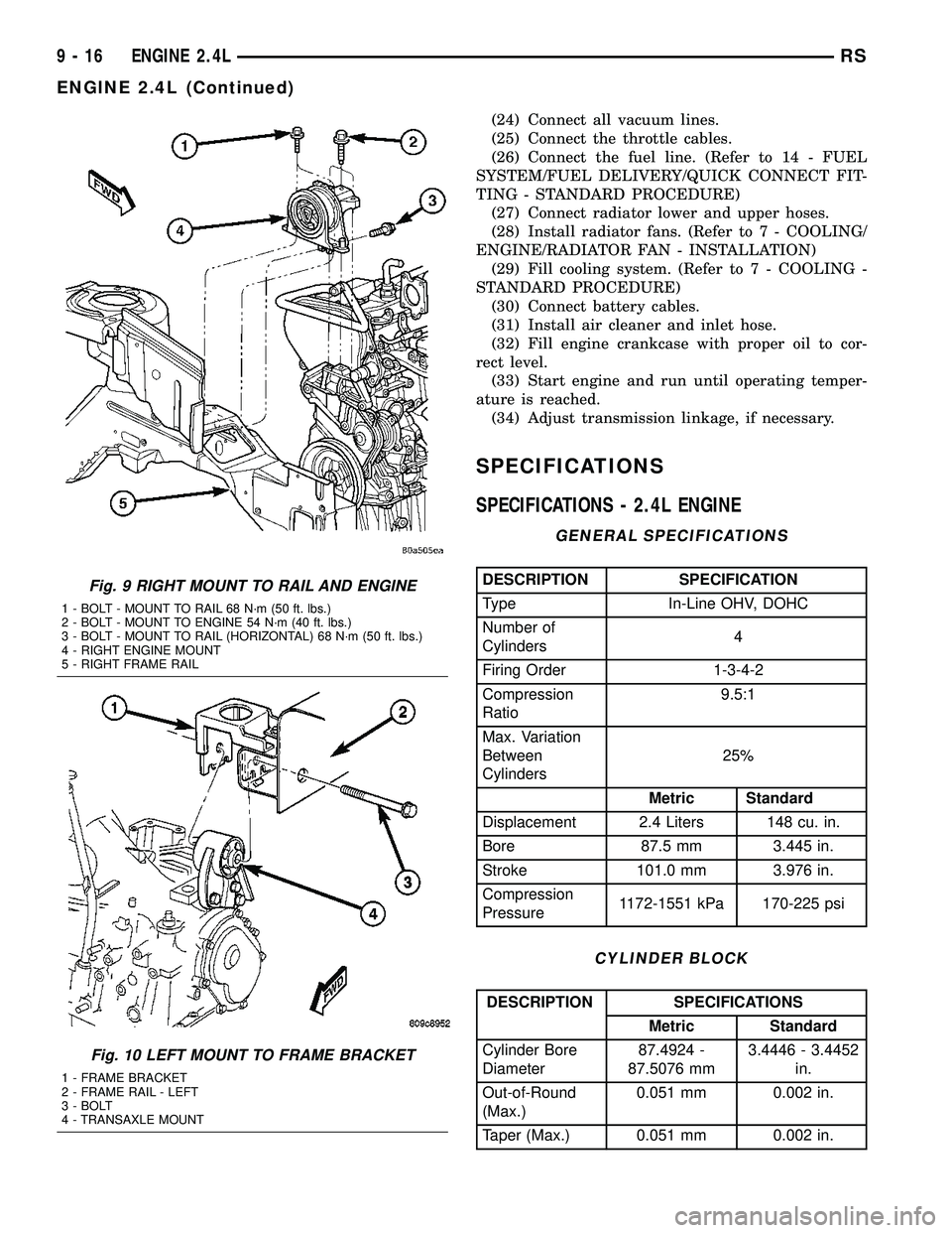
attaching points. Install mounting bolts at the right
(Fig. 9) and left mounts (Fig. 10).
(3) Remove safety straps.
(4) Slowly raise vehicle enough to remove the
engine dolly and cradle Special Tools 6135 and 6710.
(5) Install rear mount bracket and rear mount
through bolt. (Refer to 9 - ENGINE/ENGINE
MOUNTING/REAR MOUNT - INSTALLATION)
(6) Install the flex plate to torque converter bolts.
(7) Install structural collar. (Refer to 9 - ENGINE/
ENGINE BLOCK/STRUCTURAL COVER - INSTAL-
LATION)
(8) Install front mount bracket and front mount
through bolt. (Refer to 9 - ENGINE/ENGINE
MOUNTING/FRONT MOUNT - INSTALLATION)
(9) Connect exhaust system to manifold (Fig. 7).
(10) Install crossmember cradle plate (Fig. 6).
(11) Install new oil filter.
(12) Install power steering pump and bracket.
(13) Connect power steering supply line to pump
and remove pinch-off pliers.
(14) Connect A/C compressor hoses to compressor.
(15) Install accessory drive belts. (Refer to 7 -
COOLING/ACCESSORY DRIVE/DRIVE BELTS -
INSTALLATION)
(16) Install axle shafts. (Refer to 3 - DIFFEREN-
TIAL & DRIVELINE/HALF SHAFT - INSTALLA-
TION)
(17) Install accessory drive belt splash shield.
(18) Install front wheels and tires.
(19) Remove plugs from transmission cooler hoses
and install transaxle oil cooler line service splice kit.
Refer to instructions included with kit.
(20) Connect the transaxle shift linkage and elec-
trical connectors.
(21) Connect heater hoses (Fig. 5).
(22) Install ground straps.
(23) Connect all engine and throttle body electrical
connections.
Fig. 7 Catalytic Converter to Exhaust Manifold
1 - CATALYTIC CONVERTER
2 - BOLT
3 - GASKET
4 - FLAG NUT
9 - 14 ENGINE 2.4LRS
ENGINE 2.4L (Continued)
Page 1193 of 2339
(24) Connect all vacuum lines.
(25) Connect the throttle cables.
(26) Connect the fuel line. (Refer to 14 - FUEL
SYSTEM/FUEL DELIVERY/QUICK CONNECT FIT-
TING - STANDARD PROCEDURE)
(27) Connect radiator lower and upper hoses.
(28) Install radiator fans. (Refer to 7 - COOLING/
ENGINE/RADIATOR FAN - INSTALLATION)
(29) Fill cooling system. (Refer to 7 - COOLING -
STANDARD PROCEDURE)
(30) Connect battery cables.
(31) Install air cleaner and inlet hose.
(32) Fill engine crankcase with proper oil to cor-
rect level.
(33) Start engine and run until operating temper-
ature is reached.
(34) Adjust transmission linkage, if necessary.
SPECIFICATIONS
SPECIFICATIONS - 2.4L ENGINE
GENERAL SPECIFICATIONS
DESCRIPTION SPECIFICATION
Type In-Line OHV, DOHC
Number of
Cylinders4
Firing Order 1-3-4-2
Compression
Ratio9.5:1
Max. Variation
Between
Cylinders25%
Metric Standard
Displacement 2.4 Liters 148 cu. in.
Bore 87.5 mm 3.445 in.
Stroke 101.0 mm 3.976 in.
Compression
Pressure1172-1551 kPa 170-225 psi
CYLINDER BLOCK
DESCRIPTION SPECIFICATIONS
Metric Standard
Cylinder Bore
Diameter87.4924 -
87.5076 mm3.4446 - 3.4452
in.
Out-of-Round
(Max.)0.051 mm 0.002 in.
Taper (Max.) 0.051 mm 0.002 in.
Fig. 9 RIGHT MOUNT TO RAIL AND ENGINE
1 - BOLT - MOUNT TO RAIL 68 N´m (50 ft. lbs.)
2 - BOLT - MOUNT TO ENGINE 54 N´m (40 ft. lbs.)
3 - BOLT - MOUNT TO RAIL (HORIZONTAL) 68 N´m (50 ft. lbs.)
4 - RIGHT ENGINE MOUNT
5 - RIGHT FRAME RAIL
Fig. 10 LEFT MOUNT TO FRAME BRACKET
1 - FRAME BRACKET
2 - FRAME RAIL - LEFT
3 - BOLT
4 - TRANSAXLE MOUNT
9 - 16 ENGINE 2.4LRS
ENGINE 2.4L (Continued)
Page 1203 of 2339
CYLINDER-TO-CYLINDER LEAKAGE TEST
To determine if an engine cylinder head gasket is
leaking between adjacent cylinders, follow the proce-
dures in Cylinder Compression Pressure Test (Refer
to 9 - ENGINE - DIAGNOSIS AND TESTING). An
engine cylinder head gasket leaking between adja-
cent cylinders will result in approximately a 50±70%
reduction in compression pressure.
CYLINDER-TO-WATER JACKET LEAKAGE TEST
WARNING: USE EXTREME CAUTION WHEN THE
ENGINE IS OPERATING WITH COOLANT PRES-
SURE CAP REMOVED.
VISUAL TEST METHOD
With the engine cool, remove the coolant pressure
cap. Start the engine and allow it to warm up until
thermostat opens.
If a large combustion/compression pressure leak
exists, bubbles will be visible in the coolant.
COOLING SYSTEM TESTER METHOD
WARNING: WITH COOLING SYSTEM TESTER IN
PLACE, PRESSURE WILL BUILD UP FAST. EXCES-
SIVE PRESSURE BUILT UP, BY CONTINUOUS
ENGINE OPERATION, MUST BE RELEASED TO A
SAFE PRESSURE POINT. NEVER PERMIT PRES-
SURE TO EXCEED 138 kPa (20 psi).
Install Cooling System Tester 7700 or equivalent to
pressure cap neck. Start the engine and observe the
tester's pressure gauge. If gauge pulsates with every
power stroke of a cylinder a combustion pressure
leak is evident.
CHEMICAL TEST METHOD
Combustion leaks into the cooling system can also
be checked by using Bloc-Chek Kit C-3685-A or
equivalent. Perform test following the procedures
supplied with the tool kit.
REMOVAL - CYLINDER HEAD
(1) Perform fuel system pressure release procedure
before attempting any repairs.(Refer to 14 -
FUEL SYSTEM/FUEL DELIVERY - SPECIFICA-
TIONS)
(2) Disconnect battery negative cable.
(3) Drain cooling system. (Refer to 7 - COOLING -
STANDARD PROCEDURE)
(4) Remove air filter housing and inlet tube.
(5) Remove upper intake manifold. (Refer to 9 -
ENGINE/MANIFOLDS/INTAKE MANIFOLD -
REMOVAL)(6) Remove heater tube support bracket from cyl-
inder head.
(7) Disconnect radiator upper and heater supply
hoses from intake manifold water outlet connections.
(8) Remove accessory drive belts. (Refer to 7 -
COOLING/ACCESSORY DRIVE/DRIVE BELTS -
REMOVAL)
(9) Raise vehicle and remove exhaust pipe from
manifold.
(10) Remove power steering pump reservoir and
line support bracket from lower intake manifold and
set aside. Do not disconnect lines.
(11) Remove ignition coil and wires from engine.
(12) Disconnect cam sensor and fuel injector wir-
ing connectors.
(13) Remove timing belt and camshaft sprockets.
(Refer to 9 - ENGINE/VALVE TIMING/TIMING
BELT/CHAIN AND SPROCKETS - REMOVAL)
(14) Remove timing belt idler pulley and rear tim-
ing belt cover. (Refer to 9 - ENGINE/VALVE TIM-
ING/TIMING BELT / CHAIN COVER(S) -
REMOVAL)
(15) Remove cylinder head cover. (Refer to 9 -
ENGINE/CYLINDER HEAD/CYLINDER HEAD
COVER(S) - REMOVAL)
(16) Remove camshafts (Refer to 9 - ENGINE/
CYLINDER HEAD/CAMSHAFT(S) - REMOVAL).
NOTE: Identify rocker arm position to ensure cor-
rect re-installation in original position, if reused.
(17) Remove rocker arms. (Refer to 9 - ENGINE/
CYLINDER HEAD/ROCKER ARMS - REMOVAL)
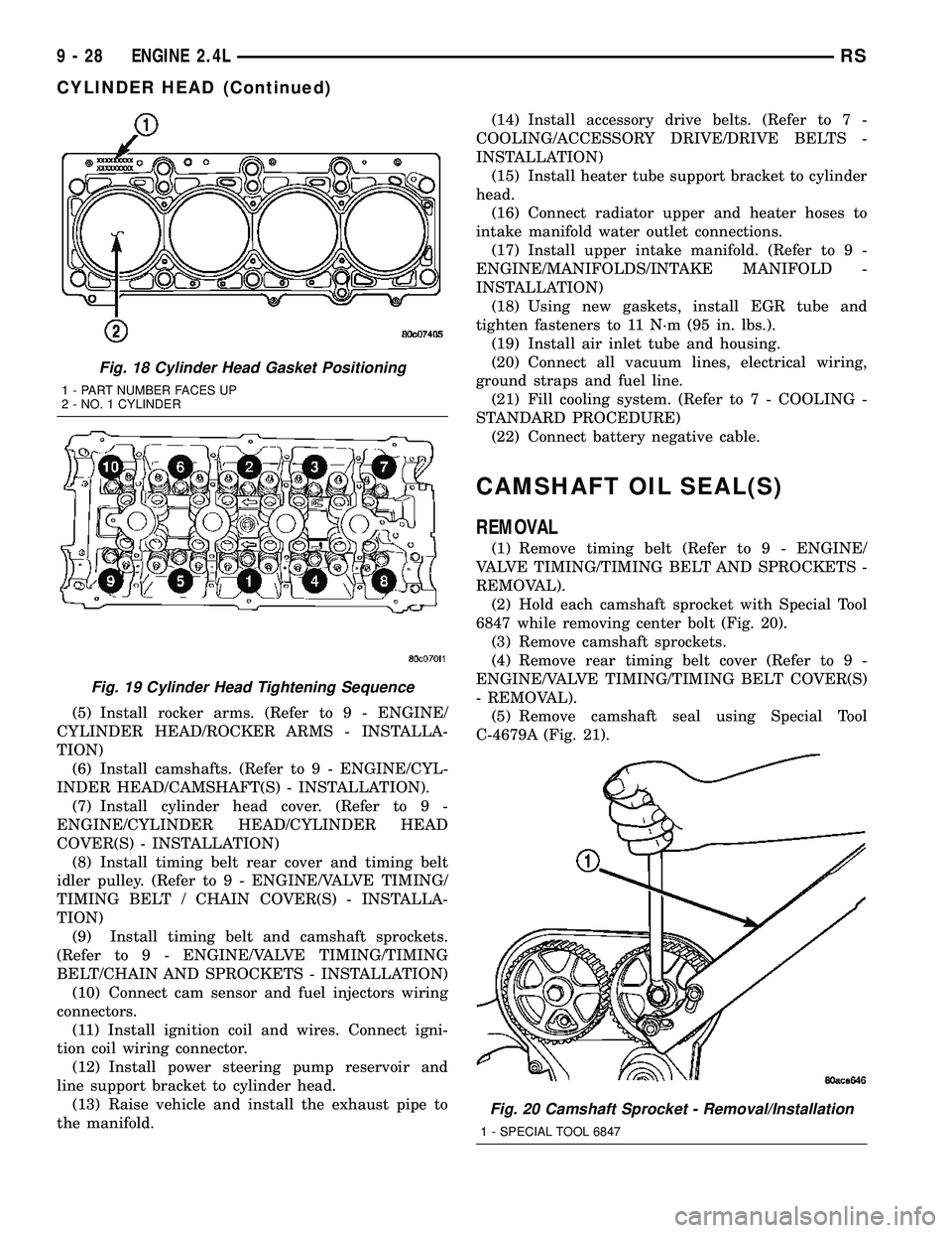
(18) Remove cylinder head bolts in REVERSE
sequence of tightening (Fig. 19).
(19) Remove cylinder head from engine block.
(20) Inspect and clean cylinder head. (Refer to 9 -
ENGINE/CYLINDER HEAD - INSPECTION) (Refer
to 9 - ENGINE/CYLINDER HEAD - CLEANING)
CLEANING
To ensure engine gasket sealing, proper surface
preparation must be performed, especially with the
use of aluminum engine components and multi-layer
steel cylinder head gaskets.
NOTE: Multi-Layer Steel (MLS) head gaskets require
a scratch free sealing surface.
Remove all gasket material from cylinder head and
block (Refer to 9 - ENGINE - STANDARD PROCE-
DURE). Be careful not to gouge or scratch the alumi-
num head sealing surface.
Clean all engine oil passages.
9 - 26 ENGINE 2.4LRS
CYLINDER HEAD (Continued)
Page 1205 of 2339
(5) Install rocker arms. (Refer to 9 - ENGINE/
CYLINDER HEAD/ROCKER ARMS - INSTALLA-
TION)
(6) Install camshafts. (Refer to 9 - ENGINE/CYL-
INDER HEAD/CAMSHAFT(S) - INSTALLATION).
(7) Install cylinder head cover. (Refer to 9 -
ENGINE/CYLINDER HEAD/CYLINDER HEAD
COVER(S) - INSTALLATION)
(8) Install timing belt rear cover and timing belt
idler pulley. (Refer to 9 - ENGINE/VALVE TIMING/
TIMING BELT / CHAIN COVER(S) - INSTALLA-
TION)
(9) Install timing belt and camshaft sprockets.
(Refer to 9 - ENGINE/VALVE TIMING/TIMING
BELT/CHAIN AND SPROCKETS - INSTALLATION)
(10) Connect cam sensor and fuel injectors wiring
connectors.
(11) Install ignition coil and wires. Connect igni-
tion coil wiring connector.
(12) Install power steering pump reservoir and
line support bracket to cylinder head.
(13) Raise vehicle and install the exhaust pipe to
the manifold.(14) Install accessory drive belts. (Refer to 7 -
COOLING/ACCESSORY DRIVE/DRIVE BELTS -
INSTALLATION)
(15) Install heater tube support bracket to cylinder
head.
(16) Connect radiator upper and heater hoses to
intake manifold water outlet connections.
(17) Install upper intake manifold. (Refer to 9 -
ENGINE/MANIFOLDS/INTAKE MANIFOLD -
INSTALLATION)
(18) Using new gaskets, install EGR tube and
tighten fasteners to 11 N´m (95 in. lbs.).
(19) Install air inlet tube and housing.
(20) Connect all vacuum lines, electrical wiring,
ground straps and fuel line.
(21) Fill cooling system. (Refer to 7 - COOLING -
STANDARD PROCEDURE)
(22) Connect battery negative cable.
CAMSHAFT OIL SEAL(S)
REMOVAL
(1) Remove timing belt (Refer to 9 - ENGINE/
VALVE TIMING/TIMING BELT AND SPROCKETS -
REMOVAL).
(2) Hold each camshaft sprocket with Special Tool
6847 while removing center bolt (Fig. 20).
(3) Remove camshaft sprockets.
(4) Remove rear timing belt cover (Refer to 9 -
ENGINE/VALVE TIMING/TIMING BELT COVER(S)
- REMOVAL).
(5) Remove camshaft seal using Special Tool
C-4679A (Fig. 21).
Fig. 18 Cylinder Head Gasket Positioning
1 - PART NUMBER FACES UP
2 - NO. 1 CYLINDER
Fig. 19 Cylinder Head Tightening Sequence
Fig. 20 Camshaft Sprocket - Removal/Installation
1 - SPECIAL TOOL 6847
9 - 28 ENGINE 2.4LRS
CYLINDER HEAD (Continued)
Page 1225 of 2339
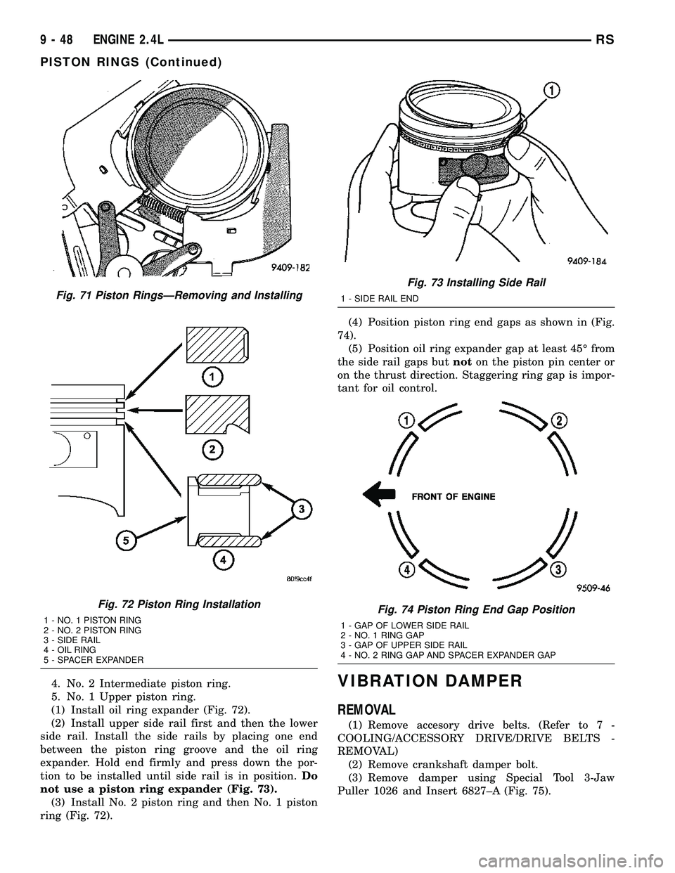
4. No. 2 Intermediate piston ring.
5. No. 1 Upper piston ring.
(1) Install oil ring expander (Fig. 72).
(2) Install upper side rail first and then the lower
side rail. Install the side rails by placing one end
between the piston ring groove and the oil ring
expander. Hold end firmly and press down the por-
tion to be installed until side rail is in position.Do
not use a piston ring expander (Fig. 73).
(3) Install No. 2 piston ring and then No. 1 piston
ring (Fig. 72).(4) Position piston ring end gaps as shown in (Fig.
74).
(5) Position oil ring expander gap at least 45É from
the side rail gaps butnoton the piston pin center or
on the thrust direction. Staggering ring gap is impor-
tant for oil control.VIBRATION DAMPER
REMOVAL
(1) Remove accesory drive belts. (Refer to 7 -
COOLING/ACCESSORY DRIVE/DRIVE BELTS -
REMOVAL)
(2) Remove crankshaft damper bolt.
(3) Remove damper using Special Tool 3-Jaw
Puller 1026 and Insert 6827±A (Fig. 75).
Fig. 71 Piston RingsÐRemoving and Installing
Fig. 72 Piston Ring Installation
1 - NO. 1 PISTON RING
2 - NO. 2 PISTON RING
3 - SIDE RAIL
4 - OIL RING
5 - SPACER EXPANDER
Fig. 73 Installing Side Rail
1 - SIDE RAIL END
Fig. 74 Piston Ring End Gap Position
1 - GAP OF LOWER SIDE RAIL
2 - NO. 1 RING GAP
3 - GAP OF UPPER SIDE RAIL
4 - NO. 2 RING GAP AND SPACER EXPANDER GAP
9 - 48 ENGINE 2.4LRS
PISTON RINGS (Continued)
Page 1226 of 2339
INSTALLATION
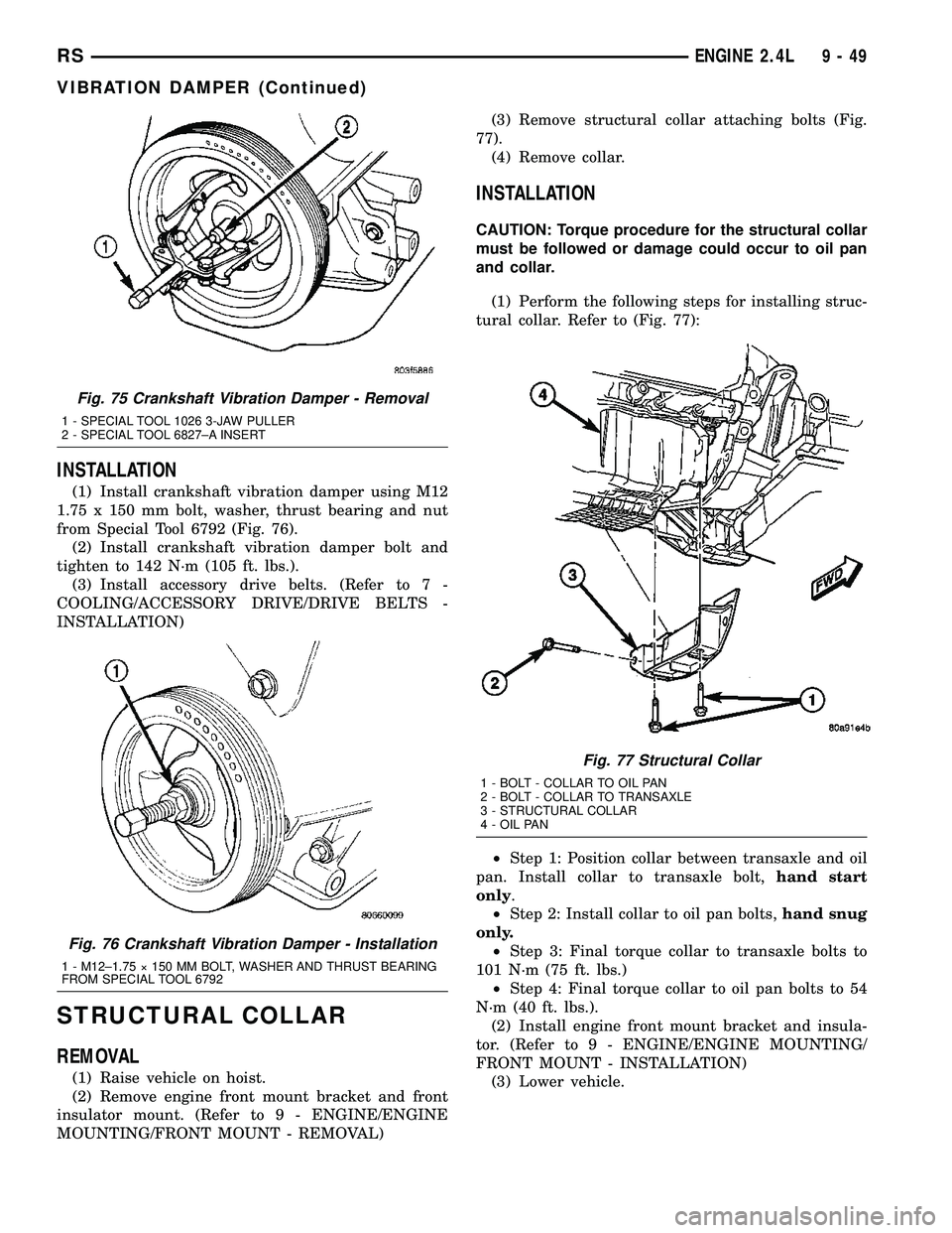
(1) Install crankshaft vibration damper using M12
1.75 x 150 mm bolt, washer, thrust bearing and nut
from Special Tool 6792 (Fig. 76).
(2) Install crankshaft vibration damper bolt and
tighten to 142 N´m (105 ft. lbs.).
(3) Install accessory drive belts. (Refer to 7 -
COOLING/ACCESSORY DRIVE/DRIVE BELTS -
INSTALLATION)
STRUCTURAL COLLAR
REMOVAL
(1) Raise vehicle on hoist.
(2) Remove engine front mount bracket and front
insulator mount. (Refer to 9 - ENGINE/ENGINE
MOUNTING/FRONT MOUNT - REMOVAL)(3) Remove structural collar attaching bolts (Fig.
77).
(4) Remove collar.
INSTALLATION
CAUTION: Torque procedure for the structural collar
must be followed or damage could occur to oil pan
and collar.
(1) Perform the following steps for installing struc-
tural collar. Refer to (Fig. 77):
²Step 1: Position collar between transaxle and oil
pan. Install collar to transaxle bolt,hand start
only.
²Step 2: Install collar to oil pan bolts,hand snug
only.
²Step 3: Final torque collar to transaxle bolts to
101 N´m (75 ft. lbs.)
²Step 4: Final torque collar to oil pan bolts to 54
N´m (40 ft. lbs.).
(2) Install engine front mount bracket and insula-
tor. (Refer to 9 - ENGINE/ENGINE MOUNTING/
FRONT MOUNT - INSTALLATION)
(3) Lower vehicle.
Fig. 75 Crankshaft Vibration Damper - Removal
1 - SPECIAL TOOL 1026 3-JAW PULLER
2 - SPECIAL TOOL 6827±A INSERT
Fig. 76 Crankshaft Vibration Damper - Installation
1 - M12±1.75 ý 150 MM BOLT, WASHER AND THRUST BEARING
FROM SPECIAL TOOL 6792
Fig. 77 Structural Collar
1 - BOLT - COLLAR TO OIL PAN
2 - BOLT - COLLAR TO TRANSAXLE
3 - STRUCTURAL COLLAR
4 - OIL PAN
RSENGINE 2.4L9-49
VIBRATION DAMPER (Continued)
Page 1239 of 2339
INTAKE MANIFOLD - LOWER
REMOVAL
(1) Perform fuel system pressure release proce-
durebefore attempting any repairs.(Refer to 14 -
FUEL SYSTEM/FUEL DELIVERY - STANDARD
PROCEDURE)
(2) Remove upper intake manifold. (Refer to 9 -
ENGINE/MANIFOLDS/INTAKE MANIFOLD -
REMOVAL)
CAUTION: Cover intake manifold openings to pre-
vent foreign material from entering engine.
(3) Disconnect fuel line. (Refer to 14 - FUEL SYS-
TEM/FUEL DELIVERY/QUICK CONNECT FIT-
TING - STANDARD PROCEDURE)
(4) Drain the cooling system. (Refer to 7 - COOL-
ING - STANDARD PROCEDURE)
(5) Remove heater supply and radiator upper
hoses at intake manifold.
(6) Disconnect coolant temperature sensor/fuel
injector wire harness connector.
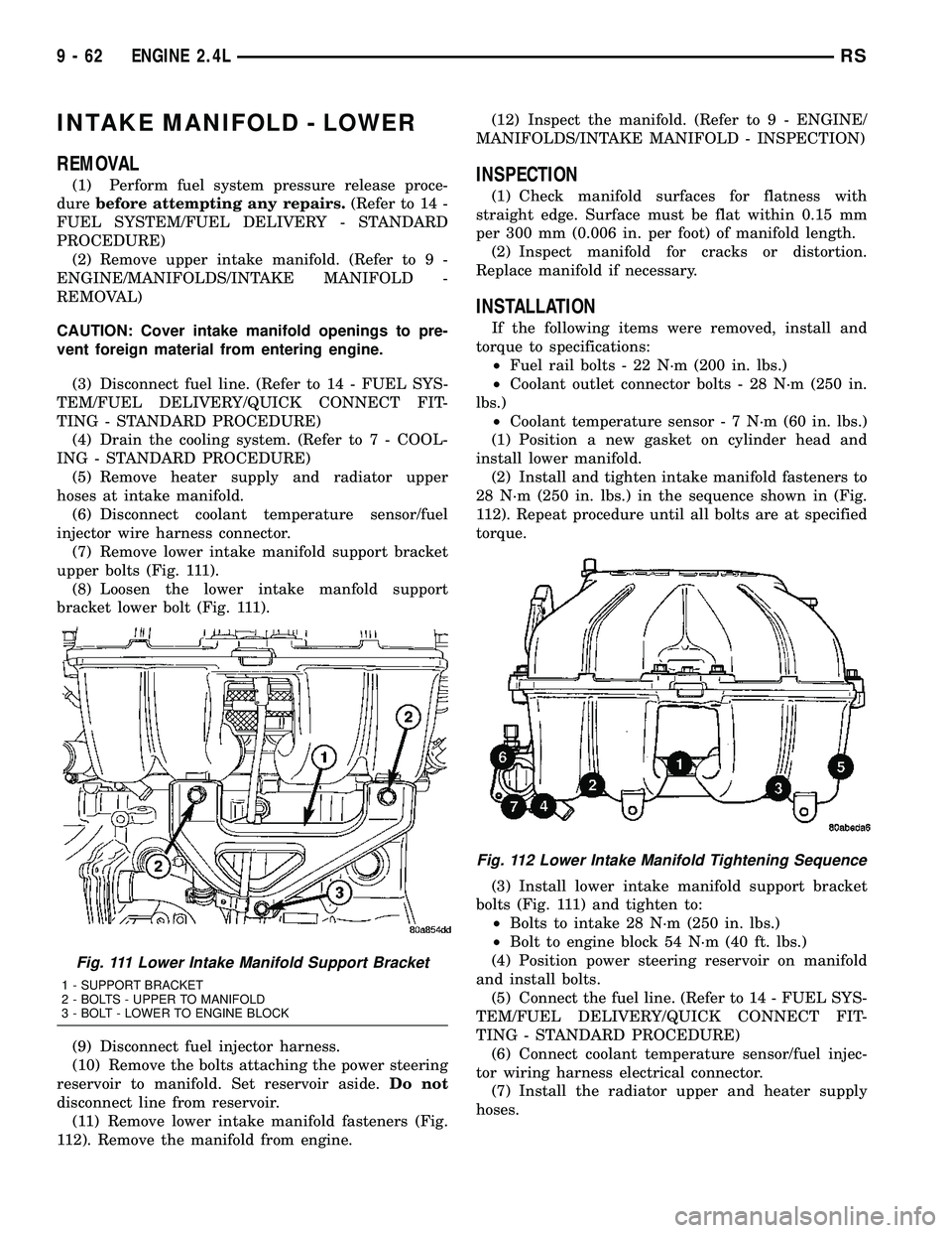
(7) Remove lower intake manifold support bracket
upper bolts (Fig. 111).
(8) Loosen the lower intake manfold support
bracket lower bolt (Fig. 111).
(9) Disconnect fuel injector harness.
(10) Remove the bolts attaching the power steering
reservoir to manifold. Set reservoir aside.Do not
disconnect line from reservoir.
(11) Remove lower intake manifold fasteners (Fig.
112). Remove the manifold from engine.(12) Inspect the manifold. (Refer to 9 - ENGINE/
MANIFOLDS/INTAKE MANIFOLD - INSPECTION)INSPECTION
(1) Check manifold surfaces for flatness with
straight edge. Surface must be flat within 0.15 mm
per 300 mm (0.006 in. per foot) of manifold length.
(2) Inspect manifold for cracks or distortion.
Replace manifold if necessary.
INSTALLATION
If the following items were removed, install and
torque to specifications:
²Fuel rail bolts - 22 N´m (200 in. lbs.)
²Coolant outlet connector bolts - 28 N´m (250 in.
lbs.)
²Coolant temperature sensor - 7 N´m (60 in. lbs.)
(1) Position a new gasket on cylinder head and
install lower manifold.
(2) Install and tighten intake manifold fasteners to
28 N´m (250 in. lbs.) in the sequence shown in (Fig.
112). Repeat procedure until all bolts are at specified
torque.
(3) Install lower intake manifold support bracket
bolts (Fig. 111) and tighten to:
²Bolts to intake 28 N´m (250 in. lbs.)
²Bolt to engine block 54 N´m (40 ft. lbs.)
(4) Position power steering reservoir on manifold
and install bolts.
(5) Connect the fuel line. (Refer to 14 - FUEL SYS-
TEM/FUEL DELIVERY/QUICK CONNECT FIT-
TING - STANDARD PROCEDURE)
(6) Connect coolant temperature sensor/fuel injec-
tor wiring harness electrical connector.
(7) Install the radiator upper and heater supply
hoses.
Fig. 111 Lower Intake Manifold Support Bracket
1 - SUPPORT BRACKET
2 - BOLTS - UPPER TO MANIFOLD
3 - BOLT - LOWER TO ENGINE BLOCK
Fig. 112 Lower Intake Manifold Tightening Sequence
9 - 62 ENGINE 2.4LRS
Page 1240 of 2339
(8) Install the upper intake manifold. (Refer to 9 -
ENGINE/MANIFOLDS/INTAKE MANIFOLD -
INSTALLATION)
(9) Fill the cooling system. (Refer to 7 - COOLING
- STANDARD PROCEDURE)
EXHAUST MANIFOLD
REMOVAL
(1) Raise vehicle and disconnect exhaust pipe from
the exhaust manifold.
(2) Disconnect upstream oxygen sensor connector
at the rear of exhaust manifold.
(3) Remove the bolts attaching the manifold to the
cylinder head.
(4) Remove exhaust manifold.
(5) Inspect the manifold. (Refer to 9 - ENGINE/
MANIFOLDS/EXHAUST MANIFOLD - INSPEC-
TION)
CLEANING
(1) Discard gasket (if equipped) and clean all sur-
faces of manifold and cylinder head.
INSPECTION
(1) Inspect manifold gasket surfaces for flatness
with straight edge. Surface must be flat within 0.15
mm per 300 mm (0.006 in. per foot) of manifold
length.
(2) Inspect manifolds for cracks or distortion.
Replace manifold as necessary.
INSTALLATION
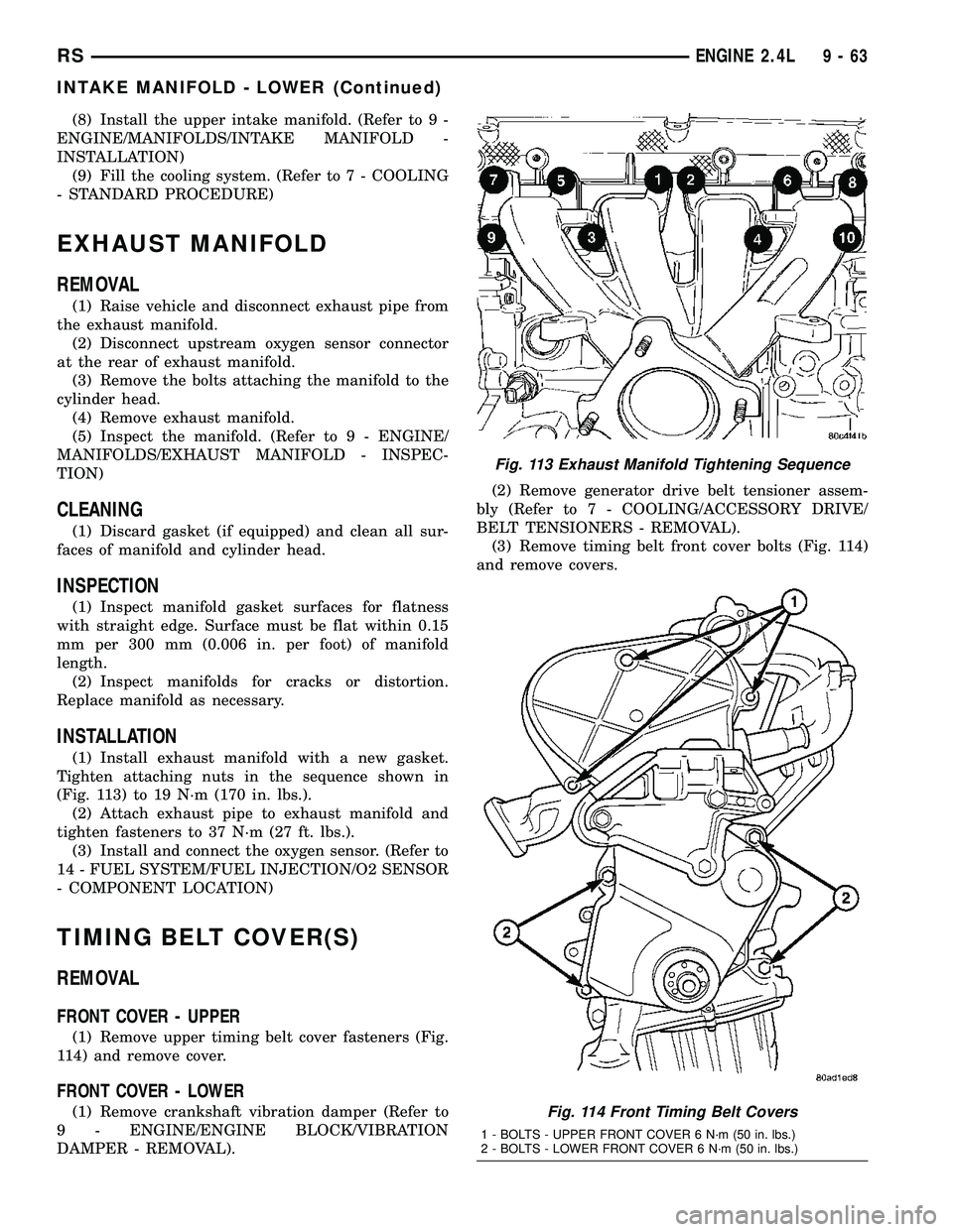
(1) Install exhaust manifold with a new gasket.
Tighten attaching nuts in the sequence shown in
(Fig. 113) to 19 N´m (170 in. lbs.).
(2) Attach exhaust pipe to exhaust manifold and
tighten fasteners to 37 N´m (27 ft. lbs.).
(3) Install and connect the oxygen sensor. (Refer to
14 - FUEL SYSTEM/FUEL INJECTION/O2 SENSOR
- COMPONENT LOCATION)
TIMING BELT COVER(S)
REMOVAL
FRONT COVER - UPPER
(1) Remove upper timing belt cover fasteners (Fig.
114) and remove cover.
FRONT COVER - LOWER
(1) Remove crankshaft vibration damper (Refer to
9 - ENGINE/ENGINE BLOCK/VIBRATION
DAMPER - REMOVAL).(2) Remove generator drive belt tensioner assem-
bly (Refer to 7 - COOLING/ACCESSORY DRIVE/
BELT TENSIONERS - REMOVAL).
(3) Remove timing belt front cover bolts (Fig. 114)
and remove covers.
Fig. 113 Exhaust Manifold Tightening Sequence
Fig. 114 Front Timing Belt Covers
1 - BOLTS - UPPER FRONT COVER 6 N´m (50 in. lbs.)
2 - BOLTS - LOWER FRONT COVER 6 N´m (50 in. lbs.)
RSENGINE 2.4L9-63
INTAKE MANIFOLD - LOWER (Continued)