2005 CHRYSLER CARAVAN battery
[x] Cancel search: batteryPage 2275 of 2339
The following is a list of the monitored compo-
nents:
²Catalyst Monitor
²Comprehensive Components
²EGR (if equipped)
²Fuel Control (rich/lean)
²Oxygen Sensor Monitor
²Oxygen Sensor Heater Monitor
²Purge
²Misfire
²Natural Vacuum Leak Detection (NVLD)
COMPREHENSIVE COMPONENTS
Along with the major monitors, OBD II requires
that the diagnostic system monitor any component
that could affect emissions levels. In many cases,
these components were being tested under OBD I.
The OBD I requirements focused mainly on testing
emissions-related components for electrical opens and
shorts.
However, OBD II also requires that inputs from
powertrain components to the PCM be tested for
rationality, and that outputs to powertrain compo-
nents from the PCM be tested forfunctionality.
Methods for monitoring the various Comprehensive
Component monitoring include:
(1) Circuit Continuity
²Open
²Shorted high
²Shorted to ground
(2) Rationality or Proper Functioning
²Inputs tested for rationality
²Outputs tested for functionality
NOTE: Comprehensive component monitors are
continuous. Therefore, enabling conditions do not
apply. All will set a DTC and illuminate the MIL in 1-
trip.
Input RationalityÐWhile input signals to the
PCM are constantly being monitored for electrical
opens and shorts, they are also tested for rationality.
This means that the input signal is compared against
other inputs and information to see if it makes sense
under the current conditions.
PCM sensor inputs that are checked for rationality
include:
²Manifold Absolute Pressure (MAP) Sensor
²Oxygen Sensor (O2S) (slow response)
²Engine Coolant Temperature (ECT) Sensor
²Camshaft Position (CMP) Sensor
²Vehicle Speed Sensor
²Crankshaft Position (CKP) Sensor
²Intake Air Temperature (IAT) Sensor
²Throttle Position (TPS) Sensor
²Ambient/Battery Temperature Sensors
²Power Steering Switch²Oxygen Sensor Heater
²Engine Controller
²Brake Switch
²Natural Vacuum Leak Detection (NVLD)
²P/N Switch
²Trans Controls
Output FunctionalityÐPCM outputs are tested
for functionality in addition to testing for opens and
shorts. When the PCM provides a voltage to an out-
put component, it can verify that the command was
carried out by monitoring specific input signals for
expected changes. For example, when the PCM com-
mands the Idle Air Control (IAC) Motor to a specific
position under certain operating conditions, it expects
to see a specific (target) idle speed (RPM). If it does
not, it stores a DTC.
PCM outputs monitored for functionality include:
²Fuel Injectors
²Ignition Coils
²Torque Converter Clutch Solenoid
²Idle Air Control
²Purge Solenoid
²EGR Solenoid
²Radiator Fan Control
²Trans Controls
OXYGEN SENSOR (O2S) MONITOR
DESCRIPTIONÐEffective control of exhaust
emissions is achieved by an oxygen feedback system.
The most important element of the feedback system
is the O2S. The O2S is located in the exhaust path.
Once it reaches operating temperature 300É to 350ÉC
(572É to 662ÉF), the sensor generates a voltage that
is inversely proportional to the amount of oxygen in
the exhaust. When there is a large amount of oxygen
in the exhaust caused by a lean condition, misfire or
exhaust leak, the sensor produces a low voltage,
below 450 mV. When the oxygen content is lower,
caused by a rich condition, the sensor produces a
higher voltage, above 450mV.
The information obtained by the sensor is used to
calculate the fuel injector pulse width. The PCM is
programmed to maintain the optimum air/fuel ratio.
At this mixture ratio, the catalyst works best to
remove hydrocarbons (HC), carbon monoxide (CO)
and nitrous oxide (NOx) from the exhaust.
The O2S is also the main sensing element for the
EGR, Catalyst and Fuel Monitors, and purge.
The O2S may fail in any or all of the following
manners:
²Slow response rate (Big Slope)
²Reduced output voltage (Half Cycle)
²Heater Performance
Slow Response Rate (Big Slope)ÐResponse rate
is the time required for the sensor to switch from
lean to rich signal output once it is exposed to a
25 - 2 EMISSIONS CONTROLRS
EMISSIONS CONTROL (Continued)
Page 2276 of 2339
richer than optimum A/F mixture or vice versa. As
the PCM adjusts the air/fuel ratio, the sensor must
be able to rapidly detect the change. As the sensor
ages, it could take longer to detect the changes in the
oxygen content of the exhaust gas. The rate of
change that an oxygen sensor experiences is called
'Big Slope'. The PCM checks the oxygen sensor volt-
age in increments of a few milliseconds.
Reduced Output Voltage (Half Cycle)ÐThe
output voltage of the O2S ranges from 0 to 1 volt. A
good sensor can easily generate any output voltage in
this range as it is exposed to different concentrations
of oxygen. To detect a shift in the A/F mixture (lean
or rich), the output voltage has to change beyond a
threshold value. A malfunctioning sensor could have
difficulty changing beyond the threshold value. Many
times the condition is only temporey and the sensor
will recover. Under normal conditions the voltage sig-
nal surpasses the threshold, and a counter is incre-
mented by one. This is called the Half Cycle Counter.
Heater PerformanceÐThe heater is tested by a
separate monitor. Refer to the Oxygen Sensor Heater
Monitor.
OPERATIONÐAs the Oxygen Sensor signal
switches, the PCM monitors the half cycle and big
slope signals from the oxygen sensor. If during the
test neither counter reaches a predetermined value, a
malfunction is entered and a Freeze Frame is stored.
Only one counter reaching its predetermined value is
needed for the monitor to pass.
The Oxygen Sensor Signal Monitor is a two trip
monitor that is tested only once per trip. When the
Oxygen Sensor fails the test in two consecutive trips,
the MIL is illuminated and a DTC is set. The MIL is
extinguished when the Oxygen Sensor monitor
passes in three consecutive trips. The DTC is erased
from memory after 40 consecutive warm-up cycles
without test failure.
Enabling ConditionsÐThe following conditions
must typically be met for the PCM to run the oxygen
sensor monitor:
²Battery voltage
²Engine temperature
²Engine run time
²Engine run time at a predetermined speed
²Engine run time at a predetermined speed and
throttle opening
²Transmission in gear (automatic only)
²Fuel system in Closed Loop
²Long Term Adaptive (within parameters)
²Power Steering Switch in low PSI (no load)
²Engine at idle
²Fuel level above 15%
²Ambient air temperature
²Barometric pressure²Engine RPM within acceptable range of desired
idle
²Closed throttle speed
Pending ConditionsÐThe Task Manager typi-
cally does not run the Oxygen Sensor Signal Monitor
if overlapping monitors are running or the MIL is
illuminated for any of the following:
²Misfire Monitor
²Front Oxygen Sensor and Heater Monitor
²MAP Sensor
²Vehicle Speed Sensor
²Engine Coolant Temperature Sensor
²Throttle Position Sensor
²Engine Controller Self Test Faults
²Cam or Crank Sensor
²Injector and Coil
²Idle Air Control Motor
²EVAP Electrical
²EGR Solenoid Electrical
²Intake Air Temperature
²5 Volt Feed
ConflictÐThe Task Manager does not run the
Oxygen Sensor Monitor if any of the following condi-
tions are present:
²A/C ON (A/C clutch cycling temporarily sus-
pends monitor)
²Purge flow in progress
²Ethenal content learn is taking place and the
ethenal used once flag is set
SuspendÐThe Task Manager suspends maturing
a fault for the Oxygen Sensor Monitor if an of the fol-
lowing are present:
²Oxygen Sensor Heater Monitor, Priority 1
²Misfire Monitor, Priority 2
OXYGEN SENSOR HEATER MONITOR (NGC)
DESCRIPTIONÐIf the Oxygen sensor (O2S) DTC
as well as a O2S heater DTC is present, the O2S
Heater DTC MUST be repaired first. After the O2S
Heater is repaired, verify that the sensor circuit is
operating correctly.
The voltage reading taken from the O2S are very
temperature sensitive. The readings taken from the
O2S are not accurate below 300 degrees C. Heating
the O2S is done to allow the engine controller to shift
to closed loop control as soon as possible. The heating
element used to heat the O2S must be tested to
ensure that it is heating the sensor properly. Starting
with the introduction on the NGC module the strat-
egy for checking the heater circuit has changed. The
heater resistance is checked by the NGC almost
immediately after the engine is started. The same
O2S heater return pin used to read the heater resis-
tance is capable of detecting an open circuit, a
shorted high or shorted low condition.
RSEMISSIONS CONTROL25-3
EMISSIONS CONTROL (Continued)
Page 2277 of 2339
OXYGEN SENSOR HEATER MONITOR (SBEC)
DESCRIPTIONÐIf there is an oxygen sensor
(O2S) DTC as well as a O2S heater DTC, the O2S
heater fault MUST be repaired first. After the O2S
fault is repaired, verify that the heater circuit is
operating correctly.
The voltage readings taken from the O2S are very
temperature sensitive. The readings are not accurate
below 300ÉC. Heating of the O2S is done to allow the
engine controller to shift to closed loop control as
soon as possible. The heating element used to heat
the O2S must be tested to ensure that it is heating
the sensor properly.
The heater element itself is not tested directly. The
sensor output is used to test the heater by isolating
the effect of the heater element on the O2S output
voltage from the other effects. The resistance is nor-
mally between 100 ohms and 4.5 megaohms. When
oxygen sensor temperature increases, the resistance
in the internal circuit decreases. The PCM sends a 5
volts biased signal through the oxygen sensors to
ground this monitoring circuit. As the temperature
increases, resistance decreases and the PCM detects
a lower voltage at the reference signal. Inversely, as
the temperature decreases, the resistance increases
and the PCM detects a higher voltage at the refer-
ence signal. The O2S circuit is monitored for a drop
in voltage.
OPERATIONÐThe Oxygen Sensor Heater Moni-
tor begins after the ignition has been turned OFF
and the O2 sensors have cooled. The PCM sends a 5
volt bias to the oxygen sensor every 1.6 seconds. The
PCM keeps it biased for 35 ms each time. As the sen-
sor cools down, the resistance increases and the PCM
reads the increase in voltage. Once voltage has
increased to a predetermined amount, higher than
when the test started, the oxygen sensor is cool
enough to test heater operation.
When the oxygen sensor is cool enough, the PCM
energizes the ASD relay. Voltage to the O2 sensor
begins to increase the temperature. As the sensor
temperature increases, the internal resistance
decreases. The PCM continues biasing the 5 volt sig-
nal to the sensor. Each time the signal is biased, the
PCM reads a voltage decrease. When the PCM
detects a voltage decrease of a predetermined value
for several biased pulses, the test passes.
The heater elements are tested each time the
engine is turned OFF if all the enabling conditions
are met. If the monitor fails, the PCM stores a
maturing fault and a Freeze Frame is entered. If two
consecutive tests fail, a DTC is stored. Because the
ignition is OFF, the MIL is illuminated at the begin-
ning of the next key cycle, after the 2nd failure.Enabling ConditionsÐThe following conditions
must be met for the PCM to run the oxygen sensor
heater test:
²Engine run time of at least 5.1 minutes
²Key OFF power down
²Battery voltage of at least 10 volts
²Sufficient Oxygen Sensor cool down
Pending ConditionsÐThere are not conditions or
situations that prompt conflict or suspension of test-
ing. The oxygen sensor heater test is not run pending
resolution of MIL illumination due to oxygen sensor
failure.
SuspendÐThere are no conditions which exist for
suspending the Heater Monitor.
CATALYST MONITOR
To comply with clean air regulations, vehicles are
equipped with catalytic converters. These converters
reduce the emission of hydrocarbons, oxides of nitro-
gen and carbon monoxide.
Normal vehicle miles or engine misfire can cause a
catalyst to decay. A meltdown of the ceramic core can
cause a reduction of the exhaust passage. This can
increase vehicle emissions and deteriorate engine
performance, driveability and fuel economy.
The catalyst monitor uses dual oxygen sensors
(O2S's) to monitor the efficiency of the converter. The
dual O2S strategy is based on the fact that as a cat-
alyst deteriorates, its oxygen storage capacity and its
efficiency are both reduced. By monitoring the oxy-
gen storage capacity of a catalyst, its efficiency can
be indirectly calculated. The upstream O2S is used to
detect the amount of oxygen in the exhaust gas
before the gas enters the catalytic converter. The
PCM calculates the A/F mixture from the output of
the O2S. A low voltage indicates high oxygen content
(lean mixture). A high voltage indicates a low content
of oxygen (rich mixture).
When the upstream O2S detects a high oxygen
condition, there is an abundance of oxygen in the
exhaust gas. A functioning converter would store this
oxygen so it can use it for the oxidation of HC and
CO. As the converter absorbs the oxygen, there will
be a lack of oxygen downstream of the converter. The
output of the downstream O2S will indicate limited
activity in this condition.
As the converter loses the ability to store oxygen,
the condition can be detected from the behavior of
the downstream O2S. When the efficiency drops, no
chemical reaction takes place. This means the con-
centration of oxygen will be the same downstream as
upstream. The output voltage of the downstream
O2S copies the voltage of the upstream sensor. The
only difference is a time lag (seen by the PCM)
between the switching of the O2S's.
25 - 4 EMISSIONS CONTROLRS
EMISSIONS CONTROL (Continued)
Page 2282 of 2339
as well as allowing sufficient purge flow in the event
that the solenoid was to become inoperative.
The solenoid actuates the valve to unseal the can-
ister vent while the engine is running. It also will be
used to close the vent during the medium and large
leak tests and during the purge flow check. This sole-
noid requires initial 1.5 amps of current to pull the
valve open but after 100 ms. will be duty cycled down
to an average of about 150 mA for the remainder of
the drive cycle.
Another feature in the device is a diaphragm that
will open the seal in the NVLD with pressure in the
evaporative system. The device will9blow off9at
about 0.59H2O (0.12 KPA) pressure to permit the
venting of vapors during refueling. An added benefit
to this is that it will also allow the tank to9breathe9
during increasing temperatures, thus limiting the
pressure in the tank to this low level. This is benefi-
cial because the induced vacuum during a subse-
quent declining temperature will achieve the switch
closed (pass threshold) sooner than if the tank had to
decay from a built up pressure.
The device itself has 3 wires: Switch sense, sole-
noid driver and ground. It also includes a resistor to
protect the switch from a short to battery or a short
to ground. The NGC utilizes a high-side driver to
energize and duty-cycle the solenoid.
HIGH AND LOW LIMITS
The PCM compares input signal voltages from each
input device with established high and low limits for
the device. If the input voltage is not within limits
and other criteria are met, the PCM stores a diagnos-
tic trouble code in memory. Other diagnostic trouble
code criteria might include engine RPM limits or
input voltages from other sensors or switches that
must be present before verifying a diagnostic trouble
code condition.
OPERATION
SYSTEM
The Powertrain Control Module (PCM) monitors
many different circuits in the fuel injection, ignition,
emission and engine systems. If the PCM senses a
problem with a monitored circuit often enough to
indicate an actual problem, it stores a Diagnostic
Trouble Code (DTC) in the PCM's memory. If the
code applies to a non-emissions related component or
system, and the problem is repaired or ceases to
exist, the PCM cancels the code after 40 warmup
cycles. Diagnostic trouble codes that affect vehicle
emissions illuminate the Malfunction Indicator Lamp
(MIL). Refer to Malfunction Indicator Lamp in this
section.Certain criteria must be met before the PCM
stores a DTC in memory. The criteria may be a spe-
cific range of engine RPM, engine temperature,
and/or input voltage to the PCM.
The PCM might not store a DTC for a monitored
circuit even though a malfunction has occurred. This
may happen because one of the DTC criteria for the
circuit has not been met.For example, assume the
diagnostic trouble code criteria requires the PCM to
monitor the circuit only when the engine operates
between 750 and 2000 RPM. Suppose the sensor's
output circuit shorts to ground when engine operates
above 2400 RPM (resulting in 0 volt input to the
PCM). Because the condition happens at an engine
speed above the maximum threshold (2000 rpm), the
PCM will not store a DTC.
There are several operating conditions for which
the PCM monitors and sets DTC's. Refer to Moni-
tored Systems, Components, and Non-Monitored Cir-
cuits in this section.
NOTE: Various diagnostic procedures may actually
cause a diagnostic monitor to set a DTC. For
instance, pulling a spark plug wire to perform a
spark test may set the misfire code. When a repair
is completed and verified, use the scan tool to
erase all DTC's and extinguish the MIL.
Technicians can display stored DTC's. For obtain-
ing the DTC information, use the Data Link Connec-
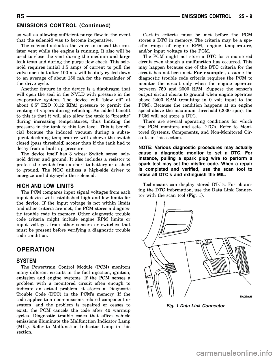
tor with the scan tool (Fig. 1).
Fig. 1 Data Link Connector
RSEMISSIONS CONTROL25-9
EMISSIONS CONTROL (Continued)
Page 2287 of 2339
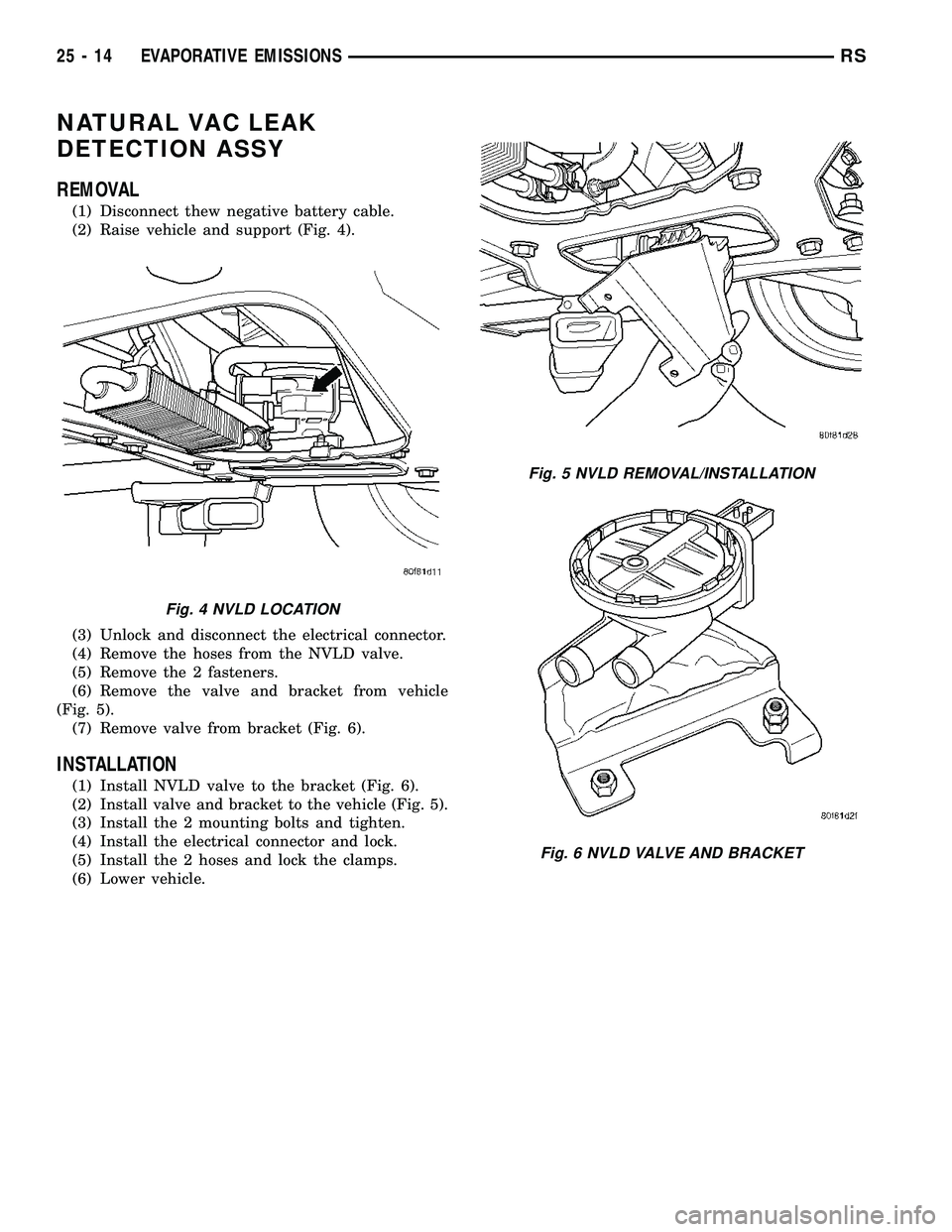
NATURAL VAC LEAK
DETECTION ASSY
REMOVAL
(1) Disconnect thew negative battery cable.
(2) Raise vehicle and support (Fig. 4).
(3) Unlock and disconnect the electrical connector.
(4) Remove the hoses from the NVLD valve.
(5) Remove the 2 fasteners.
(6) Remove the valve and bracket from vehicle
(Fig. 5).
(7) Remove valve from bracket (Fig. 6).
INSTALLATION
(1) Install NVLD valve to the bracket (Fig. 6).
(2) Install valve and bracket to the vehicle (Fig. 5).
(3) Install the 2 mounting bolts and tighten.
(4) Install the electrical connector and lock.
(5) Install the 2 hoses and lock the clamps.
(6) Lower vehicle.
Fig. 4 NVLD LOCATION
Fig. 5 NVLD REMOVAL/INSTALLATION
Fig. 6 NVLD VALVE AND BRACKET
25 - 14 EVAPORATIVE EMISSIONSRS
Page 2288 of 2339
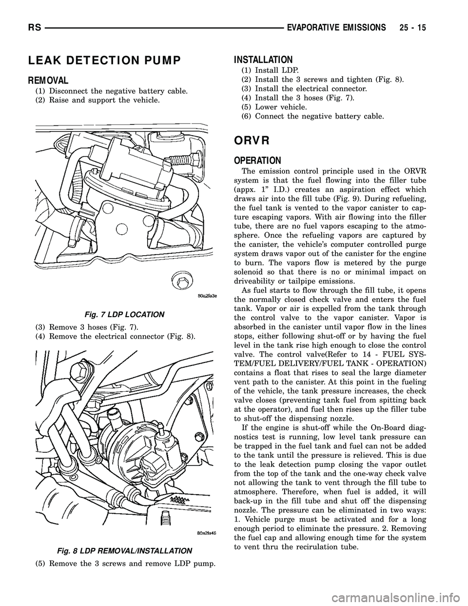
LEAK DETECTION PUMP
REMOVAL
(1) Disconnect the negative battery cable.
(2) Raise and support the vehicle.
(3) Remove 3 hoses (Fig. 7).
(4) Remove the electrical connector (Fig. 8).
(5) Remove the 3 screws and remove LDP pump.
INSTALLATION
(1) Install LDP.
(2) Install the 3 screws and tighten (Fig. 8).
(3) Install the electrical connector.
(4) Install the 3 hoses (Fig. 7).
(5) Lower vehicle.
(6) Connect the negative battery cable.
ORVR
OPERATION
The emission control principle used in the ORVR
system is that the fuel flowing into the filler tube
(appx. 1º I.D.) creates an aspiration effect which
draws air into the fill tube (Fig. 9). During refueling,
the fuel tank is vented to the vapor canister to cap-
ture escaping vapors. With air flowing into the filler
tube, there are no fuel vapors escaping to the atmo-
sphere. Once the refueling vapors are captured by
the canister, the vehicle's computer controlled purge
system draws vapor out of the canister for the engine
to burn. The vapors flow is metered by the purge
solenoid so that there is no or minimal impact on
driveability or tailpipe emissions.
As fuel starts to flow through the fill tube, it opens
the normally closed check valve and enters the fuel
tank. Vapor or air is expelled from the tank through
the control valve to the vapor canister. Vapor is
absorbed in the canister until vapor flow in the lines
stops, either following shut-off or by having the fuel
level in the tank rise high enough to close the control
valve. The control valve(Refer to 14 - FUEL SYS-
TEM/FUEL DELIVERY/FUEL TANK - OPERATION)
contains a float that rises to seal the large diameter
vent path to the canister. At this point in the fueling
of the vehicle, the tank pressure increases, the check
valve closes (preventing tank fuel from spitting back
at the operator), and fuel then rises up the filler tube
to shut-off the dispensing nozzle.
If the engine is shut-off while the On-Board diag-
nostics test is running, low level tank pressure can
be trapped in the fuel tank and fuel can not be added
to the tank until the pressure is relieved. This is due
to the leak detection pump closing the vapor outlet
from the top of the tank and the one-way check valve
not allowing the tank to vent through the fill tube to
atmosphere. Therefore, when fuel is added, it will
back-up in the fill tube and shut off the dispensing
nozzle. The pressure can be eliminated in two ways:
1. Vehicle purge must be activated and for a long
enough period to eliminate the pressure. 2. Removing
the fuel cap and allowing enough time for the system
to vent thru the recirulation tube.
Fig. 7 LDP LOCATION
Fig. 8 LDP REMOVAL/INSTALLATION
RSEVAPORATIVE EMISSIONS25-15
Page 2300 of 2339
Alternate Good Trip
Alternate Good Trips are used in place of Global
Good Trips for Comprehensive Components and
Major Monitors. If the Task Manager cannot run a
Global Good Trip because a component fault is stop-
ping the monitor from running, it will attempt to
count an Alternate Good Trip.
The Task Manager counts an Alternate Good Trip
for Comprehensive components when the following
conditions are met:
²Two minutes of engine run time, idle or driving
²No other faults occur
The Task Manager counts an Alternate Good Trip
for a Major Monitor when the monitor runs and
passes. Only the Major Monitor that failed needs to
pass to count an Alternate Good Trip.
Warm-Up Cycles
Once the MIL has been extinguished by the Good
Trip Counter, the PCM automatically switches to a
Warm-Up Cycle Counter that can be viewed on the
scan tool. Warm-Up Cycles are used to erase DTCs
and Freeze Frames. Forty Warm-Up cycles must
occur in order for the PCM to self-erase a DTC and
Freeze Frame. A Warm-Up Cycle is defined as fol-
lows:
²Engine coolant temperature must start below
and rise above 160É F
²Engine coolant temperature must rise by 40É F
²No further faults occur
Freeze Frame Data Storage
Once a failure occurs, the Task Manager records
several engine operating conditions and stores it in a
Freeze Frame. The Freeze Frame is considered one
frame of information taken by an on-board data
recorder. When a fault occurs, the PCM stores the
input data from various sensors so that technicians
can determine under what vehicle operating condi-
tions the failure occurred.
The data stored in Freeze Frame is usually
recorded when a system fails the first time for two
trip faults. Freeze Frame data will only be overwrit-
ten by a different fault with a higher priority.
CAUTION: Erasing DTCs, either with the scan tool;
or by disconnecting the battery, also clears all
Freeze Frame data.
Similar Conditions Window
The Similar Conditions Window displays informa-
tion about engine operation during a monitor. Abso-
lute MAP (engine load) and Engine RPM are stored
in this window when a failure occurs. There are two
different Similar conditions Windows: Fuel System
and Misfire.FUEL SYSTEM
²Fuel System Similar Conditions WindowÐ
An indicator that 'Absolute MAP When Fuel Sys Fail'
and 'RPM When Fuel Sys Failed' are all in the same
range when the failure occurred. Indicated by switch-
ing from 'NO' to 'YES'.
²Absolute MAP When Fuel Sys FailÐ The
stored MAP reading at the time of failure. Informs
the user at what engine load the failure occurred.
²Absolute MAPÐ A live reading of engine load
to aid the user in accessing the Similar Conditions
Window.
²RPM When Fuel Sys FailÐ The stored RPM
reading at the time of failure. Informs the user at
what engine RPM the failure occurred.
²Engine RPMÐ A live reading of engine RPM
to aid the user in accessing the Similar Conditions
Window.
²Adaptive Memory FactorÐ The PCM utilizes
both Short Term Compensation and Long Term Adap-
tive to calculate the Adaptive Memory Factor for
total fuel correction.
²Upstream O2S VoltsÐ A live reading of the
Oxygen Sensor to indicate its performance. For
example, stuck lean, stuck rich, etc.
²SCW Time in Window (Similar Conditions
Window Time in Window)Ð A timer used by the
PCM that indicates that, after all Similar Conditions
have been met, if there has been enough good engine
running time in the SCW without failure detected.
This timer is used to increment a Good Trip.
²Fuel System Good Trip CounterÐATrip
Counter used to turn OFF the MIL for Fuel System
DTCs. To increment a Fuel System Good Trip, the
engine must be in the Similar Conditions Window,
Adaptive Memory Factor must be less than cali-
brated threshold and the Adaptive Memory Factor
must stay below that threshold for a calibrated
amount of time.
²Test Done This TripÐ Indicates that the
monitor has already been run and completed during
the current trip.
MISFIRE
²Same Misfire Warm-Up StateÐ Indicates if
the misfire occurred when the engine was warmed up
(above 160É F).
²In Similar Misfire WindowÐ An indicator
that 'Absolute MAP When Misfire Occurred' and
'RPM When Misfire Occurred' are all in the same
range when the failure occurred. Indicated by switch-
ing from 'NO' to 'YES'.
²Absolute MAP When Misfire OccurredÐ
The stored MAP reading at the time of failure.
Informs the user at what engine load the failure
occurred.
RSON-BOARD DIAGNOSTICS25-27
TASK MANAGER (Continued)
Page 2304 of 2339
BACKLIGHT (EBL) SYSTEM, DIAGNOSISAND TESTING - ELECTRIC ..............8G-2
BACKSTOW STRAP - THIRD ROW - FOLD-IN-FLOOR - INSTALLATION, SEAT . . 23-158
BACKSTOW STRAP - THIRD ROW - FOLD-IN-FLOOR - REMOVAL, SEAT ......23-158
BAG RETAINER - INSTALLATION, PLASTIC GROCERY .................. 23-149
BAG RETAINER - REMOVAL, PLASTIC GROCERY ......................... 23-149
BALANCE - STANDARD PROCEDURE, TIRE AND WHEEL ..................... 22-5
BALANCE SHAFTS AND CARRIER ASSEMBLY - DESCRIPTION .............9-71
BALANCE SHAFTS AND CARRIER ASSEMBLY - INSTALLATION .............9-73
BALANCE SHAFTS AND CARRIER ASSEMBLY - OPERATION ...............9-71
BALANCE SHAFTS AND CARRIER ASSEMBLY - REMOVAL .................9-71
BALL JOINT - DESCRIPTION, LOWER ......2-10
BALL JOINT - DIAGNOSIS AND TESTING, LOWER ............................. 2-10
BALL JOINT - OPERATION, LOWER .......2-10
BAR - DESCRIPTION, STABILIZER ....2-16,2-44
BAR - DESCRIPTION, TRACK ............2-45
BAR - INSPECTION, STABILIZER ..........2-17
BAR - INSTALLATION, STABILIZER ........2-17
BAR - INSTALLATION, TRACK ............2-46
BAR - OPERATION, STABILIZER ......2-16,2-44
BAR - OPERATION, TRACK ................2-46
BAR - REMOVAL, STABILIZER ...........2-17
BAR - REMOVAL, TRACK ...............2-46
BAR CUSHION - INSTALLATION, STABILIZER ...........................2-4
BAR CUSHION - REMOVAL, STABILIZER ....2-4
BASE BRAKE BLEEDING - STANDARD PROCEDURE ..........................5-8
BASE BRAKE SYSTEM - DIAGNOSIS AND TESTING .............................5-4
BASE BRAKE SYSTEM, SPECIAL TOOLS ....5-10
BASE BRAKES - DESCRIPTION ............5-3
BASE BRAKES - OPERATION ..............5-3
BASE BRAKES (EXPORT) - DESCRIPTION . . . 5-3
BASE COAT/CLEARCOAT FINISH - DESCRIPTION ...................... 23-101
BASE RISER - SECOND ROW - FOLD-IN-FLOOR - INSTALLATION, SEAT . . 23-135
BASE RISER - SECOND ROW - FOLD-IN-FLOOR - REMOVAL, SEAT ......23-134
BASE TRAY - INSTALLATION, FLOOR CONSOLE ........................... 23-89
BASE TRAY - REMOVAL, FLOOR CONSOLE ........................... 23-89
BATTERY - DESCRIPTION ...............8F-7
BATTERY - OPERATION .................8F-9
BATTERY - REMOVAL .................8F-16
BATTERY - SPECIFICATIONS ............8N-24
BATTERY CABLES - DESCRIPTION .......8F-16
BATTERY CABLES - OPERATION .........8F-17
BATTERY CABLES, DIAGNOSIS AND TESTING ........................... 8F-17
BATTERY CHARGING, STANDARD PROCEDURE - CONVENTIONAL ..........8F-11
BATTERY CHARGING, STANDARD PROCEDURE - SPIRAL PLATE ...........8F-10
BATTERY, DIAGNOSIS AND TESTING ......8F-9
BATTERY ELECTROLYTE LEVEL, STANDARD PROCEDURE - CHECKING ....8F-14
BATTERY HOLDDOWN - INSTALLATION . . . 8F-16
BATTERY HOLDDOWN - REMOVAL .......8F-16
BATTERY REPLACEMENT - STANDARD PROCEDURE ........................ 8N-24
BATTERY, SPECIFICATIONS ..............8F-6
BATTERY SYSTEM - DESCRIPTION ........8F-1
BATTERY SYSTEM - OPERATION .........8F-2
BATTERY SYSTEM, DIAGNOSIS AND TESTING ............................ 8F-2
BATTERY SYSTEM SPECIAL TOOLS, SPECIAL TOOLS ...................... 8F-7
BATTERY TEMPERATURE SENSOR - DESCRIPTION ....................... 8F-24
BATTERY TEMPERATURE SENSOR - OPERATION ......................... 8F-24
BATTERY TEMPERATURE SENSOR - REMOVAL .......................... 8F-24
BATTERY TEMPERATURE SENSOR - SPECIFICATIONS ..................... 8F-23BATTERY TESTER, STANDARD
PROCEDURE - MICRO 420 .............8F-15
BATTERY TRAY - DESCRIPTION .........8F-19
BATTERY TRAY - INSTALLATION .........8F-20
BATTERY TRAY - REMOVAL ............8F-19
BEARING - DESCRIPTION, HUB .......2-30,2-5
BEARING - DIAGNOSIS AND TESTING, HUB............................. 2-31,2-5
BEARING - INSTALLATION, HUB .......2-33,2-5
BEARING - OPERATION, HUB .........2-30,2-5
BEARING - REMOVAL, HUB ..........2-31,2-5
BEARING CLEARANCE - STANDARD PROCEDURE, MEASURING
CONNECTING ROD ................... 9-123
BEARING CLEARANCE USING PLASTIGAGE - STANDARD
PROCEDURE, MEASURING ..........9-12,9-86
BEARING FITTING - STANDARD PROCEDURE, MAIN ................... 9-125
BEARING PRELOAD - ADJUSTMENT, DIFFERENTIAL ...................... 21-228
BEARING PRELOAD MEASUREMENT AND ADJUSTMENT, ADJUSTMENTS -
DIFFERENTIAL ....................... 21-79
BEARINGS - INSTALLATION, CRANKSHAFT MAIN .................. 9-127
BEARINGS - REMOVAL, CRANKSHAFT MAIN .............................. 9-127
BEARINGS (IN BLOCK) - DESCRIPTION, CAMSHAFT ......................... 9-118
BEARINGS (IN BLOCK) - INSPECTION, CAMSHAFT ......................... 9-118
BEARINGS (IN BLOCK) - INSTALLATION, CAMSHAFT ......................... 9-118
BEARINGS (IN BLOCK) - OPERATION, CAMSHAFT ......................... 9-118
BEARINGS (IN BLOCK) - REMOVAL, CAMSHAFT ......................... 9-118
BELLCRANK - INSTALLATION ...........23-35
BELLCRANK - REMOVAL ...............23-35
BELT - DIAGNOSIS AND TESTING, ACCESSORY DRIVE .....................7-7
BELT - FOLD-IN-FLOOR - INSTALLATION, SEAT BELT CENTER LAP ..............23-157
BELT - FOLD-IN-FLOOR - REMOVAL, SEAT BELT CENTER LAP ..............23-157
BELT - INSTALLATION, TIMING ...........9-67
BELT - REMOVAL, TIMING ..............9-65
BELT & RETRACTOR - FIRST ROW - OUTBOARD - INSTALLATION, SEAT ......8O-40
BELT & RETRACTOR - FIRST ROW - OUTBOARD - REMOVAL, SEAT ..........8O-39
BELT & RETRACTOR - OUTBOARD - FRONT - INSTALLATION, SEAT ..........8O-39
BELT & RETRACTOR - OUTBOARD - FRONT - REMOVAL, SEAT ..............8O-38
BELT & RETRACTOR - SECOND ROW - LEFT OUTBOARD - INSTALLATION,
SEAT .............................. 8O-42
BELT & RETRACTOR - SECOND ROW - LEFT OUTBOARD - REMOVAL, SEAT .....8O-42
BELT & RETRACTOR - SECOND ROW - RIGHT OUTBOARD - INSTALLATION,
SEAT .............................. 8O-40
BELT & RETRACTOR - SECOND ROW - RIGHT OUTBOARD - REMOVAL, SEAT ....8O-40
BELT & RETRACTOR - SECOND ROW - RIGHT OUTBOARD WITH REAR HVAC -
LWB - INSTALLATION, SEAT ............8O-41
BELT & RETRACTOR - SECOND ROW - RIGHT OUTBOARD WITH REAR HVAC -
LWB - REMOVAL, SEAT ...............8O-41
BELT BUCKLE - FIRST ROW - BENCH - INSTALLATION, SEAT .................8O-37
BELT BUCKLE - FIRST ROW - BENCH - REMOVAL, SEAT ..................... 8O-36
BELT BUCKLE - FIRST ROW INBOARD - QUAD BUCKET - INSTALLATION, SEAT ....8O-36
BELT BUCKLE - FIRST ROW INBOARD - QUAD BUCKET - REMOVAL, SEAT .......8O-35
BELT BUCKLE - FRONT INBOARD - INSTALLATION, SEAT .................8O-35
BELT BUCKLE - FRONT INBOARD - REMOVAL, SEAT ..................... 8O-35
BELT BUCKLE - SECOND ROW - THREE PASSENGER BENCH - INSTALLATION,
SEAT .............................. 8O-40BELT BUCKLE - SECOND ROW - THREE
PASSENGER BENCH - REMOVAL, SEAT . . . 8O-40
BELT BUCKLE - SECOND ROW INBOARD - 50/50 BENCH - INSTALLATION, SEAT . . . 8O-38
BELT BUCKLE - SECOND ROW INBOARD - 50/50 BENCH - REMOVAL, SEAT .......8O-37
BELT CENTER LAP BELT - FOLD-IN- FLOOR - INSTALLATION, SEAT .........23-157
BELT CENTER LAP BELT - FOLD-IN- FLOOR - REMOVAL, SEAT .............23-157
BELT COVER(S) - INSTALLATION, TIMING ............................. 9-64
BELT COVER(S) - REMOVAL, TIMING ......9-63
BELT HEIGHT ADJUSTE R-BOR
C-PILLAR - INSTALLATION, SEAT ........8O-38
BELT HEIGHT ADJUSTE R-BOR
C-PILLAR - REMOVAL, SEAT ...........8O-38
BELT HEIGHT ADJUSTER KNOB - INSTALLATION, SEAT .................8O-38
BELT HEIGHT ADJUSTER KNOB - REMOVAL, SEAT ..................... 8O-38
BELT MOLDING - INSTALLATION, FRONT DOOR INNER ....................... 23-168
BELT MOLDING - INSTALLATION, FRONT DOOR OUTER ...................... 23-167
BELT MOLDING - REMOVAL, FRONT DOOR INNER ....................... 23-168
BELT MOLDING - REMOVAL, FRONT DOOR OUTER ...................... 23-167
BELT TENSION - STANDARD PROCEDURE, CHECKING POWER
STEERING ............................7-8
BELT TENSION SENSOR - DESCRIPTION . . . 8O-8
BELT TENSION SENSOR - OPERATION .....8O-9
BELT TENSION, SPECIFICATIONS - ACCESSORY DRIVE .....................7-5
BELT TENSIONER - 2.4L - INSTALLATION . . 7-11
BELT TENSIONER - 2.4L - REMOVAL ......7-11
BELT TENSIONER - 3.3/3.8L - INSTALLATION ........................ 7-12
BELT TENSIONER - 3.3/3.8L - REMOVAL . . . 7-12
BELT TENSIONER - DESCRIPTION, SEAT . . 8O-43
BELT TENSIONER - OPERATION, SEAT ....8O-43
BELT TENSIONER & PULLEY - INSTALLATION, TIMING .................9-70
BELT TENSIONER & PULLEY - REMOVAL, TIMING .................... 9-69
BELTS - 2.4L - ADJUSTMENTS, DRIVE .....7-10
BELTS - 2.4L - INSTALLATION, DRIVE ......7-9
BELTS - 2.4L - REMOVAL, DRIVE ..........7-9
BELTS - 3.3/3.8L - INSTALLATION, DRIVE . . 7-12
BELTS - 3.3/3.8L - REMOVAL, DRIVE ......7-11
BELTS - CLEANING, DRIVE ...............7-8
BELTS - INSPECTION, DRIVE .............7-8
BENCH - INSTALLATION, SEAT BACK HINGE COVERS - QUAD BUCKET, 50/50
SPLIT ............................. 23-146
BENCH - INSTALLATION, SEAT BELT BUCKLE - FIRST ROW ................8O-37
BENCH - INSTALLATION, SEAT BELT BUCKLE - SECOND ROW - THREE
PASSENGER ........................ 8O-40
BENCH - INSTALLATION, SEAT BELT BUCKLE - SECOND ROW INBOARD -
50/50 .............................. 8O-38
BENCH - INSTALLATION, SEAT CUSHION COVER - QUAD BUCKET, 50/50 SPLIT . . . 23-144
BENCH - REMOVAL, SEAT BACK HINGE COVERS - QUAD BUCKET, 50/50 SPLIT . . 23-146
BENCH - REMOVAL, SEAT BELT BUCKLE - FIRST ROW ....................... 8O-36
BENCH - REMOVAL, SEAT BELT BUCKLE - SECOND ROW - THREE PASSENGER ....8O-40
BENCH - REMOVAL, SEAT BELT BUCKLE - SECOND ROW INBOARD - 50/50 .......8O-37
BENCH - REMOVAL, SEAT CUSHION COVER - QUAD BUCKET, 50/50 SPLIT . . . 23-144
BENCH SEAT - REMOVAL, CHILD SEAT MODULE .......................... 23-104
BENCH SEAT BACK - INSTALLATION .....23-147
BENCH SEAT BACK - REMOVAL ........23-147
BENCH SEAT BACK COVER - INSTALLATION ...................... 23-148
BENCH SEAT BACK COVER - REMOVAL . . 23-148
BENCH SEAT BACK HINGE - REMOVAL . . 23-146
BENCH SEAT BACK PANEL - INSTALLATION ...................... 23-144
BENCH SEAT BACK PANEL - REMOVAL . . 23-143
RS INDEX3
Description Group-Page Description Group-Page Description Group-Page