2005 CHRYSLER CARAVAN battery
[x] Cancel search: batteryPage 2243 of 2339
(7) Lubricate a new rubber O-ring seal with clean
refrigerant oil and install it on the liquid line fitting.
(8) Reconnect the A/C liquid line to the receiver/
drier.
(9) Install the bolt that secures the A/C liquid line
to the receiver/drier. Tighten the bolt to 11 N´m (97
in. lbs.).
(10) If equipped, reinstall the A/C ground strap
eyelet terminal connector onto the weld stud on the
top of the right front strut tower (if equipped).
(11) If equipped, install the nut that secures the
A/C ground strap to the weld stud. Tighten the nut
to 12 N´m (106 in. lbs.)
(12) Install the A/C pressure transducer (Refer to
24 - HEATING & AIR CONDITIONING/CONTROLS
- FRONT/A/C PRESSURE TRANSDUCER - INSTAL-
LATION).
(13) Connect the drain tube to the wiper module
drain on the right side of the engine compartment.
(14) Install the air cleaner housing into the right
side of the engine compartment.
(15) On RHD models, install the liquid line into
the retaining bracket located at the top of the dash
panel.
(16) If the vehicle is equipped with the optional
rear heating-A/C system, go to Step 17. If the vehicle
does not have the optional rear heating-A/C system,
go to Step 23.
(17) Raise and support the vehicle.
(18) Remove the tape or plugs from the A/C liquid
line extension fitting and the underbody liquid line
fitting.
(19) Lubricate a new rubber O-ring seal with clean
refrigerant oil and install it on the underbody liquid
line fitting.
(20) Connect the A/C liquid line extension fitting
to the underbody liquid line fitting. Tighten the fit-
tings to 23 N´m (17 ft. lbs.).
(21) Install a new tie strap just forward of the con-
nections between the underbody plumbing and the
engine compartment plumbing for the rear heating-
A/C system.
(22) Lower the vehicle.
(23) Reconnect the negative battery cable.
(24) Evacuate the refrigerant system (Refer to 24 -
HEATING & AIR CONDITIONING/PLUMBING -
FRONT/REFRIGERANT - STANDARD PROCE-
DURE - REFRIGERANT SYSTEM EVACUATE).
(25) Charge the refrigerant system (Refer to 24 -
HEATING & AIR CONDITIONING/PLUMBING -
FRONT/REFRIGERANT - STANDARD PROCE-
DURE - REFRIGERANT SYSTEM CHARGE).RECEIVER / DRIER
DESCRIPTION
The receiver/drier is mounted in a bracket secured
to the right front strut tower in the engine compart-
ment. The receiver/drier is connected between the
front and rear sections of the liquid line between the
condenser outlet and the evaporator inlet. The receiv-
er/drier cannot be repaired. If the receiver/drier is
faulty or damaged, or if the refrigerant system has
been contaminated or left open to the atmosphere for
an indeterminable period or if the A/C compressor
has failed, it must be replaced.
OPERATION
The receiver/drier performs a filtering action to
prevent foreign material in the refrigerant from con-
taminating the expansion valve. Desiccant inside the
receiver/drier canister absorbs any moisture which
may have entered and become trapped within the
refrigerant system. In addition, during periods of
high demand air conditioner operation, the receiver/
drier acts as a reservoir to store surplus refrigerant.
Refrigerant enters the receiver/drier as a high-pres-
sure, low temperature liquid.
REMOVAL
WARNING: REFER TO THE APPLICABLE WARN-
INGS AND CAUTIONS FOR THIS SYSTEM BEFORE
PERFORMING THE FOLLOWING OPERATION (Refer
to 24 - HEATING & AIR CONDITIONING/PLUMBING -
FRONT - WARNING - A/C PLUMBING) and (Refer to
24 - HEATING & AIR CONDITIONING/PLUMBING -
FRONT - CAUTION - A/C PLUMBING).
(1) Recover the refrigerant from the refrigerant
system (Refer to 24 - HEATING & AIR CONDITION-
ING/PLUMBING - FRONT/REFRIGERANT - STAN-
DARD PROCEDURE - REFRIGERANT
RECOVERY).
(2) Remove the air cleaner housing from the right
side of the engine compartment.
(3) Remove the bolt that secures the liquid line
front section fitting to the top of the receiver/drier
(Fig. 30).
(4) Disconnect the liquid line fitting from the
receiver/drier inlet port.
(5) Remove the O-ring seal from the liquid line fit-
ting and discard.
(6) Install plugs in, or tape over the opened liquid
line fitting and the receiver/drier inlet port.
24 - 92 PLUMBING - FRONTRS
LIQUID LINE (Continued)
Page 2247 of 2339
CAUTION: A valve core that is not fully seated in
the A/C service port can result in damage to the
valve during refrigerant system evacuation and
charge. Such damage may result in a loss of sys-
tem refrigerant while uncoupling the charge adapt-
ers.
(4) Evacuate the refrigerant system (Refer to 24 -
HEATING & AIR CONDITIONING/PLUMBING -
FRONT/REFRIGERANT - STANDARD PROCE-
DURE - REFRIGERANT SYSTEM EVACUATE).
(5) Charge the refrigerant system (Refer to 24 -
HEATING & AIR CONDITIONING/PLUMBING -
FRONT/REFRIGERANT - STANDARD PROCE-
DURE - REFRIGERANT SYSTEM CHARGE).
(6) Reinstall the protective cap onto the A/C ser-
vice port.
SUCTION LINE
REMOVAL
WARNING: REFER TO THE APPLICABLE WARN-
INGS AND CAUTIONS FOR THIS SYSTEM BEFORE
PERFORMING THE FOLLOWING OPERATION (Refer
to 24 - HEATING & AIR CONDITIONING/PLUMBING -
FRONT - WARNING - A/C PLUMBING) and (Refer to
24 - HEATING & AIR CONDITIONING/PLUMBING -
FRONT - CAUTION - A/C PLUMBING).
NOTE: The front suction line includes the low side
service port on a section of tubing located near the
A/C compressor. On models equipped with the
optional rear A/C system, the front suction line also
includes a suction line hose and tube extension
that connects the front suction line to the suction
line for the rear A/C system.
(1) Recover the refrigerant from the refrigerant
system (Refer to 24 - HEATING & AIR CONDITION-
ING/PLUMBING - FRONT/REFRIGERANT - STAN-
DARD PROCEDURE - REFRIGERANT
RECOVERY).
(2) Disconnect and isolate the battery negative
cable.
(3) Remove the air cleaner top cover and snorkel
from the air cleaner housing located on the right side
of the engine compartment.
(4) Disconnect the drain tube from the wiper mod-
ule drain on the right side of the engine compart-
ment.
(5) Remove the nut that secures the suction line
fitting to the top of the A/C compressor.
(6) Disconnect the suction line fitting from the
compressor suction port.(7) Remove the O-ring seal from the suction line
fitting and discard.
(8) Install plugs in, or tape over the opened suc-
tion line fitting and the compressor suction port.
(9) Remove the retainer that secures the suction
line routing clip to the receiver/drier mounting
bracket on the side of the right front strut tower in
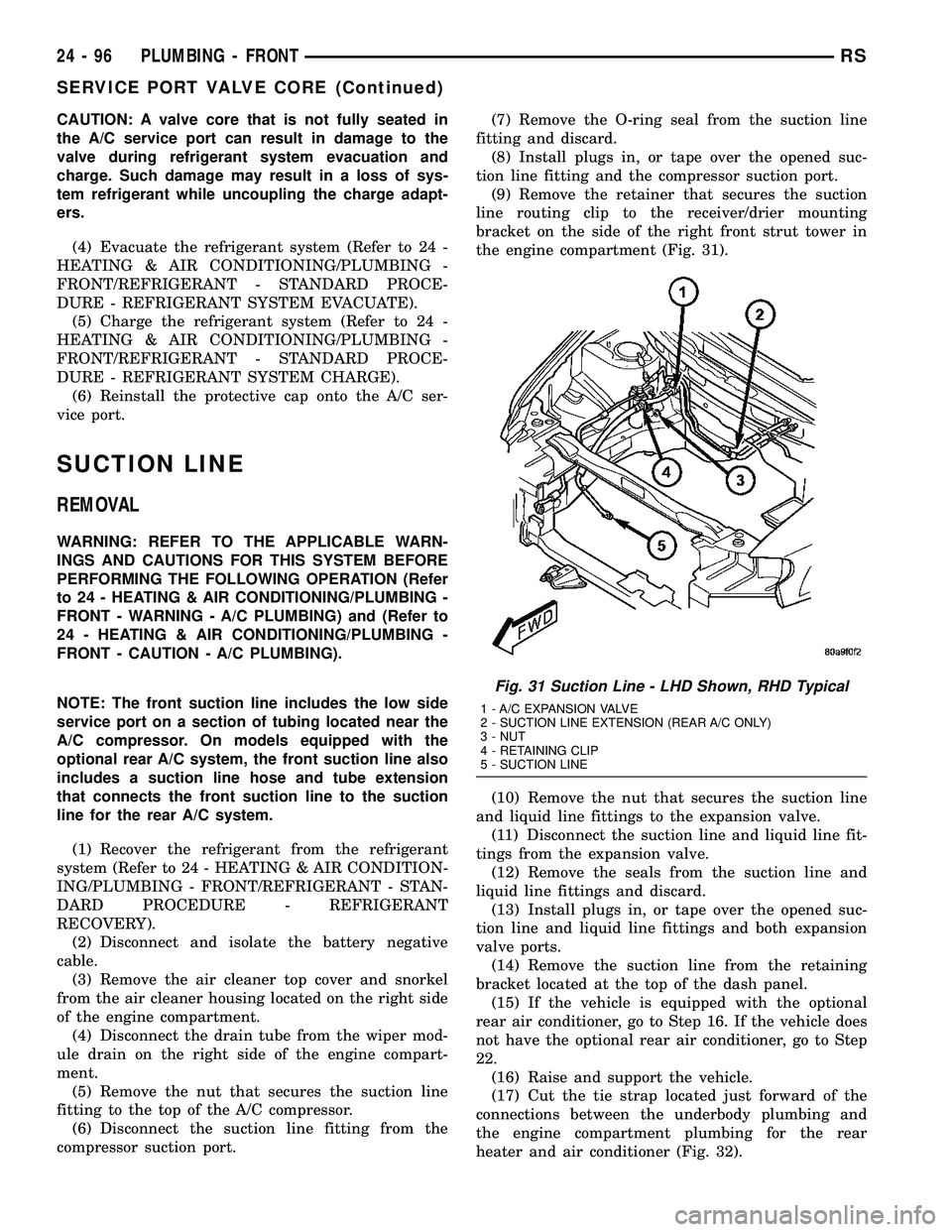
the engine compartment (Fig. 31).
(10) Remove the nut that secures the suction line
and liquid line fittings to the expansion valve.
(11) Disconnect the suction line and liquid line fit-
tings from the expansion valve.
(12) Remove the seals from the suction line and
liquid line fittings and discard.
(13) Install plugs in, or tape over the opened suc-
tion line and liquid line fittings and both expansion
valve ports.
(14) Remove the suction line from the retaining
bracket located at the top of the dash panel.
(15) If the vehicle is equipped with the optional
rear air conditioner, go to Step 16. If the vehicle does
not have the optional rear air conditioner, go to Step
22.
(16) Raise and support the vehicle.
(17) Cut the tie strap located just forward of the
connections between the underbody plumbing and
the engine compartment plumbing for the rear
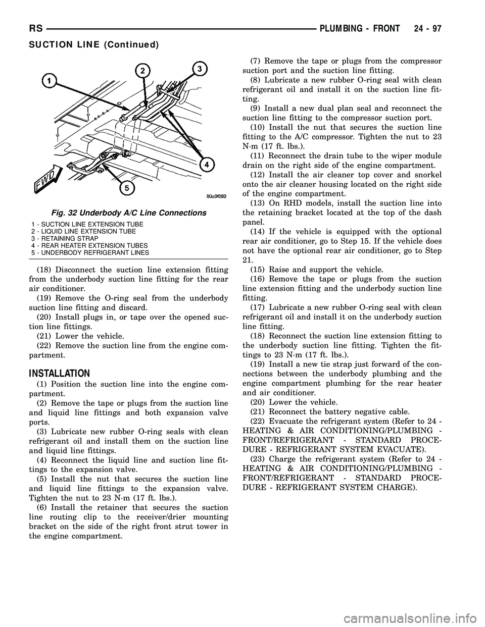
heater and air conditioner (Fig. 32).
Fig. 31 Suction Line - LHD Shown, RHD Typical
1 - A/C EXPANSION VALVE
2 - SUCTION LINE EXTENSION (REAR A/C ONLY)
3 - NUT
4 - RETAINING CLIP
5 - SUCTION LINE
24 - 96 PLUMBING - FRONTRS
SERVICE PORT VALVE CORE (Continued)
Page 2248 of 2339
(18) Disconnect the suction line extension fitting
from the underbody suction line fitting for the rear
air conditioner.
(19) Remove the O-ring seal from the underbody
suction line fitting and discard.
(20) Install plugs in, or tape over the opened suc-
tion line fittings.
(21) Lower the vehicle.
(22) Remove the suction line from the engine com-
partment.
INSTALLATION
(1) Position the suction line into the engine com-
partment.
(2) Remove the tape or plugs from the suction line
and liquid line fittings and both expansion valve
ports.
(3) Lubricate new rubber O-ring seals with clean
refrigerant oil and install them on the suction line
and liquid line fittings.
(4) Reconnect the liquid line and suction line fit-
tings to the expansion valve.
(5) Install the nut that secures the suction line
and liquid line fittings to the expansion valve.
Tighten the nut to 23 N´m (17 ft. lbs.).
(6) Install the retainer that secures the suction
line routing clip to the receiver/drier mounting
bracket on the side of the right front strut tower in
the engine compartment.(7) Remove the tape or plugs from the compressor
suction port and the suction line fitting.
(8) Lubricate a new rubber O-ring seal with clean
refrigerant oil and install it on the suction line fit-
ting.
(9) Install a new dual plan seal and reconnect the
suction line fitting to the compressor suction port.
(10) Install the nut that secures the suction line
fitting to the A/C compressor. Tighten the nut to 23
N´m (17 ft. lbs.).
(11) Reconnect the drain tube to the wiper module
drain on the right side of the engine compartment.
(12) Install the air cleaner top cover and snorkel
onto the air cleaner housing located on the right side
of the engine compartment.
(13) On RHD models, install the suction line into
the retaining bracket located at the top of the dash
panel.
(14) If the vehicle is equipped with the optional
rear air conditioner, go to Step 15. If the vehicle does
not have the optional rear air conditioner, go to Step
21.
(15) Raise and support the vehicle.
(16) Remove the tape or plugs from the suction
line extension fitting and the underbody suction line
fitting.
(17) Lubricate a new rubber O-ring seal with clean
refrigerant oil and install it on the underbody suction
line fitting.
(18) Reconnect the suction line extension fitting to
the underbody suction line fitting. Tighten the fit-
tings to 23 N´m (17 ft. lbs.).
(19) Install a new tie strap just forward of the con-
nections between the underbody plumbing and the
engine compartment plumbing for the rear heater
and air conditioner.
(20) Lower the vehicle.
(21) Reconnect the battery negative cable.
(22) Evacuate the refrigerant system (Refer to 24 -
HEATING & AIR CONDITIONING/PLUMBING -
FRONT/REFRIGERANT - STANDARD PROCE-
DURE - REFRIGERANT SYSTEM EVACUATE).
(23) Charge the refrigerant system (Refer to 24 -
HEATING & AIR CONDITIONING/PLUMBING -
FRONT/REFRIGERANT - STANDARD PROCE-
DURE - REFRIGERANT SYSTEM CHARGE).
Fig. 32 Underbody A/C Line Connections
1 - SUCTION LINE EXTENSION TUBE
2 - LIQUID LINE EXTENSION TUBE
3 - RETAINING STRAP
4 - REAR HEATER EXTENSION TUBES
5 - UNDERBODY REFRIGERANT LINES
RSPLUMBING - FRONT24-97
SUCTION LINE (Continued)
Page 2256 of 2339
INSTALLATION
(1) Install the front underbody heater inlet and
return hoses by carefully twisting the hoses back and
forth on the underbody tubes, while gently pushing
them onto the end of the tubes.
CAUTION:
DO NOT apply excessive pressure on heater tubes
or connections when removing heater hoses.
Excessive pressure may damage or deform the
tubes, causing an engine coolant leak.
(2) Using spring tension clamp pliers, compress
and slide the clamps that secure each end of the
heater hose over the tubes. Release the clamp when
it is over the tube.
(3) Refill the engine cooling system (Refer to 7 -
COOLING - STANDARD PROCEDURE - COOLING
SYSTEM REFILL).
LIQUID LINE
REMOVAL
WARNING: REFER TO THE APPLICABLE WARN-
INGS AND CAUTIONS FOR THIS SYSTEM BEFORE
PERFORMING THE FOLLOWING OPERATION (Refer
to 24 - HEATING & AIR CONDITIONING/PLUMBING -
FRONT - WARNING - A/C PLUMBING) and (Refer to
24 - HEATING & AIR CONDITIONING/PLUMBING -
FRONT - CAUTION - A/C PLUMBING).
NOTE: On models equipped with the optional rear
A/C system, the rear section of the front air condi-
tioner liquid line also includes a liquid line hose
and tube extension that connects the front liquid
line to the underbody liquid line for the rear A/C
system.
(1) Recover the refrigerant from the refrigerant
system (Refer to 24 - HEATING & AIR CONDITION-
ING/PLUMBING - FRONT/REFRIGERANT - STAN-
DARD PROCEDURE - REFRIGERANT
RECOVERY).
(2) Disconnect and isolate the battery negative
cable.
(3) Remove the air cleaner housing from the right
side of the engine compartment.
(4) Disconnect the drain tube from the wiper mod-
ule drain on the right side of the engine compart-
ment.
(5) Remove the A/C pressure transducer (Refer to
24 - HEATING & AIR CONDITIONING/CONTROLS
- FRONT/A/C PRESSURE TRANSDUCER -
REMOVAL).(6) If equipped, remove the nut that secures the
A/C ground strap to the weld stud on the top of the
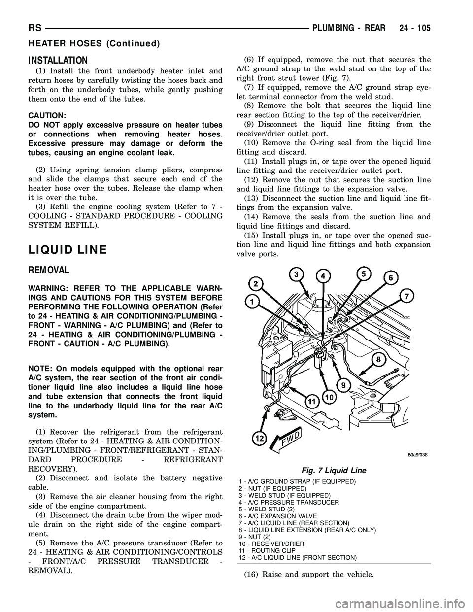
right front strut tower (Fig. 7).
(7) If equipped, remove the A/C ground strap eye-
let terminal connector from the weld stud.
(8) Remove the bolt that secures the liquid line
rear section fitting to the top of the receiver/drier.
(9) Disconnect the liquid line fitting from the
receiver/drier outlet port.
(10) Remove the O-ring seal from the liquid line
fitting and discard.
(11) Install plugs in, or tape over the opened liquid
line fitting and the receiver/drier outlet port.
(12) Remove the nut that secures the suction line
and liquid line fittings to the expansion valve.
(13) Disconnect the suction line and liquid line fit-
tings from the expansion valve.
(14) Remove the seals from the suction line and
liquid line fittings and discard.
(15) Install plugs in, or tape over the opened suc-
tion line and liquid line fittings and both expansion
valve ports.
(16) Raise and support the vehicle.
Fig. 7 Liquid Line
1 - A/C GROUND STRAP (IF EQUIPPED)
2 - NUT (IF EQUIPPED)
3 - WELD STUD (IF EQUIPPED)
4 - A/C PRESSURE TRANSDUCER
5 - WELD STUD (2)
6 - A/C EXPANSION VALVE
7 - A/C LIQUID LINE (REAR SECTION)
8 - LIQUID LINE EXTENSION (REAR A/C ONLY)
9 - NUT (2)
10 - RECEIVER/DRIER
11 - ROUTING CLIP
12 - A/C LIQUID LINE (FRONT SECTION)
RSPLUMBING - REAR24 - 105
HEATER HOSES (Continued)
Page 2257 of 2339
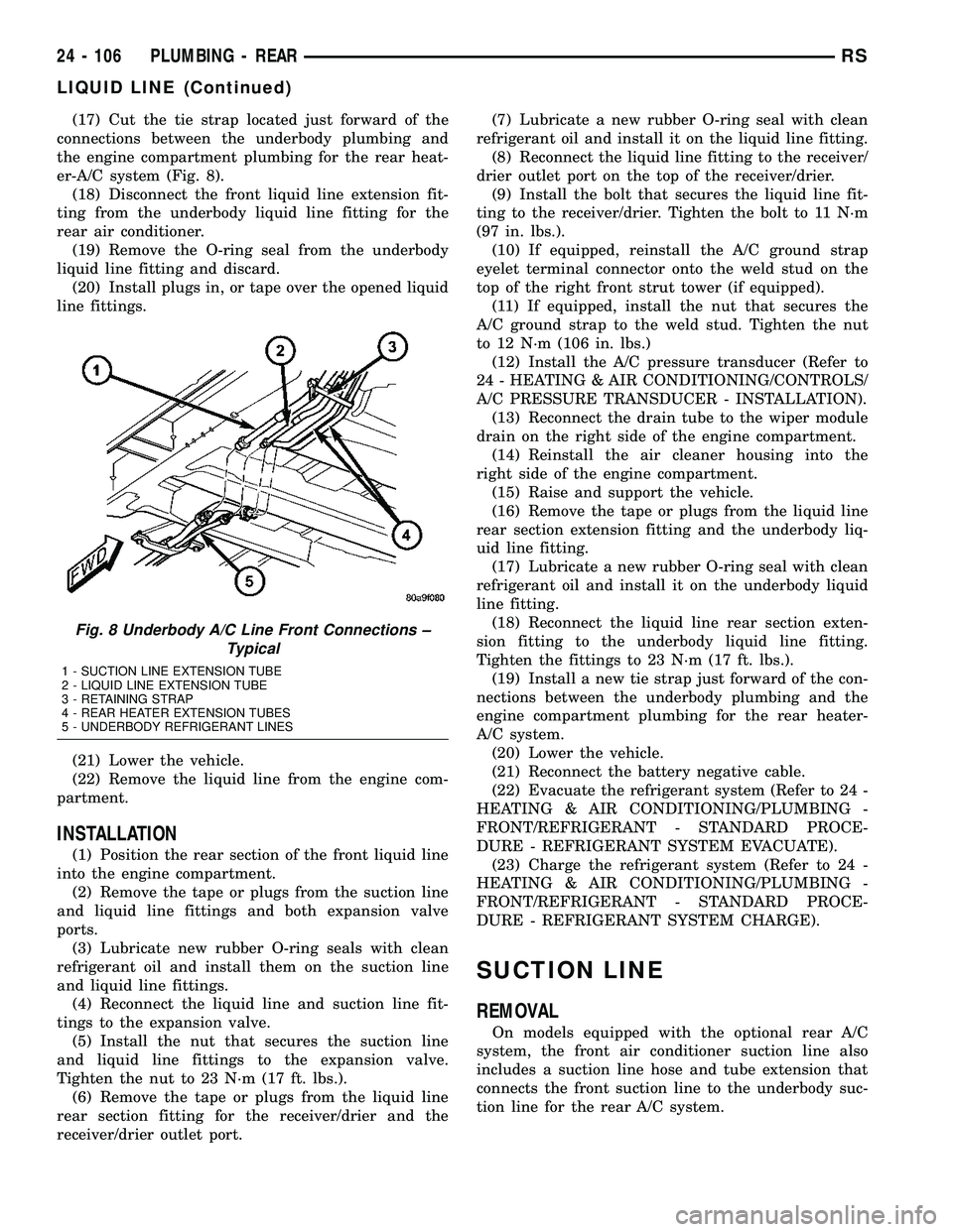
(17) Cut the tie strap located just forward of the
connections between the underbody plumbing and
the engine compartment plumbing for the rear heat-
er-A/C system (Fig. 8).
(18) Disconnect the front liquid line extension fit-
ting from the underbody liquid line fitting for the
rear air conditioner.
(19) Remove the O-ring seal from the underbody
liquid line fitting and discard.
(20) Install plugs in, or tape over the opened liquid
line fittings.
(21) Lower the vehicle.
(22) Remove the liquid line from the engine com-
partment.
INSTALLATION
(1) Position the rear section of the front liquid line
into the engine compartment.
(2) Remove the tape or plugs from the suction line
and liquid line fittings and both expansion valve
ports.
(3) Lubricate new rubber O-ring seals with clean
refrigerant oil and install them on the suction line
and liquid line fittings.
(4) Reconnect the liquid line and suction line fit-
tings to the expansion valve.
(5) Install the nut that secures the suction line
and liquid line fittings to the expansion valve.
Tighten the nut to 23 N´m (17 ft. lbs.).
(6) Remove the tape or plugs from the liquid line
rear section fitting for the receiver/drier and the
receiver/drier outlet port.(7) Lubricate a new rubber O-ring seal with clean
refrigerant oil and install it on the liquid line fitting.
(8) Reconnect the liquid line fitting to the receiver/
drier outlet port on the top of the receiver/drier.
(9) Install the bolt that secures the liquid line fit-
ting to the receiver/drier. Tighten the bolt to 11 N´m
(97 in. lbs.).
(10) If equipped, reinstall the A/C ground strap
eyelet terminal connector onto the weld stud on the
top of the right front strut tower (if equipped).
(11) If equipped, install the nut that secures the
A/C ground strap to the weld stud. Tighten the nut
to 12 N´m (106 in. lbs.)
(12) Install the A/C pressure transducer (Refer to
24 - HEATING & AIR CONDITIONING/CONTROLS/
A/C PRESSURE TRANSDUCER - INSTALLATION).
(13) Reconnect the drain tube to the wiper module
drain on the right side of the engine compartment.
(14) Reinstall the air cleaner housing into the
right side of the engine compartment.
(15) Raise and support the vehicle.
(16) Remove the tape or plugs from the liquid line
rear section extension fitting and the underbody liq-
uid line fitting.
(17) Lubricate a new rubber O-ring seal with clean
refrigerant oil and install it on the underbody liquid
line fitting.
(18) Reconnect the liquid line rear section exten-
sion fitting to the underbody liquid line fitting.
Tighten the fittings to 23 N´m (17 ft. lbs.).
(19) Install a new tie strap just forward of the con-
nections between the underbody plumbing and the
engine compartment plumbing for the rear heater-
A/C system.
(20) Lower the vehicle.
(21) Reconnect the battery negative cable.
(22) Evacuate the refrigerant system (Refer to 24 -
HEATING & AIR CONDITIONING/PLUMBING -
FRONT/REFRIGERANT - STANDARD PROCE-
DURE - REFRIGERANT SYSTEM EVACUATE).
(23) Charge the refrigerant system (Refer to 24 -
HEATING & AIR CONDITIONING/PLUMBING -
FRONT/REFRIGERANT - STANDARD PROCE-
DURE - REFRIGERANT SYSTEM CHARGE).
SUCTION LINE
REMOVAL
On models equipped with the optional rear A/C
system, the front air conditioner suction line also
includes a suction line hose and tube extension that
connects the front suction line to the underbody suc-
tion line for the rear A/C system.
Fig. 8 Underbody A/C Line Front Connections ±
Typical
1 - SUCTION LINE EXTENSION TUBE
2 - LIQUID LINE EXTENSION TUBE
3 - RETAINING STRAP
4 - REAR HEATER EXTENSION TUBES
5 - UNDERBODY REFRIGERANT LINES
24 - 106 PLUMBING - REARRS
LIQUID LINE (Continued)
Page 2258 of 2339
WARNING: REFER TO THE APPLICABLE WARN-
INGS AND CAUTIONS FOR THIS SYSTEM BEFORE
PERFORMING THE FOLLOWING OPERATION (Refer
to 24 - HEATING & AIR CONDITIONING/PLUMBING -
FRONT - WARNING - A/C PLUMBING) and (Refer to
24 - HEATING & AIR CONDITIONING/PLUMBING -
FRONT - CAUTION - A/C PLUMBING).
(1) Recover the refrigerant from the refrigerant
system (Refer to 24 - HEATING & AIR CONDITION-
ING/PLUMBING - FRONT/REFRIGERANT - STAN-
DARD PROCEDURE - REFRIGERANT
RECOVERY).
(2) Disconnect and isolate the battery negative
cable.
(3) Remove the air cleaner top cover and snorkel
from the air cleaner housing located on the right side
of the engine compartment.
(4) Disconnect the drain tube from the wiper mod-
ule drain on the right side of the engine compart-
ment.
(5) Remove the nut that secures the suction line
fitting to the top of the compressor.
(6) Disconnect the suction line fitting from the
compressor suction port.
(7) Remove the seal from the suction line fitting
and discard.
(8) Install plugs in, or tape over the opened suc-
tion line fitting and the compressor suction port.
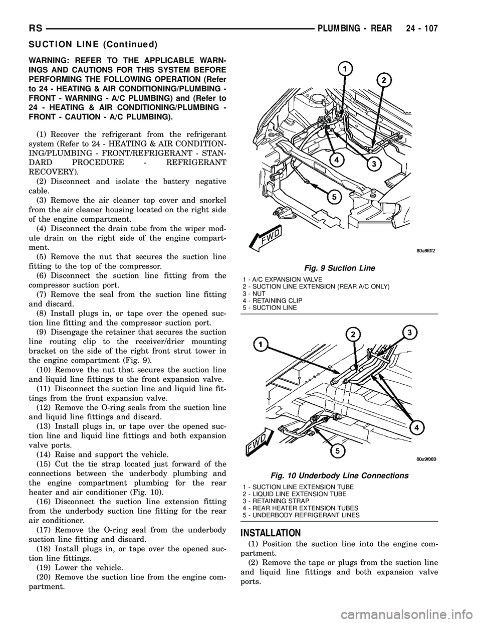
(9) Disengage the retainer that secures the suction
line routing clip to the receiver/drier mounting
bracket on the side of the right front strut tower in
the engine compartment (Fig. 9).
(10) Remove the nut that secures the suction line
and liquid line fittings to the front expansion valve.
(11) Disconnect the suction line and liquid line fit-
tings from the front expansion valve.
(12) Remove the O-ring seals from the suction line
and liquid line fittings and discard.
(13) Install plugs in, or tape over the opened suc-
tion line and liquid line fittings and both expansion
valve ports.
(14) Raise and support the vehicle.
(15) Cut the tie strap located just forward of the
connections between the underbody plumbing and
the engine compartment plumbing for the rear
heater and air conditioner (Fig. 10).
(16) Disconnect the suction line extension fitting
from the underbody suction line fitting for the rear
air conditioner.
(17) Remove the O-ring seal from the underbody
suction line fitting and discard.
(18) Install plugs in, or tape over the opened suc-
tion line fittings.
(19) Lower the vehicle.
(20) Remove the suction line from the engine com-
partment.
INSTALLATION
(1) Position the suction line into the engine com-
partment.
(2) Remove the tape or plugs from the suction line
and liquid line fittings and both expansion valve
ports.
Fig. 9 Suction Line
1 - A/C EXPANSION VALVE
2 - SUCTION LINE EXTENSION (REAR A/C ONLY)
3 - NUT
4 - RETAINING CLIP
5 - SUCTION LINE
Fig. 10 Underbody Line Connections
1 - SUCTION LINE EXTENSION TUBE
2 - LIQUID LINE EXTENSION TUBE
3 - RETAINING STRAP
4 - REAR HEATER EXTENSION TUBES
5 - UNDERBODY REFRIGERANT LINES
RSPLUMBING - REAR24 - 107
SUCTION LINE (Continued)
Page 2259 of 2339
(3) Lubricate new rubber O-ring seals with clean
refrigerant oil and install them on the suction line
and liquid line fittings.
(4) Reconnect the liquid line and suction line fit-
tings to the expansion valve.
(5) Install the nut that secures the suction line
and liquid line fittings to the front expansion valve.
Tighten the nut to 23 N´m (17 ft. lbs.).
(6) Engage the retainer that secures the suction
line routing clip to the receiver/drier mounting
bracket on the side of the right front strut tower in
the engine compartment.
(7) Remove the tape or plugs from the compressor
suction port and the suction line fitting.
(8) Lubricate a new rubber O-ring seal with clean
refrigerant oil and install it on the suction line fit-
ting.
(9) Reconnect the suction line fitting to the com-
pressor suction port.
(10) Install the nut that secures the suction line
fitting to the A/C compressor. Tighten the nut to 23
N´m (17 ft. lbs.).
(11) Reconnect the drain tube to the wiper module
drain on the right side of the engine compartment.
(12) Reinstall the air cleaner top cover and snorkel
onto the air cleaner housing located on the right side
of the engine compartment.
(13) Reconnect the battery negative cable.
(14) Raise and support the vehicle.
(15) Remove the tape or plugs from the suction
line extension fitting and the underbody suction line
fitting.
(16) Lubricate a new rubber O-ring seal with clean
refrigerant oil and install it on the underbody suction
line fitting.(17) Reconnect the suction line extension fitting to
the underbody suction line fitting. Tighten the fitting
to 23 N´m (17 ft. lbs.).
(18) Install a new tie strap just forward of the con-
nections between the underbody plumbing and the
engine compartment plumbing for the rear heater
and air conditioner.
(19) Lower the vehicle.
(20) Evacuate the refrigerant system (Refer to 24 -
HEATING & AIR CONDITIONING/PLUMBING -
FRONT/REFRIGERANT - STANDARD PROCE-
DURE - REFRIGERANT SYSTEM EVACUATE).
(21) Charge the refrigerant system (Refer to 24 -
HEATING & AIR CONDITIONING/PLUMBING -
FRONT/REFRIGERANT - STANDARD PROCE-
DURE - REFRIGERANT SYSTEM CHARGE).
UNDERBODY LINES
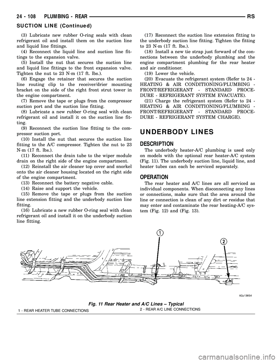
DESCRIPTION
The underbody heater-A/C plumbing is used only
on models with the optional rear heater-A/C system
(Fig. 11). The underbody suction line, liquid line, and
heater tubes can each be serviced separately.
OPERATION
The rear heater and A/C lines are all serviced as
individual components. When disconnecting any lines
or connections, make sure that the area around the
line or connection is clean of any dirt or residue that
may enter and contaminate the rear heating-A/C sys-
tem (Fig. 12) and (Fig. 13).
Fig. 11 Rear Heater and A/C Lines ± Typical
1 - REAR HEATER TUBE CONNECTIONS2 - REAR A/C LINE CONNECTIONS
24 - 108 PLUMBING - REARRS
SUCTION LINE (Continued)
Page 2268 of 2339
FUEL DOSING PUMP
DESCRIPTION
The dosing pump is a combined delivery, dosing
and shut-off system for the fuel supply to the supple-
mental cabin heater from the vehicle fuel tank.
OPERATION
The dosing pump is an electrically operated pump
that receives its operation instructions from the sup-
plemental cabin heater control module. The pump
supplies diesel fuel from the vehicle fuel tank to the
cabin heater.
REMOVAL
NOTE: The dosing pump is serviceable without
removing the supplemental cabin heater from the
vehicle.
(1) Disconnect and isolate the negative battery
cable.
CAUTION: Make sure that the hoist is properly posi-
tioned under the vehicle to prevent damage to the
flexible section of the cabin heater exhaust tube.
(2) Raise and support the vehicle.
(3) Disconnect the wiring harness connector to the
dosing pump by depressing the integral spring and
pulling the connector away from the pump.
NOTE: Utilize an approved fuel storage container to
catch any residual fuel that may drain from the
heater fuel hose or the dosing pump.
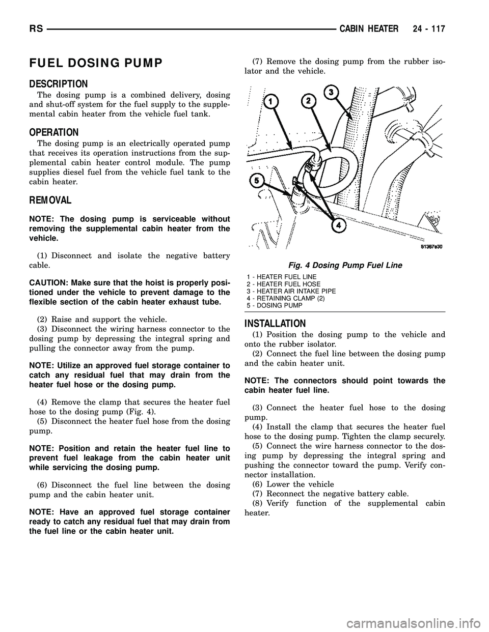
(4) Remove the clamp that secures the heater fuel
hose to the dosing pump (Fig. 4).
(5) Disconnect the heater fuel hose from the dosing
pump.
NOTE: Position and retain the heater fuel line to
prevent fuel leakage from the cabin heater unit
while servicing the dosing pump.
(6) Disconnect the fuel line between the dosing
pump and the cabin heater unit.
NOTE: Have an approved fuel storage container
ready to catch any residual fuel that may drain from
the fuel line or the cabin heater unit.(7) Remove the dosing pump from the rubber iso-
lator and the vehicle.
INSTALLATION
(1) Position the dosing pump to the vehicle and
onto the rubber isolator.
(2) Connect the fuel line between the dosing pump
and the cabin heater unit.
NOTE: The connectors should point towards the
cabin heater fuel line.
(3) Connect the heater fuel hose to the dosing
pump.
(4) Install the clamp that secures the heater fuel
hose to the dosing pump. Tighten the clamp securely.
(5) Connect the wire harness connector to the dos-
ing pump by depressing the integral spring and
pushing the connector toward the pump. Verify con-
nector installation.
(6) Lower the vehicle
(7) Reconnect the negative battery cable.
(8) Verify function of the supplemental cabin
heater.
Fig. 4 Dosing Pump Fuel Line
1 - HEATER FUEL LINE
2 - HEATER FUEL HOSE
3 - HEATER AIR INTAKE PIPE
4 - RETAINING CLAMP (2)
5 - DOSING PUMP
RSCABIN HEATER24 - 117