2005 CHRYSLER CARAVAN battery
[x] Cancel search: batteryPage 1948 of 2339

SUNROOF
TABLE OF CONTENTS
page page
SUNROOF
DESCRIPTION........................169
DIAGNOSIS AND TESTING
SUNROOF DIAGNOSIS AND TESTING....169
DRAIN TUBE
REMOVAL............................172
INSTALLATION........................172
GLASS PANEL
REMOVAL............................173
INSTALLATION........................173
ADJUSTMENTS
SUNROOF GLASS PANEL ADJUSTMENT . . 173
SUNROOF ASSEMBLY
REMOVAL............................173
INSTALLATION........................173
SUNSHADE
REMOVAL............................173INSTALLATION........................173
WIND DEFLECTOR
REMOVAL............................174
INSTALLATION........................174
WATER CHANNEL
REMOVAL............................174
INSTALLATION........................174
SUNROOF MOTOR
REMOVAL............................174
INSTALLATION........................174
ADJUSTMENTS
ADJUSTMENT.......................175
SUNROOF SWITCH
REMOVAL............................176
INSTALLATION........................176
SUNROOF
DESCRIPTION
WARNING: Keep fingers and other body parts out
of sunroof opening at all times.
The sun roof features consists of: (Fig. 1)
²Sun roof glass
²Sun roof sun shade
The sunroof power sliding glass panel and sun-
shade can be positioned anywhere along its travel,
rearward of glass panel front edge.
The sunroof is electrically operated from a switch
located in the overhead console. To operate the sun-
roof the ignition switch must be in the Accessory or
On/Run position. Both switchs are a rocker style
design that open or close the sunroof. When pressing
and releasing the open button once, the sunroof will
express open to the comfort stop and the wind deflec-
tor will raise. If the button is pressed a second time,
the sunroof will continue to open to full travel unless
the button is released, at which time it will stop in
that position. Pressing and holding the close button
will close the sunroof. If the close button is released
before the glass fully closes, the sunroof will stop in
that position. The vent switch operates in a similar
manor. The sunroof will also operate for up to fifteen
minutes after the ignition key is turned off for cus-
tomer comfort and convenance while parking.
DIAGNOSIS AND TESTING
SUNROOF DIAGNOSIS AND TESTING
Refer to Sunroof Diagnostic Chart for possible
causes. Before beginning sunroof diagnostics verify
that all other power accessories are in proper operat-
ing condition. If not, a common electrical problem
may exist. Refer to Wiring Diagrams, in this publica-
tion for circuit, splice and component descriptions.
Check the condition of the circuit protection (20 amp
circuit breaker in the Junction Block). Inspect all
wiring connector pins for proper engagement and
continuity. Check for battery voltage at the power
sunroof controller, refer to Wiring Diagrams, for cir-
cuit information. If battery voltage of more than 10
volts is detected at the controller, proceed with the
following tests (the controller will not operate at less
than 10 volts).
Before beginning diagnosis for wind noise or water
leaks, verify that the problem was not caused by
releasing the control switch before the sunroof was
fully closed. The sunroof module has a water-man-
agement system. If however, the sunroof glass is in a
partial closed position, high pressure water may be
forced beyond the water management system bound-
aries and onto the headlining.
RSSUNROOF23 - 169
Page 1951 of 2339
SYMPTOM POSSIBLE CAUSE
Sunshade will not function or does not
operate smoothlySunshade feet are missing, broken or loose.
No lubracation in track.
Track obstructions or interference.
Glass movement not consistant or glass does
not operate smoothlyGlass and Track timing.
Glass and Track alignment
Cables and Guide alignment
WATER DRAINAGE AND WIND NOISE DIAGNOSIS
The sliding glass panel is designed to seal water
entry with a snug fit between the roof and the seal.
The fit can be checked by inserting a piece of paper
between the roof and the seal. The piece of paper
should have some resistance when pulled out when
the glass panel is in the closed position. Excessive
wind noise could result if the gap clearances are
exceeded. The sunroof glass panel may need to be
adjusted. Refer to Sunroof Glass Panel Adjustment
for proper procedures.
Adequate drainage is provided by a drain trough in
the sunroof housing which encircles the sliding glass
panel and leads to drain hoses. If a wet headliner or
other water leak complaints are encountered, before
performing any adjustments, first ensure that the
drainage system is not plugged or disconnected. Use
a pint container to pour water into the sunroof hous-
ing drain trough. If water flow is restricted in any of
the four drain holes, use compressed air to blow out
any material plugging the drain system. Retest sys-
tem again.
To further check for a disconnected drain hose:
(1) Remove A-pillar trim, sun visors, and map
lamps/mini console.
(2) Remove sunroof opening trim lace. Refer to
Sunroof Opening Trim Lace.
NOTE: Care must be taken not to fold or kink the
headliner upon removal.
(3) Lower headliner as necessary to gain access to
sunroof housing drain tubes. Refer to Headlining
Removal and Installation for proper procedures.
(4) Repair as necessary.
DRAIN TUBE
REMOVAL
FRONT HOSES
NOTE: Front A-pillars are filled with sound deaden-
ing foam and the front drain tubes are sealed into
the pillars.
(1) Move glass panel to the fully closed position.
(2) Disconnect negative battery cable.
(3) Remove headliner (Refer to 23 - BODY/INTE-
RIOR/HEADLINER - REMOVAL).
(4) Disconnect the drain hose from the sunroof
housing (Fig. 1).
(5) Drain any liquid from hose connection, repair
as necessary.
REAR HOUSING HOSE
(1) Move glass panel to the fully closed position.
(2) Disconnect negative battery cable.
(3) Remove headliner (Refer to 23 - BODY/INTE-
RIOR/HEADLINER - REMOVAL).
(4) Remove third seat or seats from vehicle.
(5) Remove second seat belt lower anchor.
(6) Remove third seat lower anchor.
(7) Remove quarter trim bolster.
(8) Remove trim panel screws.
(9) Remove quarter trim panel
(10) Disconnect the drain hose from the sunroof
housing. (Fig. 1).
(11) Drain any liquid from hose connection, if nec-
essary, and remove tube.
INSTALLATION
FRONT HOSES
(1) Connect the new drain hose to the sunroof
housing and test drainage (Fig. 1).
(2) Install headliner (Refer to 23 - BODY/INTERI-
OR/HEADLINER - INSTALLATION).
(3) Install sunroof opening trim lace.
(4) Connect the control switch wire connector and
install control switch.
23 - 172 SUNROOFRS
SUNROOF (Continued)
Page 1952 of 2339
(5) Verify sunroof operation and alignment.
REAR HOUSING HOSE
(1) Connect the new drain hose to the sunroof
housing and test drainage (Fig. 1).
(2) Install headliner(Refer to 23 - BODY/INTERI-
OR/HEADLINER - INSTALLATION).
(3) Install sunroof opening trim lace.
(4) Connect the control switch wire connector and
install control switch.
(5) Verify sunroof operation and alignment.
GLASS PANEL
REMOVAL
(1) Move the glass panel to the vent position.
(2) Slide sunshade rearward to the open position.
(3) Remove the glass panel screws (Fig. 1).
(4) Lift off glass panel and remove from vehicle.
INSTALLATION
(1) Position glass panel on to mechanism lift arms.
(2) Start the attaching screws, and hand tighten
(Fig. 1).
(3) Adjust sunroof glass to fit flush with roof
line(Refer to 23 - BODY/SUNROOF/GLASS PANEL -
ADJUSTMENTS).
(4) Verify sunroof operation and alignment.
ADJUSTMENTS
SUNROOF GLASS PANEL ADJUSTMENT
(1) Move the sunshade rearward to the open posi-
tion.
(2) Move the sunroof glass panel to the fully closed
position.
(3) Loosen the forward attaching screws on each
side enough to make the front of the glass to adjust
up or down.
(4) Adjust the front surface of the sunroof glass
panel 0.00 mm to 1.75 mm (0.00 in. to 0.07 in.) below
the top surface of the roof.
(5) Tighten the front glass panel attaching screws
to 3.5 N´m (31 in. lbs.) torque (Fig. 1).
(6) Loosen the rear screws on each side enough to
make the rear adjustment (Fig. 1).
(7) Adjust the rear surface of the sunroof glass
panel 0.00 mm to 1.75 mm (0.03 in. to 0.07 in.) above
the top surface of the roof.
(8) Tighten the rear glass panel attaching screws
to 3.5 N´m (31 in. lbs.) torque (Fig. 1).
(9) Check for proper fit. If not OK, repeat glass
panel adjustment.
SUNROOF ASSEMBLY
REMOVAL
(1) Move glass panel to the fully closed position.
(2) Disconnect battery negative cable.
(3) Remove headliner (Refer to 23 - BODY/INTE-
RIOR/HEADLINER - REMOVAL).
(4) Disconnect the four drain tubes from sunroof
housing (Fig. 1).
(5) Loosen fasteners attaching sunroof assembly
(Fig. 1).
(6) With the aid of a helper, support the sunroof
and remove the fasteners attaching sunroof assembly
to roof panel (Fig. 1).
(7) Remove sunroof from vehicle.
INSTALLATION
(1) Raise sunroof module assembly and guide it
carefully into position.
(2) While supporting the sunroof assembly tighten
the attaching screws (Fig. 1). Tighten to 6 N´m (53
in. lbs.) torque.
(3) Connect the drain tubes to the sunroof (Fig. 1).
(4) Connect battery negative cable.
(5) Test sunroof operation, adjust as necessary(Re-
fer to 23 - BODY/SUNROOF/GLASS PANEL -
ADJUSTMENTS).
(6) Install headliner (Refer to 23 - BODY/INTERI-
OR/HEADLINER - INSTALLATION).
(7) Install sunroof opening trim lace position(Refer
to 23 - BODY/SUNROOF/OPENING TRIM LACE -
INSTALLATION).
SUNSHADE
REMOVAL
(1) Place the sunroof glass panel in the vent posi-
tion.
(2) Remove glass panel (Refer to 23 - BODY/SUN-
ROOF/GLASS PANEL - REMOVAL).
(3) Remove water channel (Fig. 1).
(4) Cycle sunroof motor to the open position.
(5) Move sunshade towards the closed position
stopping three to four inches from the closed position.
(6) Depress the spring feet clips on one side of the
sun shade.
(7) Remove sunshade.
INSTALLATION
(1) Place one side of the sunshade spring feet clips
into the top track U-frame.
(2) Depress the both releasing clips on the other
side to allow them to go into the top track U-frame.
(3) Move sunshade to the open position.
(4) Install water channel (Fig. 1).
RSSUNROOF23 - 173
DRAIN TUBE (Continued)
Page 1953 of 2339
(5) Verify that the sunshade move back and forth
properly.
(6) Cycle sunroof towards the closed position.
(7) Install glass panel (Refer to 23 - BODY/SUN-
ROOF/GLASS PANEL - INSTALLATION).
WIND DEFLECTOR
REMOVAL
(1) Fully open sunroof glass panel.
(2) Disconnect negative battery cable.
(3) Remove sunroof assembly (Refer to 23 - BODY/
SUNROOF/MODULE ASSEMBLY - REMOVAL).
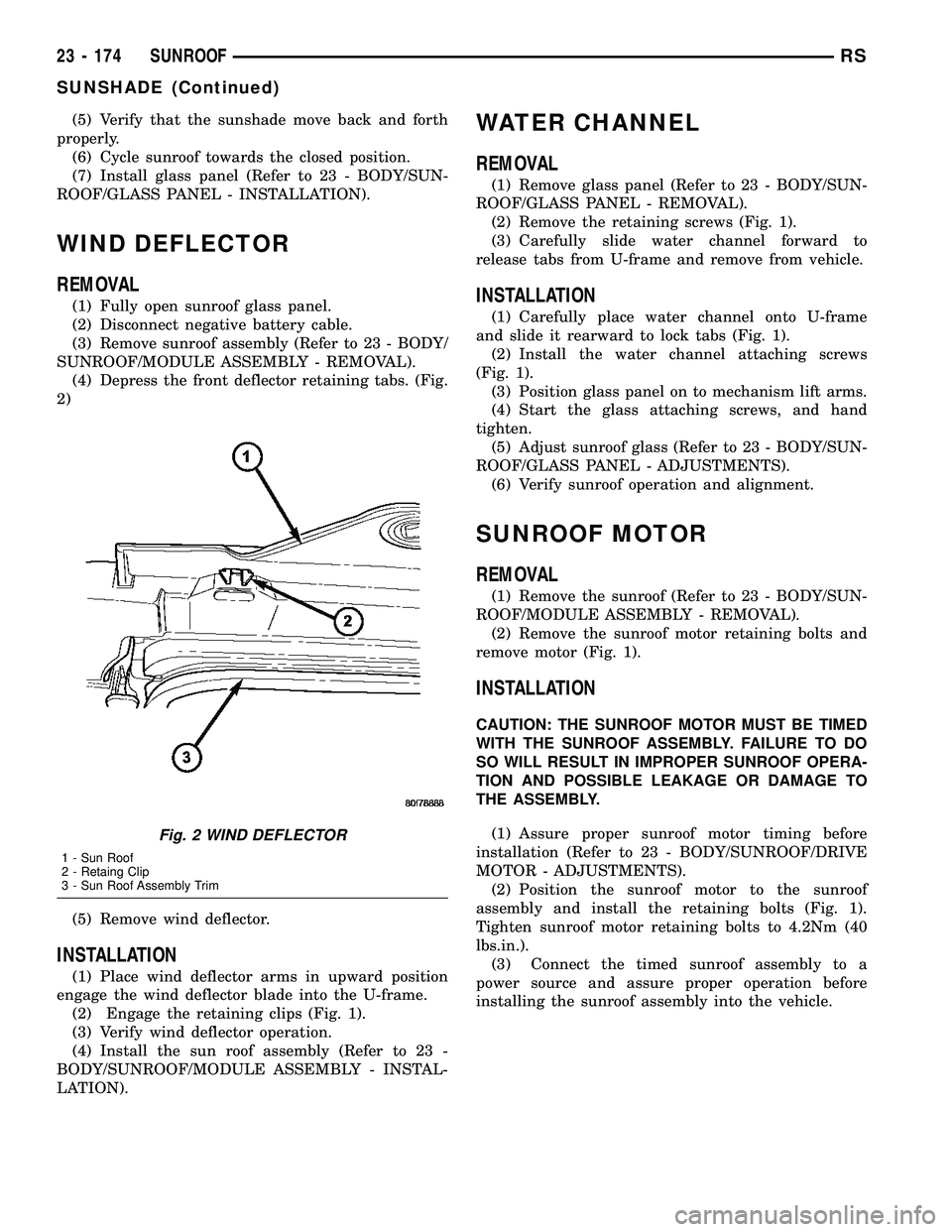
(4) Depress the front deflector retaining tabs. (Fig.
2)
(5) Remove wind deflector.
INSTALLATION
(1) Place wind deflector arms in upward position
engage the wind deflector blade into the U-frame.
(2) Engage the retaining clips (Fig. 1).
(3) Verify wind deflector operation.
(4) Install the sun roof assembly (Refer to 23 -
BODY/SUNROOF/MODULE ASSEMBLY - INSTAL-
LATION).
WATER CHANNEL
REMOVAL
(1) Remove glass panel (Refer to 23 - BODY/SUN-
ROOF/GLASS PANEL - REMOVAL).
(2) Remove the retaining screws (Fig. 1).
(3) Carefully slide water channel forward to
release tabs from U-frame and remove from vehicle.
INSTALLATION
(1) Carefully place water channel onto U-frame
and slide it rearward to lock tabs (Fig. 1).
(2) Install the water channel attaching screws
(Fig. 1).
(3) Position glass panel on to mechanism lift arms.
(4) Start the glass attaching screws, and hand
tighten.
(5) Adjust sunroof glass (Refer to 23 - BODY/SUN-
ROOF/GLASS PANEL - ADJUSTMENTS).
(6) Verify sunroof operation and alignment.
SUNROOF MOTOR
REMOVAL
(1) Remove the sunroof (Refer to 23 - BODY/SUN-
ROOF/MODULE ASSEMBLY - REMOVAL).
(2) Remove the sunroof motor retaining bolts and
remove motor (Fig. 1).
INSTALLATION
CAUTION: THE SUNROOF MOTOR MUST BE TIMED
WITH THE SUNROOF ASSEMBLY. FAILURE TO DO
SO WILL RESULT IN IMPROPER SUNROOF OPERA-
TION AND POSSIBLE LEAKAGE OR DAMAGE TO
THE ASSEMBLY.
(1) Assure proper sunroof motor timing before
installation (Refer to 23 - BODY/SUNROOF/DRIVE
MOTOR - ADJUSTMENTS).
(2) Position the sunroof motor to the sunroof
assembly and install the retaining bolts (Fig. 1).
Tighten sunroof motor retaining bolts to 4.2Nm (40
lbs.in.).
(3) Connect the timed sunroof assembly to a
power source and assure proper operation before
installing the sunroof assembly into the vehicle.
Fig. 2 WIND DEFLECTOR
1 - Sun Roof
2 - Retaing Clip
3 - Sun Roof Assembly Trim
23 - 174 SUNROOFRS
SUNSHADE (Continued)
Page 1955 of 2339
(5) Install the sunroof motor and verify proper
sunroof operation (Refer to 23 - BODY/SUNROOF/
DRIVE MOTOR - INSTALLATION).
(6) Install the sunroof glass, leaving the retaining
bolts loose.
(7) Install the sunroof assembly into the vehicle
(Refer to 23 - BODY/SUNROOF/MODULE ASSEM-
BLY - INSTALLATION).
(8) Flush the sunroof glass into the vehicle roof
opening and check sunroof glass alignment (Refer to
23 - BODY/SUNROOF/GLASS PANEL - ADJUST-
MENTS).
SUNROOF SWITCH
REMOVAL
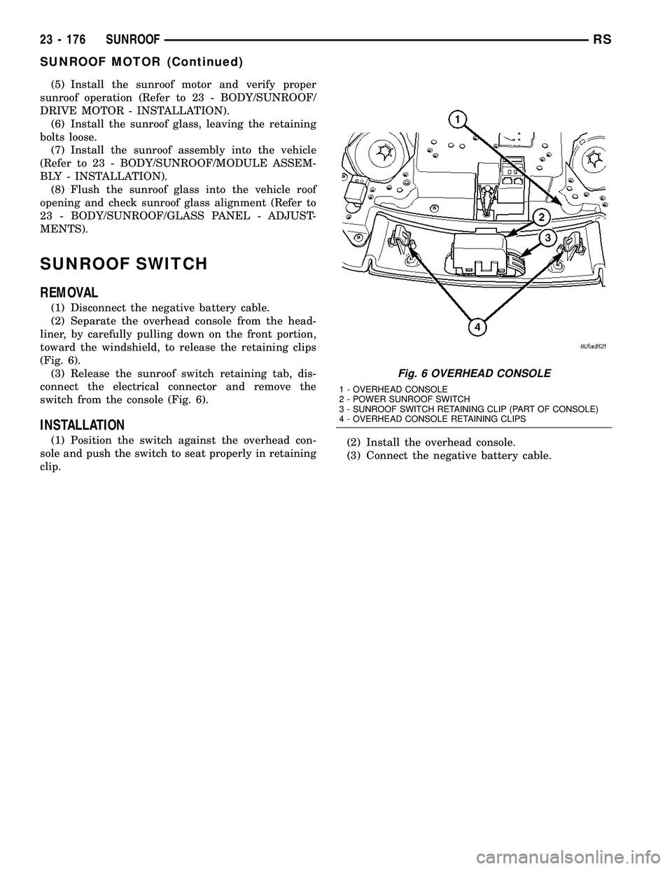
(1) Disconnect the negative battery cable.
(2) Separate the overhead console from the head-
liner, by carefully pulling down on the front portion,
toward the windshield, to release the retaining clips
(Fig. 6).
(3) Release the sunroof switch retaining tab, dis-
connect the electrical connector and remove the
switch from the console (Fig. 6).
INSTALLATION
(1) Position the switch against the overhead con-
sole and push the switch to seat properly in retaining
clip.(2) Install the overhead console.
(3) Connect the negative battery cable.
Fig. 6 OVERHEAD CONSOLE
1 - OVERHEAD CONSOLE
2 - POWER SUNROOF SWITCH
3 - SUNROOF SWITCH RETAINING CLIP (PART OF CONSOLE)
4 - OVERHEAD CONSOLE RETAINING CLIPS
23 - 176 SUNROOFRS
SUNROOF MOTOR (Continued)
Page 2165 of 2339
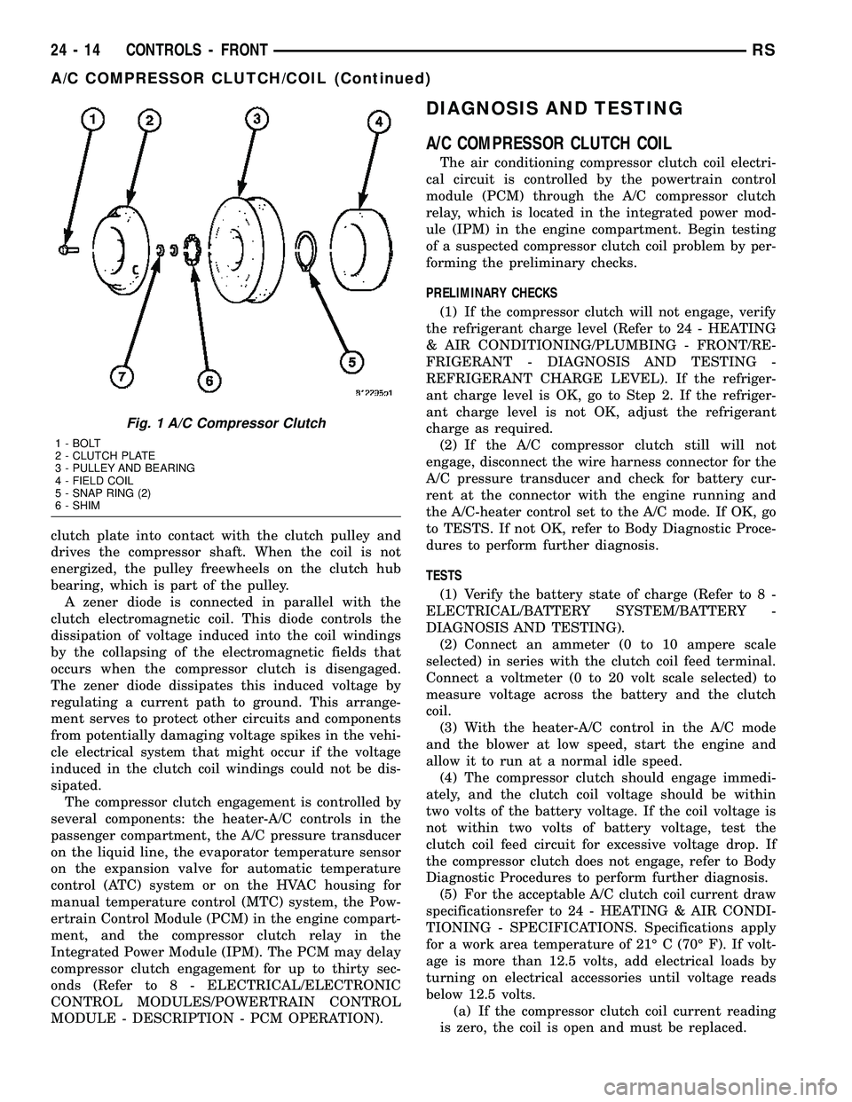
clutch plate into contact with the clutch pulley and
drives the compressor shaft. When the coil is not
energized, the pulley freewheels on the clutch hub
bearing, which is part of the pulley.
A zener diode is connected in parallel with the
clutch electromagnetic coil. This diode controls the
dissipation of voltage induced into the coil windings
by the collapsing of the electromagnetic fields that
occurs when the compressor clutch is disengaged.
The zener diode dissipates this induced voltage by
regulating a current path to ground. This arrange-
ment serves to protect other circuits and components
from potentially damaging voltage spikes in the vehi-
cle electrical system that might occur if the voltage
induced in the clutch coil windings could not be dis-
sipated.
The compressor clutch engagement is controlled by
several components: the heater-A/C controls in the
passenger compartment, the A/C pressure transducer
on the liquid line, the evaporator temperature sensor
on the expansion valve for automatic temperature
control (ATC) system or on the HVAC housing for
manual temperature control (MTC) system, the Pow-
ertrain Control Module (PCM) in the engine compart-
ment, and the compressor clutch relay in the
Integrated Power Module (IPM). The PCM may delay
compressor clutch engagement for up to thirty sec-
onds (Refer to 8 - ELECTRICAL/ELECTRONIC
CONTROL MODULES/POWERTRAIN CONTROL
MODULE - DESCRIPTION - PCM OPERATION).
DIAGNOSIS AND TESTING
A/C COMPRESSOR CLUTCH COIL
The air conditioning compressor clutch coil electri-
cal circuit is controlled by the powertrain control
module (PCM) through the A/C compressor clutch
relay, which is located in the integrated power mod-
ule (IPM) in the engine compartment. Begin testing
of a suspected compressor clutch coil problem by per-
forming the preliminary checks.
PRELIMINARY CHECKS
(1) If the compressor clutch will not engage, verify
the refrigerant charge level (Refer to 24 - HEATING
& AIR CONDITIONING/PLUMBING - FRONT/RE-
FRIGERANT - DIAGNOSIS AND TESTING -
REFRIGERANT CHARGE LEVEL). If the refriger-
ant charge level is OK, go to Step 2. If the refriger-
ant charge level is not OK, adjust the refrigerant
charge as required.
(2) If the A/C compressor clutch still will not
engage, disconnect the wire harness connector for the
A/C pressure transducer and check for battery cur-
rent at the connector with the engine running and
the A/C-heater control set to the A/C mode. If OK, go
to TESTS. If not OK, refer to Body Diagnostic Proce-
dures to perform further diagnosis.
TESTS
(1) Verify the battery state of charge (Refer to 8 -
ELECTRICAL/BATTERY SYSTEM/BATTERY -
DIAGNOSIS AND TESTING).
(2) Connect an ammeter (0 to 10 ampere scale
selected) in series with the clutch coil feed terminal.
Connect a voltmeter (0 to 20 volt scale selected) to
measure voltage across the battery and the clutch
coil.
(3) With the heater-A/C control in the A/C mode
and the blower at low speed, start the engine and
allow it to run at a normal idle speed.
(4) The compressor clutch should engage immedi-
ately, and the clutch coil voltage should be within
two volts of the battery voltage. If the coil voltage is
not within two volts of battery voltage, test the
clutch coil feed circuit for excessive voltage drop. If
the compressor clutch does not engage, refer to Body
Diagnostic Procedures to perform further diagnosis.
(5) For the acceptable A/C clutch coil current draw
specificationsrefer to 24 - HEATING & AIR CONDI-
TIONING - SPECIFICATIONS. Specifications apply
for a work area temperature of 21É C (70É F). If volt-
age is more than 12.5 volts, add electrical loads by
turning on electrical accessories until voltage reads
below 12.5 volts.
(a) If the compressor clutch coil current reading
is zero, the coil is open and must be replaced.
Fig. 1 A/C Compressor Clutch
1 - BOLT
2 - CLUTCH PLATE
3 - PULLEY AND BEARING
4 - FIELD COIL
5 - SNAP RING (2)
6 - SHIM
24 - 14 CONTROLS - FRONTRS
A/C COMPRESSOR CLUTCH/COIL (Continued)
Page 2166 of 2339
(b) If the compressor clutch coil current reading
is four amperes or more, the coil is shorted and
must be replaced.
STANDARD PROCEDURE
CLUTCH INSPECTION
NOTE: The compressor clutch can be serviced in
the vehicle. The refrigerant system can remain fully-
charged during compressor clutch, pulley, or coil
replacement.
Examine the friction surfaces of the clutch pulley
and the clutch plate for wear. The pulley and plate
should be replaced if there is excessive wear or scor-
ing.
If the friction surfaces are oily, inspect the shaft
and nose area of the A/C compressor for refrigerant
oil. If refrigerant oil is found, the compressor shaft
seal is leaking and the A/C compressor must be
replaced.
Check the clutch pulley bearing for roughness or
excessive leakage of grease. Replace the pulley and
bearing assembly, if required.
A/C CLUTCH BREAK-IN
After a new A/C compressor clutch has been
installed, cycle the compressor clutch approximately
twenty times (five seconds on, then five seconds off).
During this procedure, set the A/C-heater controls to
the A/C Recirculation Mode, the blower motor in the
highest speed position, and the engine speed at 1500
to 2000 rpm. This procedure (burnishing) will seat
the opposing friction surfaces of the compressor
clutch, which provides optimum compressor clutch
torque capability.
REMOVAL
NOTE: The compressor clutch can be serviced in
the vehicle. The refrigerant system can remain fully-
charged during compressor clutch, pulley, or coil
replacement.
(1) Disconnect and isolate the negative battery
cable.
(2) Remove the accessory drive belt (Refer to 7 -
COOLING/ACCESSORY DRIVE/DRIVE BELTS -
REMOVAL).
(3) Raise and support the vehicle.
(4) Disconnect the engine wire harness connector
for the compressor clutch coil from the clutch coil pig-
tail wire connector on the top of the A/C compressor.
(5) On models with the 3.3L and 3.8L engines, dis-
engage the retainer on the engine wire harness com-pressor clutch coil take out from the bracket on the
top of the A/C compressor.
(6) On models with the 2.4L, 2.5L and 2.8L
engines, remove all of the compressor mounting bolts
except the upper left (rear of the A/C compressor),
which should only be loosened. Allow the front (pul-
ley end) of the A/C compressor to tilt downward far
enough to access the clutch for removal, then tighten
the loosened upper left compressor mounting bolt.
(7) On models with the 3.3L and 3.8L engines,
remove the two bolts and two nuts that secure the
A/C compressor to the engine. Disengage the mount-
ing ear at the front of the A/C compressor from the
stud on the engine, allow the front (pulley end) of the
A/C compressor to tilt downward far enough to access
the clutch for removal, then reinstall and tighten the
upper left compressor mounting bolt.
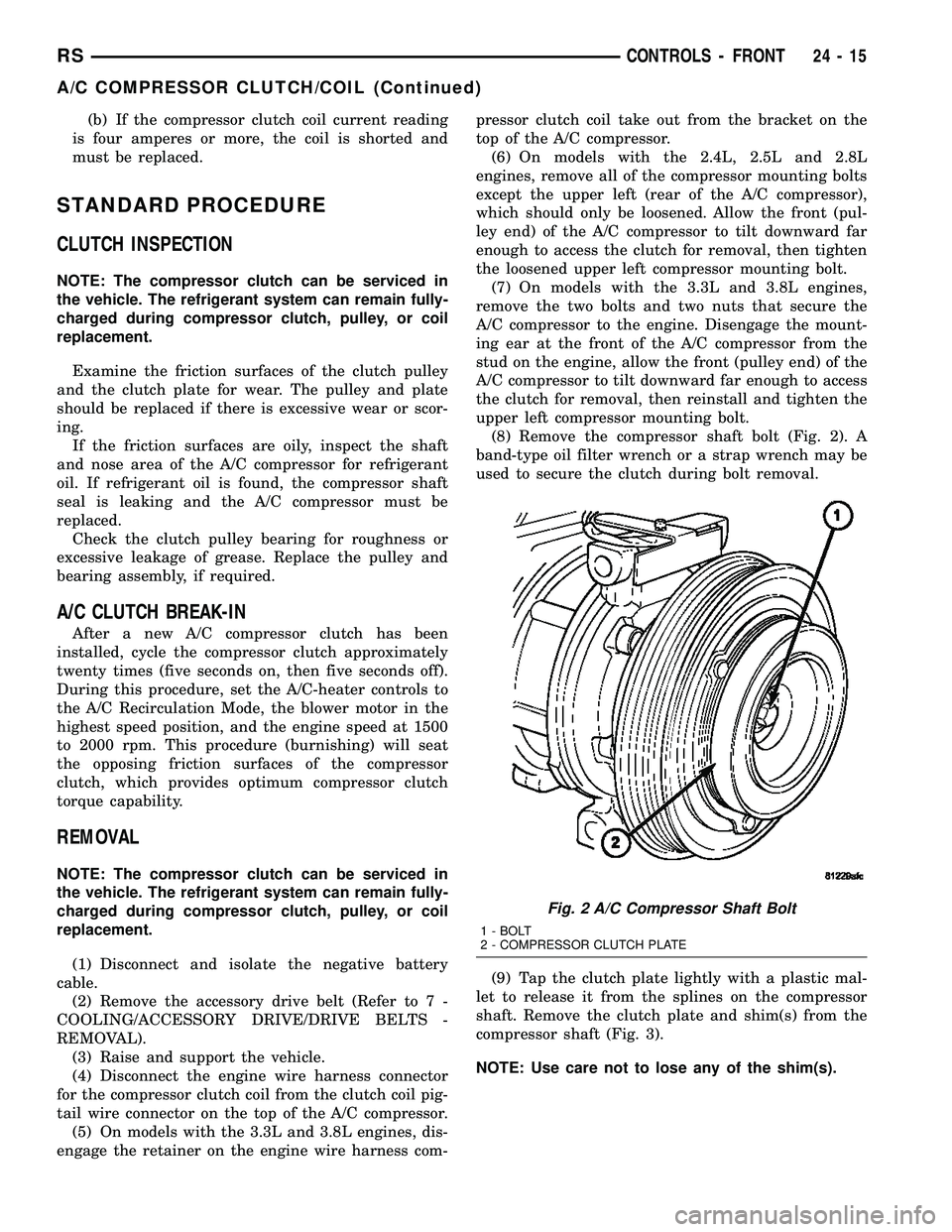
(8) Remove the compressor shaft bolt (Fig. 2). A
band-type oil filter wrench or a strap wrench may be
used to secure the clutch during bolt removal.
(9) Tap the clutch plate lightly with a plastic mal-
let to release it from the splines on the compressor
shaft. Remove the clutch plate and shim(s) from the
compressor shaft (Fig. 3).
NOTE: Use care not to lose any of the shim(s).
Fig. 2 A/C Compressor Shaft Bolt
1 - BOLT
2 - COMPRESSOR CLUTCH PLATE
RSCONTROLS - FRONT24-15
A/C COMPRESSOR CLUTCH/COIL (Continued)
Page 2168 of 2339
compressor. The bevel side of the snap ring must face
outward and both snap ring eyelets must be oriented
to the right or the left of the clutch coil dowel pin
location on the A/C compressor. Be certain that the
snap ring is fully and properly seated in the groove.
CAUTION: If the snap ring is not fully seated in the
groove it will vibrate out, resulting in a clutch fail-
ure and severe damage to the compressor front
cover.
(3) Install and securely tighten the screw that
secures the clutch coil pigtail wire connector bracket
and ground clip to the top of the compressor housing.
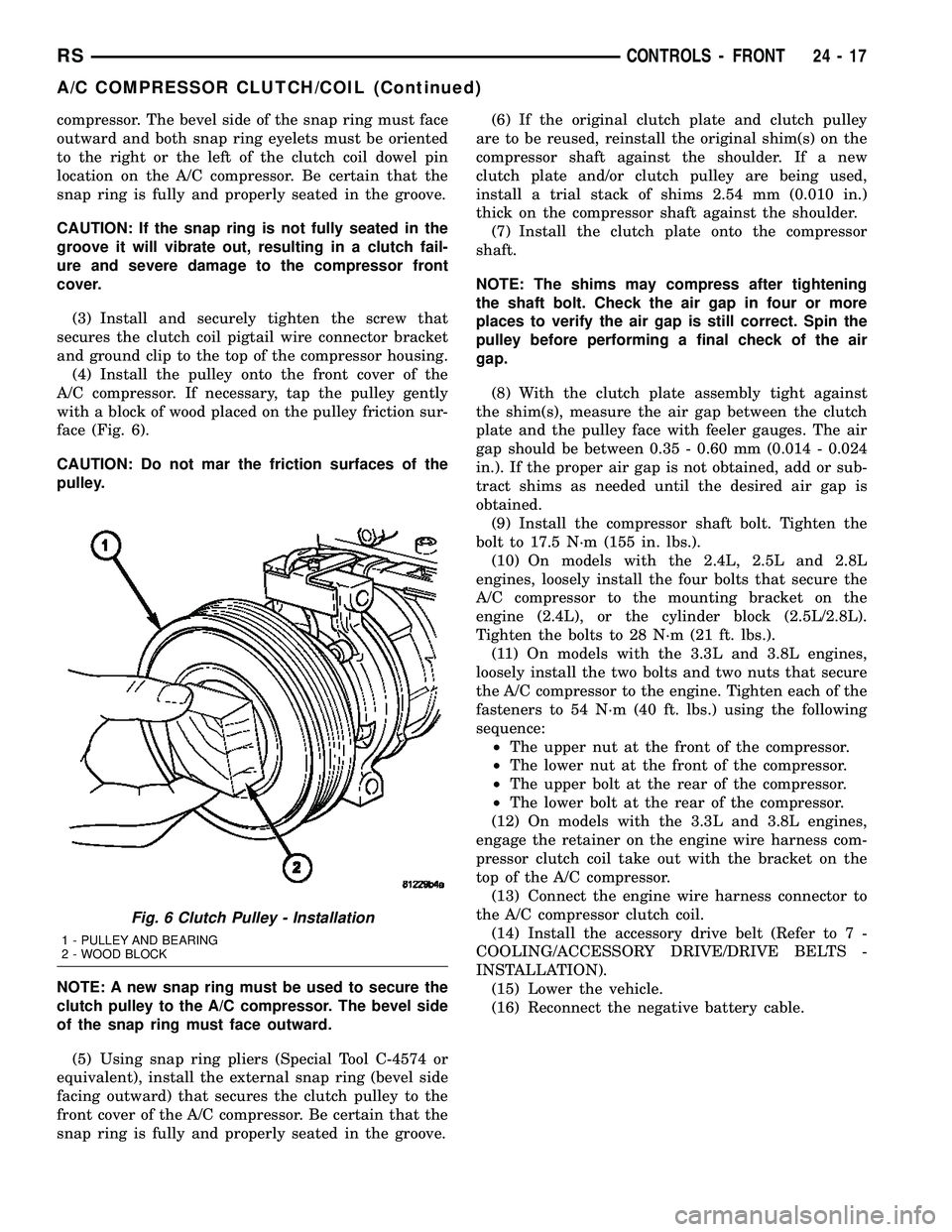
(4) Install the pulley onto the front cover of the
A/C compressor. If necessary, tap the pulley gently
with a block of wood placed on the pulley friction sur-
face (Fig. 6).
CAUTION: Do not mar the friction surfaces of the
pulley.
NOTE: A new snap ring must be used to secure the
clutch pulley to the A/C compressor. The bevel side
of the snap ring must face outward.
(5) Using snap ring pliers (Special Tool C-4574 or
equivalent), install the external snap ring (bevel side
facing outward) that secures the clutch pulley to the
front cover of the A/C compressor. Be certain that the
snap ring is fully and properly seated in the groove.(6) If the original clutch plate and clutch pulley
are to be reused, reinstall the original shim(s) on the
compressor shaft against the shoulder. If a new
clutch plate and/or clutch pulley are being used,
install a trial stack of shims 2.54 mm (0.010 in.)
thick on the compressor shaft against the shoulder.
(7) Install the clutch plate onto the compressor
shaft.
NOTE: The shims may compress after tightening
the shaft bolt. Check the air gap in four or more
places to verify the air gap is still correct. Spin the
pulley before performing a final check of the air
gap.
(8) With the clutch plate assembly tight against
the shim(s), measure the air gap between the clutch
plate and the pulley face with feeler gauges. The air
gap should be between 0.35 - 0.60 mm (0.014 - 0.024
in.). If the proper air gap is not obtained, add or sub-
tract shims as needed until the desired air gap is
obtained.
(9) Install the compressor shaft bolt. Tighten the
bolt to 17.5 N´m (155 in. lbs.).
(10) On models with the 2.4L, 2.5L and 2.8L
engines, loosely install the four bolts that secure the
A/C compressor to the mounting bracket on the
engine (2.4L), or the cylinder block (2.5L/2.8L).
Tighten the bolts to 28 N´m (21 ft. lbs.).
(11) On models with the 3.3L and 3.8L engines,
loosely install the two bolts and two nuts that secure
the A/C compressor to the engine. Tighten each of the
fasteners to 54 N´m (40 ft. lbs.) using the following
sequence:
²The upper nut at the front of the compressor.
²The lower nut at the front of the compressor.
²The upper bolt at the rear of the compressor.
²The lower bolt at the rear of the compressor.
(12) On models with the 3.3L and 3.8L engines,
engage the retainer on the engine wire harness com-
pressor clutch coil take out with the bracket on the
top of the A/C compressor.
(13) Connect the engine wire harness connector to
the A/C compressor clutch coil.
(14) Install the accessory drive belt (Refer to 7 -
COOLING/ACCESSORY DRIVE/DRIVE BELTS -
INSTALLATION).
(15) Lower the vehicle.
(16) Reconnect the negative battery cable.
Fig. 6 Clutch Pulley - Installation
1 - PULLEY AND BEARING
2 - WOOD BLOCK
RSCONTROLS - FRONT24-17
A/C COMPRESSOR CLUTCH/COIL (Continued)