2005 CHRYSLER CARAVAN horn
[x] Cancel search: hornPage 1051 of 2339
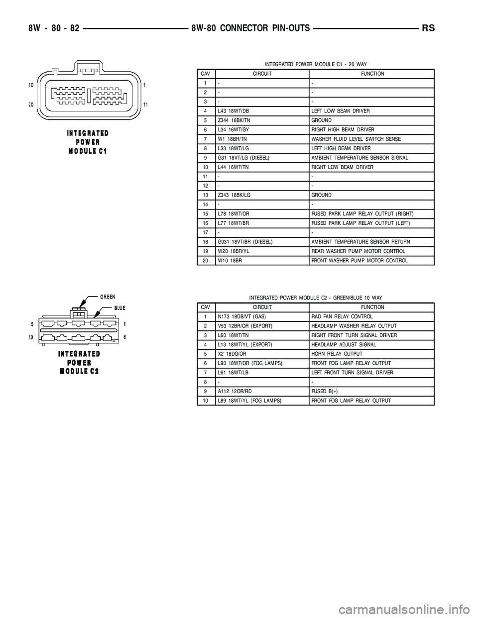
INTEGRATED POWER MODULE C1 - 20 WAY
CAV CIRCUIT FUNCTION
1- -
2- -
3- -
4 L43 18WT/DB LEFT LOW BEAM DRIVER
5 Z344 16BK/TN GROUND
6 L34 16WT/GY RIGHT HIGH BEAM DRIVER
7 W1 18BR/TN WASHER FLUID LEVEL SWITCH SENSE
8 L33 18WT/LG LEFT HIGH BEAM DRIVER
9 G31 18VT/LG (DIESEL) AMBIENT TEMPERATURE SENSOR SIGNAL
10 L44 16WT/TN RIGHT LOW BEAM DRIVER
11 - -
12 - -
13 Z343 18BK/LG GROUND
14 - -
15 L78 18WT/OR FUSED PARK LAMP RELAY OUTPUT (RIGHT)
16 L77 18WT/BR FUSED PARK LAMP RELAY OUTPUT (LEFT)
17 - -
18 G931 18VT/BR (DIESEL) AMBIENT TEMPERATURE SENSOR RETURN
19 W20 18BR/YL REAR WASHER PUMP MOTOR CONTROL
20 W10 18BR FRONT WASHER PUMP MOTOR CONTROL
INTEGRATED POWER MODULE C2 - GREEN/BLUE 10 WAY
CAV CIRCUIT FUNCTION
1 N173 18DB/VT (GAS) RAD FAN RELAY CONTROL
2 V53 12BR/OR (EXPORT) HEADLAMP WASHER RELAY OUTPUT
3 L60 18WT/TN RIGHT FRONT TURN SIGNAL DRIVER
4 L13 18WT/YL (EXPORT) HEADLAMP ADJUST SIGNAL
5 X2 18DG/OR HORN RELAY OUTPUT
6 L90 18WT/OR (FOG LAMPS) FRONT FOG LAMP RELAY OUTPUT
7 L61 18WT/LB LEFT FRONT TURN SIGNAL DRIVER
8- -
9 A112 12OR/RD FUSED B(+)
10 L89 18WT/YL (FOG LAMPS) FRONT FOG LAMP RELAY OUTPUT
8W - 80 - 82 8W-80 CONNECTOR PIN-OUTSRS
Page 1053 of 2339
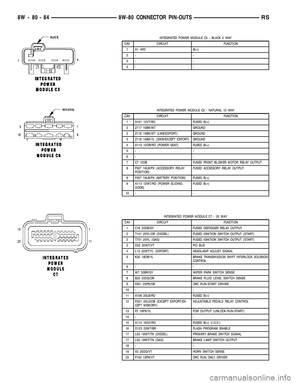
INTEGRATED POWER MODULE C5 - BLACK 4 WAY
CAV CIRCUIT FUNCTION
1 A1 4RD B(+)
2- -
3- -
4- -
INTEGRATED POWER MODULE C6 - NATURAL 10 WAY
CAV CIRCUIT FUNCTION
1 A101 12VT/RD FUSED B(+)
2 Z117 16BK/WT GROUND
3 Z118 16BK/WT (LWB/EXPORT) GROUND
3 Z118 16BK/YL (SWB/EXCEPT EXPORT) GROUND
4 A110 12OR/RD (POWER SEAT) FUSED B(+)
5- -
6- -
7 C7 12DB FUSED FRONT BLOWER MOTOR RELAY OUTPUT
8 F307 18LB/PK (ACCESSORY RELAY
POSITION)FUSED ACCESSORY RELAY OUTPUT
8 F307 18LB/PK (BATTERY POSITION) FUSED B(+)
9 A113 12WT/RD (POWER SLIDING
DOOR)FUSED B(+)
10 - -
INTEGRATED POWER MODULE C7 - 20 WAY
CAV CIRCUIT FUNCTION
1 C16 20DB/GY FUSED DEFOGGER RELAY OUTPUT
2 T141 20YL/OR (DIESEL) FUSED IGNITION SWITCH OUTPUT (START)
2 T751 20YL (GAS) FUSED IGNITION SWITCH OUTPUT (START)
3 D25 20WT/VT PCI BUS
4 L13 20WT/YL (EXPORT) HEADLAMP ADJUST SIGNAL
5 K32 18DB/YL BRAKE TRANSMISSION SHIFT INTERLOCK SOLENOID
CONTROL
6- -
7 W7 20BR/GY WIPER PARK SWITCH SENSE
8 B20 20DG/OR BRAKE FLUID LEVEL SWITCH SENSE
9 F201 20PK/OR ORC RUN-START DRIVER
10 - -
11 A106 20LB/RD FUSED B(+)
12 P201 20LG/DB (EXCEPT EXPORT/EX-
CEPT MEMORY)ADJUSTABLE PEDALS RELAY CONTROL
13 F2 18PK/YL FCM OUTPUT (UNLOCK-RUN-START)
14 - -
15 A114 16GY/RD FUSED B(+) (I.O.D.)
16 D123 20WT/BR FLASH PROGRAM ENABLE
17 L50 18WT/TN (DIESEL) PRIMARY BRAKE SWITCH SIGNAL
17 L50 18WT/TN (GAS) BRAKE LAMP SWITCH OUTPUT
18 - -
19 X3 20DG/VT HORN SWITCH SENSE
20 F100 18PK/VT ORC RUN ONLY DRIVER
8W - 80 - 84 8W-80 CONNECTOR PIN-OUTSRS
Page 1119 of 2339
CONNECTOR NAME/NUMBER COLOR LOCATION FIG.
Hands Free Module C2 BK Instrument Panel N/S
Hands Free Module C3 Instrument Panel N/S
Headlamp Switch BK Rear of Switch 20, 21, 30
Headlamp Washer Pump Motor
(Export)BK At Motor 3
High Note Horn BK Left Frame Rail 5
Hood Ajar Switch (Export) BK Left Fender 6
Idle Air Control Motor (Gas) BK On Throttle Body 10, 11 17
Ignition Coil (2.4L) BK Top of Valve Cover 10, 11
Ignition Coil (3.3L/ 3.8L) DKGY Top of Engine 17, 18
Ignition Switch BK Rear of Switch at Steering Column 20, 21, 22, 23, 31
Inlet Air Temperature Sensor BK Top Left of Engine 9, 10, 11, 17
Input Speed Sensor GY Front of Transmission 14, 19
Instrument Cluster BK Rear of Cluster 20, 21, 28
Instrument Panel Switch Bank
(Heated Seats)BK Right Center of Instrument Panel 20, 23, 25
Instrument Panel Switch Bank
(Except Heated Seats)Right Center of Instrument Panel 20, 23, 25
Integrated Power Module C1 Left Fender Shield 7
Integrated Power Module C2 GN/BL Left Fender Shield 7
Integrated Power Module C3 Left Fender Shield 7, 11
Integrated Power Module C4 BL Left Fender Shield 7, 11
Integrated Power Module C5 BK Left Fender Shield 7
Integrated Power Module C6 NAT Left Fender Shield 7
Integrated Power Module C7 Left Fender Shield 7
Integrated Power Module C8 OR Left Fender Shield 7
Integrated Power Module C9 BK Left Fender Shield 7
Knock Sensor (Except Export) BK At Engine Block 11
Left B Pillar Switch (Power
Sliding Door)GY Left B Pillar 40
Left Cinch/Release Motor (Power
Sliding Door)GY Left Sliding Door N/S
Left Curtain Airbag Squib Rear of Left Roof Rail 47
Left Cylinder Lock Switch BK At Switch 43
Left Door Speaker BK At Speaker 43
Left Fog Lamp BK At Lamp 5
Left Front Door Ajar Switch
(Base)BK At Switch N/S
Left Front Door Lock Motor/Ajar
Switch (Except Base)BK Left Door 43
Left Front Impact Sensor BK Near T/O for C101 5
Left Front Park/Turn Signal Lamp
(Except Export)DKGY At Lamp 1
Left Front Wheel Speed Sensor GY Left Fender Side Shield 5, 11
8W - 91 - 6 8W-91 CONNECTOR/GROUND/SPLICE LOCATIONRS
CONNECTOR/GROUND/SPLICE LOCATION (Continued)
Page 1418 of 2339
WARNING: THE AIR BAG SYSTEM IS A SENSITIVE,
COMPLEX ELECTRO-MECHANICAL UNIT. BEFORE
ATTEMPTING TO DIAGNOSE, REMOVE OR INSTALL
THE AIR BAG SYSTEM COMPONENTS YOU MUST
FIRST DISCONNECT AND ISOLATE THE BATTERY
NEGATIVE (GROUND) CABLE. THEN WAIT TWO
MINUTES FOR THE SYSTEM CAPACITOR TO DIS-
CHARGE. FAILURE TO DO SO COULD RESULT IN
ACCIDENTAL DEPLOYMENT OF THE AIR BAG AND
POSSIBLE PERSONAL INJURY. THE FASTENERS,
SCREWS, AND BOLTS, ORIGINALLY USED FOR
THE AIR BAG COMPONENTS, HAVE SPECIAL
COATINGS AND ARE SPECIFICALLY DESIGNED
FOR THE AIR BAG SYSTEM. THEY MUST NEVER
BE REPLACED WITH ANY SUBSTITUTES. ANYTIME
A NEW FASTENER IS NEEDED, REPLACE WITH
THE CORRECT FASTENERS PROVIDED IN THE
SERVICE PACKAGE OR FASTENERS LISTED IN
THE PARTS BOOKS.
WARNING: SAFETY GOGGLES SHOULD BE WORN
AT ALL TIMES WHEN WORKING ON STEERING
COLUMNS.
CAUTION: Disconnect negative (ground) cable from
the battery before servicing any column compo-
nent.
CAUTION: Do not attempt to remove the pivot pins
to disassemble the tilting mechanism. Damage will
occur.
DIAGNOSIS AND TESTING - STEERING
COLUMN
For diagnosis of conditions relating to the steering
column, (Refer to 19 - STEERING - DIAGNOSIS
AND TESTING).
REMOVAL
NOTE: Before proceeding, (Refer to 19 - STEERING/
COLUMN - WARNING)(Refer to 8 - ELECTRICAL/RE-
STRAINTS/DRIVER AIRBAG - REMOVAL).
(1) Make sure the front wheels of the vehicle are
in the STRAIGHT AHEAD position before beginning
the column removal procedure.
(2) Disconnect and isolate the negative (ground)
cable from the battery. Wait at least two minutes for
the airbag system reserve capacitor to discharge
before beginning any steering column, instrument
panel, or airbag system/component service.WARNING: WHEN AN UNDEPLOYED AIRBAG IS TO
BE REMOVED FROM THE VEHICLE, FIRST DISCON-
NECT AND ISOLATE THE BATTERY NEGATIVE
(GROUND) CABLE. ALLOW THE AIRBAG SYSTEM
RESERVE CAPACITOR TO DISCHARGE FOR TWO
MINUTES BEFORE BEGINNING ANY AIRBAG SYS-
TEM OR COMPONENT SERVICE. PERSONAL
INJURY MAY RESULT IF THIS PROCEDURE IS NOT
FOLLOWED.
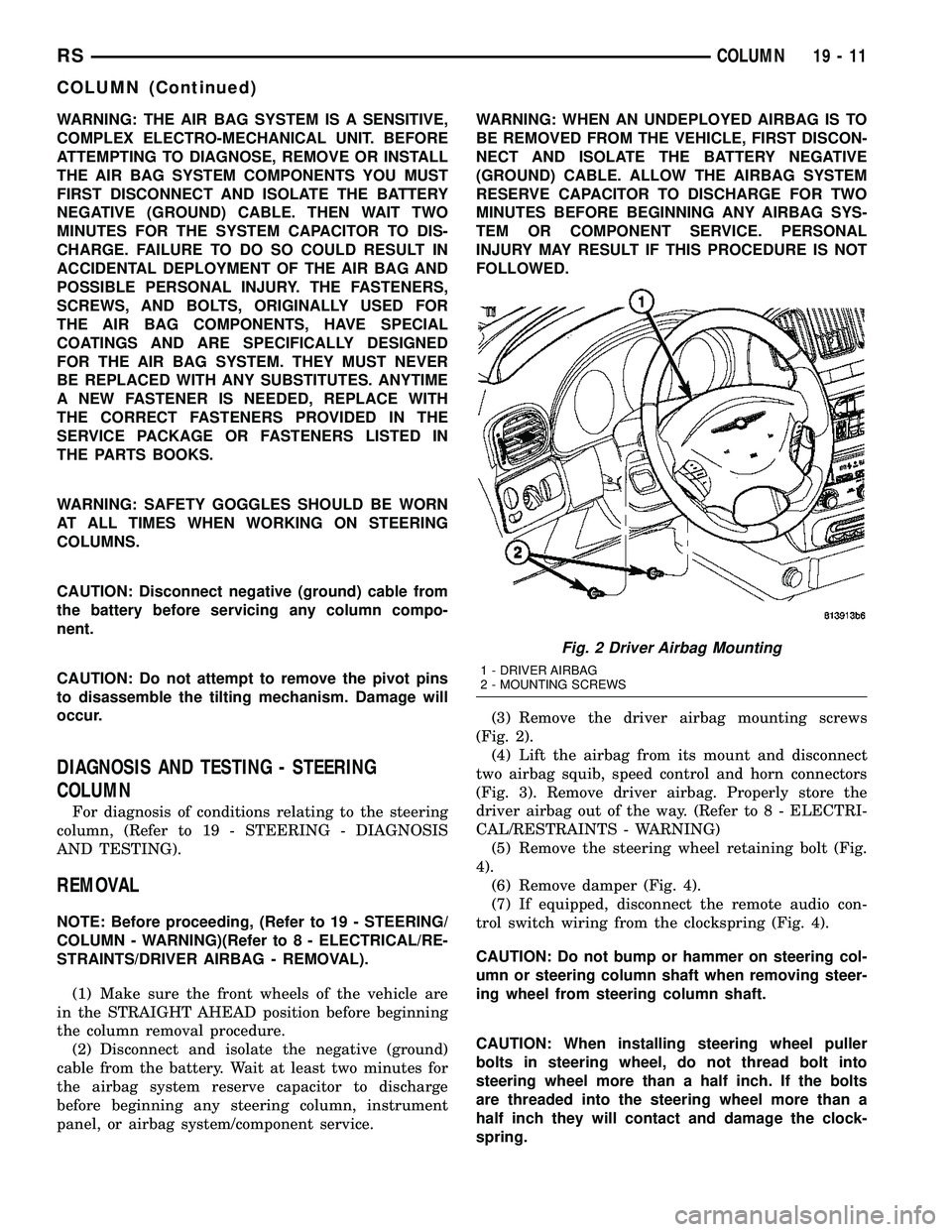
(3) Remove the driver airbag mounting screws
(Fig. 2).
(4) Lift the airbag from its mount and disconnect
two airbag squib, speed control and horn connectors
(Fig. 3). Remove driver airbag. Properly store the
driver airbag out of the way. (Refer to 8 - ELECTRI-
CAL/RESTRAINTS - WARNING)
(5) Remove the steering wheel retaining bolt (Fig.
4).
(6) Remove damper (Fig. 4).
(7) If equipped, disconnect the remote audio con-
trol switch wiring from the clockspring (Fig. 4).
CAUTION: Do not bump or hammer on steering col-
umn or steering column shaft when removing steer-
ing wheel from steering column shaft.
CAUTION: When installing steering wheel puller
bolts in steering wheel, do not thread bolt into
steering wheel more than a half inch. If the bolts
are threaded into the steering wheel more than a
half inch they will contact and damage the clock-
spring.
Fig. 2 Driver Airbag Mounting
1 - DRIVER AIRBAG
2 - MOUNTING SCREWS
RSCOLUMN19-11
COLUMN (Continued)
Page 1419 of 2339
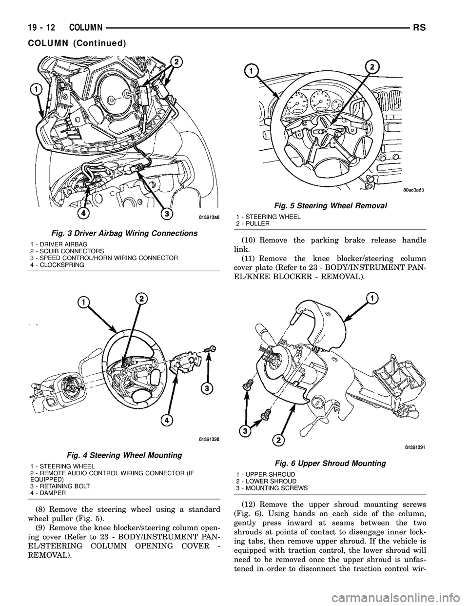
(8) Remove the steering wheel using a standard
wheel puller (Fig. 5).
(9) Remove the knee blocker/steering column open-
ing cover (Refer to 23 - BODY/INSTRUMENT PAN-
EL/STEERING COLUMN OPENING COVER -
REMOVAL).(10) Remove the parking brake release handle
link.
(11) Remove the knee blocker/steering column
cover plate (Refer to 23 - BODY/INSTRUMENT PAN-
EL/KNEE BLOCKER - REMOVAL).
(12) Remove the upper shroud mounting screws
(Fig. 6). Using hands on each side of the column,
gently press inward at seams between the two
shrouds at points of contact to disengage inner lock-
ing tabs, then remove upper shroud. If the vehicle is
equipped with traction control, the lower shroud will
need to be removed once the upper shroud is unfas-
tened in order to disconnect the traction control wir-
Fig. 3 Driver Airbag Wiring Connections
1 - DRIVER AIRBAG
2 - SQUIB CONNECTORS
3 - SPEED CONTROL/HORN WIRING CONNECTOR
4 - CLOCKSPRING
Fig. 4 Steering Wheel Mounting
1 - STEERING WHEEL
2 - REMOTE AUDIO CONTROL WIRING CONNECTOR (IF
EQUIPPED)
3 - RETAINING BOLT
4 - DAMPER
Fig. 5 Steering Wheel Removal
1 - STEERING WHEEL
2 - PULLER
Fig. 6 Upper Shroud Mounting
1 - UPPER SHROUD
2 - LOWER SHROUD
3 - MOUNTING SCREWS
19 - 12 COLUMNRS
COLUMN (Continued)
Page 1421 of 2339
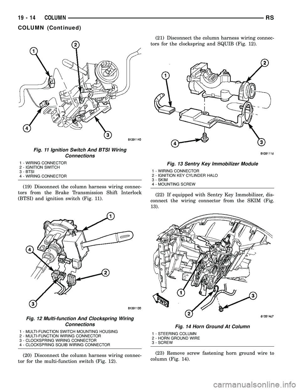
(19) Disconnect the column harness wiring connec-
tors from the Brake Transmission Shift Interlock
(BTSI) and ignition switch (Fig. 11).
(20) Disconnect the column harness wiring connec-
tor for the multi-function switch (Fig. 12).(21) Disconnect the column harness wiring connec-
tors for the clockspring and SQUIB (Fig. 12).
(22) If equipped with Sentry Key Immobilizer, dis-
connect the wiring connector from the SKIM (Fig.
13).
(23) Remove screw fastening horn ground wire to
column (Fig. 14).
Fig. 11 Ignition Switch And BTSI Wiring
Connections
1 - WIRING CONNECTOR
2 - IGNITION SWITCH
3 - BTSI
4 - WIRING CONNECTOR
Fig. 12 Multi-function And Clockspring Wiring
Connections
1 - MULTI-FUNCTION SWITCH MOUNTING HOUSING
2 - MULTI-FUNCTION WIRING CONNECTOR
3 - CLOCKSPRING WIRING CONNECTOR
4 - CLOCKSPRING SQUIB WIRING CONNECTOR
Fig. 13 Sentry Key Immobilizer Module
1 - WIRING CONNECTOR
2 - IGNITION KEY CYLINDER HALO
3 - SKIM
4 - MOUNTING SCREW
Fig. 14 Horn Ground At Column
1 - STEERING COLUMN
2 - HORN GROUND WIRE
3 - SCREW
19 - 14 COLUMNRS
COLUMN (Continued)
Page 1423 of 2339
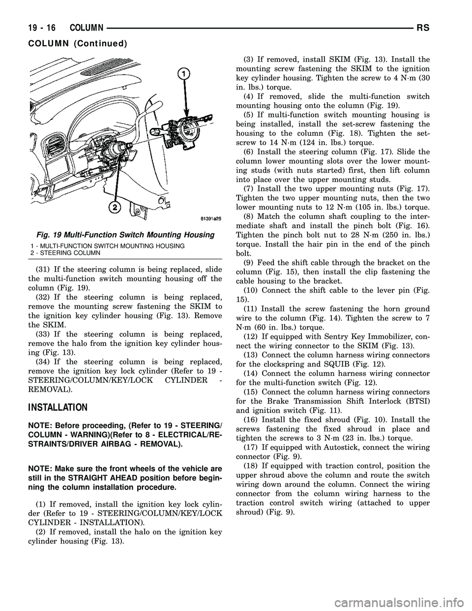
(31) If the steering column is being replaced, slide
the multi-function switch mounting housing off the
column (Fig. 19).
(32) If the steering column is being replaced,
remove the mounting screw fastening the SKIM to
the ignition key cylinder housing (Fig. 13). Remove
the SKIM.
(33) If the steering column is being replaced,
remove the halo from the ignition key cylinder hous-
ing (Fig. 13).
(34) If the steering column is being replaced,
remove the ignition key lock cylinder (Refer to 19 -
STEERING/COLUMN/KEY/LOCK CYLINDER -
REMOVAL).
INSTALLATION
NOTE: Before proceeding, (Refer to 19 - STEERING/
COLUMN - WARNING)(Refer to 8 - ELECTRICAL/RE-
STRAINTS/DRIVER AIRBAG - REMOVAL).
NOTE: Make sure the front wheels of the vehicle are
still in the STRAIGHT AHEAD position before begin-
ning the column installation procedure.
(1) If removed, install the ignition key lock cylin-
der (Refer to 19 - STEERING/COLUMN/KEY/LOCK
CYLINDER - INSTALLATION).
(2) If removed, install the halo on the ignition key
cylinder housing (Fig. 13).(3) If removed, install SKIM (Fig. 13). Install the
mounting screw fastening the SKIM to the ignition
key cylinder housing. Tighten the screw to 4 N´m (30
in. lbs.) torque.
(4) If removed, slide the multi-function switch
mounting housing onto the column (Fig. 19).
(5) If multi-function switch mounting housing is
being installed, install the set-screw fastening the
housing to the column (Fig. 18). Tighten the set-
screw to 14 N´m (124 in. lbs.) torque.
(6) Install the steering column (Fig. 17). Slide the
column lower mounting slots over the lower mount-
ing studs (with nuts started) first, then lift column
into place over the upper mounting studs.
(7) Install the two upper mounting nuts (Fig. 17).
Tighten the two upper mounting nuts, then the two
lower mounting nuts to 12 N´m (105 in. lbs.) torque.
(8) Match the column shaft coupling to the inter-
mediate shaft and install the pinch bolt (Fig. 16).
Tighten the pinch bolt nut to 28 N´m (250 in. lbs.)
torque. Install the hair pin in the end of the pinch
bolt.
(9) Feed the shift cable through the bracket on the
column (Fig. 15), then install the clip fastening the
cable housing to the bracket.
(10) Connect the shift cable to the lever pin (Fig.
15).
(11) Install the screw fastening the horn ground
wire to the column (Fig. 14). Tighten the screw to 7
N´m (60 in. lbs.) torque.
(12) If equipped with Sentry Key Immobilizer, con-
nect the wiring connector to the SKIM (Fig. 13).
(13) Connect the column harness wiring connectors
for the clockspring and SQUIB (Fig. 12).
(14) Connect the column harness wiring connector
for the multi-function switch (Fig. 12).
(15) Connect the column harness wiring connectors
for the Brake Transmission Shift Interlock (BTSI)
and ignition switch (Fig. 11).
(16) Install the fixed shroud (Fig. 10). Install the
screws fastening the fixed shroud in place and
tighten the screws to 3 N´m (23 in. lbs.) torque.
(17) If equipped with Autostick, connect the wiring
connector (Fig. 9).
(18) If equipped with traction control, position the
upper shroud above the column and route the switch
wiring down around the column. Connect the wiring
connector from the column wiring harness to the
traction control switch wiring (attached to upper
shroud) (Fig. 9).
Fig. 19 Multi-Function Switch Mounting Housing
1 - MULTI-FUNCTION SWITCH MOUNTING HOUSING
2 - STEERING COLUMN
19 - 16 COLUMNRS
COLUMN (Continued)
Page 1424 of 2339

(19) Position the lower shroud on the column (Fig.
8). Install the lower shroud mounting screw. Tighten
the screw to 2 N´m (17 in. lbs.) torque.
(20) If equipped with adjustable pedals, Connect
the wiring connector for the switch (Fig. 7) to the col-
umn wiring harness.
(21) Position the upper shroud on top of the lower
shroud and snap it into place. Install the upper
shroud mounting screws (Fig. 6). Tighten the screws
to 2 N´m (17 in. lbs.) torque.
(22) Inspect shroud mating surfaces for excessive
gaps and correct as necessary.
(23) Install the cluster trim bezel (Refer to 23 -
BODY/INSTRUMENT PANEL/CLUSTER BEZEL -
INSTALLATION).
(24) Install the knee blocker/steering column cover
plate. (Refer to 23 - BODY/INSTRUMENT PANEL/
KNEE BLOCKER - INSTALLATION)
(25) Install the parking brake handle link.
(26) Install the knee blocker/steering column open-
ing cover. (Refer to 23 - BODY/INSTRUMENT PAN-
EL/STEERING COLUMN OPENING COVER -
INSTALLATION)
(27) Align the splines and install the steering
wheel on the steering column shaft(Refer to 19 -
STEERING/COLUMN/STEERING WHEEL -
INSTALLATION).
(28) Install the damper over the steering column
shaft (Fig. 4).
(29) Install the steering wheel retaining bolt (Fig.
4). Tighten the bolt to 61 N´m (45 ft. lbs.) torque.
(30) If the steering wheel is equipped with remote
audio controls, connect the wiring connector to the
clockspring (Fig. 4).
(31) Connect the two squib connectors to the
driver airbag (Fig. 3). The connectors are color coded
to avoid connector mix-up.
(32) Connect the speed control and horn connector
to the clockspring (Fig. 3).
(33) Install the airbag to the steering wheel.
Install the driver airbag mounting screws (Fig. 2).
Tighten screws to 10 N´m (90 in. lbs.) torque.
(34) Connect the battery negative (ground) cable to
battery post following special Diagnosis And Testing
procedure. (Refer to 8 - ELECTRICAL/RESTRAINTS
- DIAGNOSIS AND TESTING)
(35) Check operation of all steering column
mounted components.
(36) Road test vehicle to ensure proper operation
of steering.SPECIFICATIONS
COLUMN FASTENER TORQUE
DESCRIPTION N´mFt.
Lbs.In.
Lbs.
Driver Airbag Mounting Screws 10 Ð 90
Multi-Function Switch Mounting
Housing Set-Screw14 Ð 124
Shroud Attaching Screws - Fixed 3 Ð 23
Shroud Attaching Screws -
Lower/Upper2Ð17
SKIM Attaching Screw 4 Ð 30
Steering Column Coupling Pinch
Bolt28 Ð 250
Steering Column Mounting Nuts 12 Ð 105
Steering Wheel Retaining Bolt 61 45 Ð
IGNITION SWITCH
REMOVAL
The ignition switch attaches to the lock cylinder
housing on the end opposite the lock cylinder (Fig.
20). For ignition switch terminal and circuit identifi-
cation, refer to the appropriate wiring information.
The wiring information includes wiring diagrams,
proper wire and connector repair procedures, further
details on wire harness routing and retention, as well
as pin-out and location views for the various wire
harness connectors, splices and grounds.
(1) Disconnect negative cable from battery.
Fig. 20 Ignition SwitchÐViewed From Below
Column
1 - IGNITION SWITCH
2 - LOCK CYLINDER HOUSING
3 - RETAINING TABS
RSCOLUMN19-17
COLUMN (Continued)