2005 CHRYSLER CARAVAN charging
[x] Cancel search: chargingPage 571 of 2339

DESCRIPTION - CIRCUIT FUNCTIONS
All circuits in the diagrams use an alpha/numeric
code to identify the wire and it's function. To identify
which circuit code applies to a system, refer to the
Circuit Identification Code Chart. This chart shows
the main circuits only and does not show the second-
ary codes that may apply to some models.
CIRCUIT IDENTIFICATION CODE CHART
CIRCUIT FUNCTION
A BATTERY FEED
B BRAKE CONTROLS
C CLIMATE CONTROLS
D DIAGNOSTIC CIRCUITS
E DIMMING ILLUMINATION
CIRCUITS
F FUSED CIRCUITS
G MONITORING CIRCUITS
(GAUGES)
H MULTIPLE
I NOT USED
J OPEN
K POWERTRAIN CONTROL
MODULE
L EXTERIOR LIGHTING
M INTERIOR LIGHTING
N MULTIPLE
O NOT USED
P POWER OPTION (BATTERY
FEED)
Q POWER OPTIONS (IGNITION
FEED)
R PASSIVE RESTRAINT
S SUSPENSION/STEERING
T TRANSMISSION/TRANSAXLE/
TRANSFER CASE
U OPEN
V SPEED CONTROL, WIPER/
WASHER
W WIPERS
X AUDIO SYSTEMS
Y TEMPORARY
Z GROUNDS
DESCRIPTION - SECTION IDENTIFICATION AND
INFORMATION
The wiring diagrams are grouped into individual
sections. If a component is most likely found in a par-
ticular group, it will be shown complete (all wires,
connectors, and pins) within that group. For exam-
ple, the Auto Shutdown Relay is most likely to be
found in Group 30, so it is shown there complete. It
can, however, be shown partially in another group if
it contains some associated wiring.
Splice diagrams in Section 8W-70 show the entire
splice and provide references to other sections the
splices serves. Section 8W-70 only contains splice dia-
grams that are not shown in their entirety some-
where else in the wiring diagrams.
Section 8W-80 shows each connector and the cir-
cuits involved with that connector. The connectors
are identified using the name/number on the dia-
gram pages.
WIRING SECTION CHART
GROUP TOPIC
8W-01 thru
8W-09General information and Diagram
Overview
8W-10 thru
8W-19Main Sources of Power and
Vehicle Grounding
8W-20 thru
8W-29Starting and Charging
8W-30 thru
8W-39Powertrain/Drivetrain Systems
8W-40 thru
8W-49Body Electrical items and A/C
8W-50 thru
8W-59Exterior Lighting, Wipers and
Trailer Tow
8W-60 thru
8W-69Power Accessories
8W-70 Splice Information
8W-80 Connector Pin Outs
8W-91 Connector, Ground and Splice
Locations
8W - 01 - 6 8W-01 WIRING DIAGRAM INFORMATIONRS
WIRING DIAGRAM INFORMATION (Continued)
Page 690 of 2339

8W-20 CHARGING SYSTEM
Component Page
Auto Shut Down Relay................ 8W-20-2
Battery.......................... 8W-20-2, 4
Battery Temperature Sensor......... 8W-20-2, 4
ECM/PCM Relay.................... 8W-20-4
Engine Control Module................ 8W-20-4
Fuse 16.......................... 8W-20-2, 4
Fuse 17............................ 8W-20-2Component Page
Fuselink......................... 8W-20-2, 4
G100............................ 8W-20-2, 4
G101.......................... 8W-20-2, 3, 4
Generator...................... 8W-20-2, 3, 4
Integrated Power Module............ 8W-20-2, 4
Powertrain Control Module.......... 8W-20-2, 3
Starter Motor..................... 8W-20-2, 4
RS8W-20 CHARGING SYSTEM8W-20-1
Page 1267 of 2339
(41) Disconnect the knock sensor electrical connec-
tor (3.8L only).
(42) Disconnect the engine block heater electrical
connector (if equipped).
(43) Remove the accessory belt splash shield.
(44) Remove accessory drive belt (Refer to 7 -
COOLING/ACCESSORY DRIVE/DRIVE BELTS -
REMOVAL).
(45) Disconnect the radiator lower hose.
(46) Remove air conditioning compressor from
engine.
(47) Remove the generator (Refer to 8 - ELECTRI-
CAL/CHARGING/GENERATOR - REMOVAL).
(48) Remove the water pump pulley attaching
bolts and position pulley between pump hub and
housing.
(49) Disconnect the oil pressure switch electrical
connector.
(50) Disconnect wiring harness support clip from
engine oil dipstick tube.
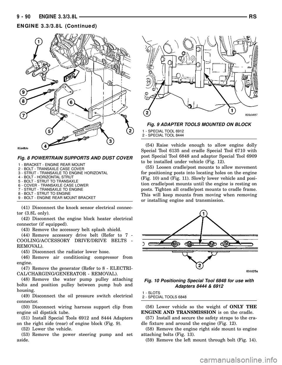
(51) Install Special Tools 6912 and 8444 Adapters
on the right side (rear) of engine block (Fig. 9).
(52) Lower the vehicle.
(53) Remove the power steering pump and set
aside.(54) Raise vehicle enough to allow engine dolly
Special Tool 6135 and cradle Special Tool 6710 with
post Special Tool 6848 and adaptor Special Tool 6909
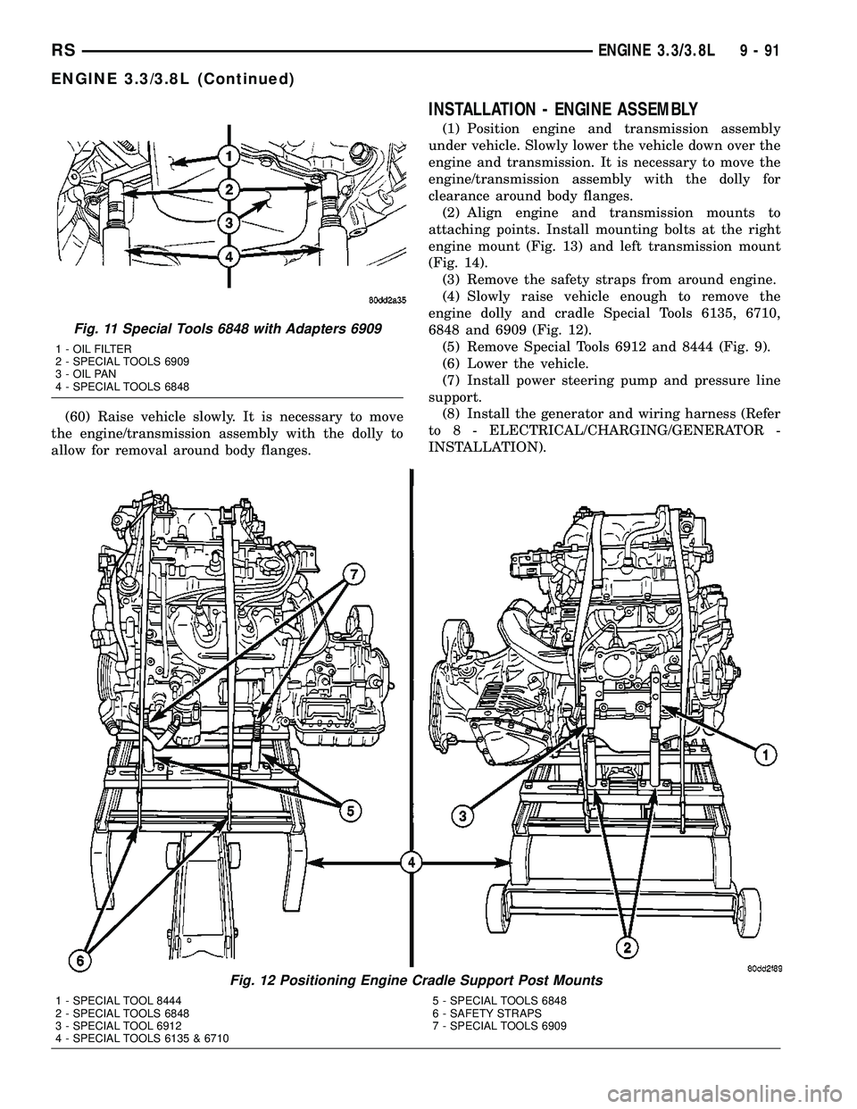
to be installed under vehicle (Fig. 12).
(55) Loosen cradle/post mounts to allow movement
for positioning posts into locating holes on the engine
(Fig. 10) and (Fig. 11). Slowly lower vehicle and posi-
tion cradle/post mounts until the engine is resting on
posts. Tighten all cradle/post mounts to cradle frame.
This will keep mounts from moving when removing
or installing engine and transmission.
(56) Lower vehicle so the weight ofONLY THE
ENGINE AND TRANSMISSIONis on the cradle.
(57) Install and secure the safety straps to the cra-
dle fixture and around the engine (Fig. 12).
(58) Remove the engine right side mount to engine
attaching bolts (Fig. 13).
(59) Remove the left mount through bolt (Fig. 14).
Fig. 8 POWERTRAIN SUPPORTS AND DUST COVER
1 - BRACKET - ENGINE REAR MOUNT
2 - BOLT - TRANSAXLE CASE COVER
3 - STRUT - TRANSAXLE TO ENGINE HORIZONTAL
4 - BOLT - HORIZONTAL STRUT
5 - BOLT - STRUT TO TRANSAXLE
6 - COVER - TRANSAXLE CASE LOWER
7 - STRUT - TRANSAXLE TO ENGINE
8 - BOLT - STRUT TO ENGINE
9 - BOLT - ENGINE REAR MOUNT BRACKET
Fig. 9 ADAPTER TOOLS MOUNTED ON BLOCK
1 - SPECIAL TOOL 6912
2 - SPECIAL TOOL 8444
Fig. 10 Positioning Special Tool 6848 for use with
Adapters 8444 & 6912
1 - SLOTS
2 - SPECIAL TOOLS 6848
9 - 90 ENGINE 3.3/3.8LRS
ENGINE 3.3/3.8L (Continued)
Page 1268 of 2339
(60) Raise vehicle slowly. It is necessary to move
the engine/transmission assembly with the dolly to
allow for removal around body flanges.
INSTALLATION - ENGINE ASSEMBLY
(1) Position engine and transmission assembly
under vehicle. Slowly lower the vehicle down over the
engine and transmission. It is necessary to move the
engine/transmission assembly with the dolly for
clearance around body flanges.
(2) Align engine and transmission mounts to
attaching points. Install mounting bolts at the right
engine mount (Fig. 13) and left transmission mount
(Fig. 14).
(3) Remove the safety straps from around engine.
(4) Slowly raise vehicle enough to remove the
engine dolly and cradle Special Tools 6135, 6710,
6848 and 6909 (Fig. 12).
(5) Remove Special Tools 6912 and 8444 (Fig. 9).
(6) Lower the vehicle.
(7) Install power steering pump and pressure line
support.
(8) Install the generator and wiring harness (Refer
to 8 - ELECTRICAL/CHARGING/GENERATOR -
INSTALLATION).
Fig. 12 Positioning Engine Cradle Support Post Mounts
1 - SPECIAL TOOL 8444
2 - SPECIAL TOOLS 6848
3 - SPECIAL TOOL 6912
4 - SPECIAL TOOLS 6135 & 67105 - SPECIAL TOOLS 6848
6 - SAFETY STRAPS
7 - SPECIAL TOOLS 6909
Fig. 11 Special Tools 6848 with Adapters 6909
1 - OIL FILTER
2 - SPECIAL TOOLS 6909
3 - OIL PAN
4 - SPECIAL TOOLS 6848
RSENGINE 3.3/3.8L9-91
ENGINE 3.3/3.8L (Continued)
Page 1387 of 2339
FUEL INJECTION
OPERATION
OPERATION - INJECTION SYSTEM
All engines used in this section have a sequential
Multi-Port Electronic Fuel Injection system. The MPI
system is computer regulated and provides precise
air/fuel ratios for all driving conditions. The Power-
train Control Module (PCM) operates the fuel injec-
tion system.
The PCM regulates:
²Ignition timing
²Air/fuel ratio
²Emission control devices
²Cooling fan
²Charging system
²Idle speed
²Vehicle speed control
Various sensors provide the inputs necessary for
the PCM to correctly operate these systems. In addi-
tion to the sensors, various switches also provide
inputs to the PCM.
The PCM can adapt its programming to meet
changing operating conditions.
Fuel is injected into the intake port above the
intake valve in precise metered amounts through
electrically operated injectors. The PCM fires the
injectors in a specific sequence. Under most operat-
ing conditions, the PCM maintains an air fuel ratio
of 14.7 parts air to 1 part fuel by constantly adjust-
ing injector pulse width. Injector pulse width is the
length of time the injector is open.
The PCM adjusts injector pulse width by opening
and closing the ground path to the injector. Engine
RPM (speed) and manifold absolute pressure (air
density) are theprimaryinputs that determine
injector pulse width.
OPERATION - MODES OF OPERATION
As input signals to the PCM change, the PCM
adjusts its response to output devices. For example,
the PCM must calculate a different injector pulse
width and ignition timing for idle than it does for
Wide Open Throttle (WOT). There are several differ-
ent modes of operation that determine how the PCM
responds to the various input signals.
There are two different areas of operation, OPEN
LOOP and CLOSED LOOP.
During OPEN LOOP modes the PCM receives
input signals and responds according to preset PCM
programming. Inputs from the upstream and down-
stream heated oxygen sensors are not monitored dur-
ing OPEN LOOP modes, except for heated oxygensensor diagnostics (they are checked for shorted con-
ditions at all times).
During CLOSED LOOP modes the PCM monitors
the inputs from the upstream and downstream
heated oxygen sensors. The upstream heated oxygen
sensor input tells the PCM if the calculated injector
pulse width resulted in the ideal air-fuel ratio of 14.7
to one. By monitoring the exhaust oxygen content
through the upstream heated oxygen sensor, the
PCM can fine tune injector pulse width. Fine tuning
injector pulse width allows the PCM to achieve opti-
mum fuel economy combined with low emissions.
For the PCM to enter CLOSED LOOP operation,
the following must occur:
(1) Engine coolant temperature must be over 35ÉF.
²If the coolant is over 35ÉF the PCM will wait 38
seconds.
²If the coolant is over 50ÉF the PCM will wait 15
seconds.
²If the coolant is over 167ÉF the PCM will wait 3
seconds.
(2) For other temperatures the PCM will interpo-
late the correct waiting time.
(3) O2 sensor must read either greater than 0.745
volts or less than 0.29 volt.
(4) The multi-port fuel injection systems has the
following modes of operation:
²Ignition switch ON (Zero RPM)
²Engine start-up
²Engine warm-up
²Cruise
²Idle
²Acceleration
²Deceleration
²Wide Open Throttle
²Ignition switch OFF
(5) The engine start-up (crank), engine warm-up,
deceleration with fuel shutoff and wide open throttle
modes are OPEN LOOP modes. Under most operat-
ing conditions, the acceleration, deceleration (with
A/C on), idle and cruise modes,with the engine at
operating temperatureare CLOSED LOOP modes.
IGNITION SWITCH ON (ZERO RPM) MODE
When the ignition switch activates the fuel injec-
tion system, the following actions occur:
²The PCM monitors the engine coolant tempera-
ture sensor and throttle position sensor input. The
PCM determines basic fuel injector pulse width from
this input.
²The PCM determines atmospheric air pressure
from the MAP sensor input to modify injector pulse
width.
When the key is in the ON position and the engine
is not running (zero rpm), the Auto Shutdown (ASD)
and fuel pump relays de-energize after approximately
14 - 22 FUEL INJECTIONRS
Page 2217 of 2339
A/C SYSTEM
WARNING: THE AIR CONDITIONING SYSTEM CON-
TAINS REFRIGERANT UNDER HIGH PRESSURE.
SEVERE PERSONAL INJURY MAY RESULT FROM
IMPROPER SERVICE PROCEDURES. REPAIRS
SHOULD ONLY BE PERFORMED BY QUALIFIED
SERVICE PERSONNEL.
AVOID BREATHING THE REFRIGERANT AND
REFRIGERANT OIL VAPOR OR MIST. EXPOSURE
MAY IRRITATE THE EYES, NOSE, AND/OR THROAT.
WEAR EYE PROTECTION WHEN SERVICING THE
AIR CONDITIONING REFRIGERANT SYSTEM. SERI-
OUS EYE INJURY CAN RESULT FROM DIRECT
CONTACT WITH THE REFRIGERANT. IF EYE CON-
TACT OCCURS, SEEK MEDICAL ATTENTION IMME-
DIATELY.
DO NOT EXPOSE THE REFRIGERANT TO OPEN
FLAME. POISONOUS GAS IS CREATED WHEN
REFRIGERANT IS BURNED. AN ELECTRONIC LEAK
DETECTOR IS RECOMMENDED.
IF ACCIDENTAL SYSTEM DISCHARGE OCCURS,
VENTILATE THE WORK AREA BEFORE RESUMING
SERVICE. LARGE AMOUNTS OF REFRIGERANT
RELEASED IN A CLOSED WORK AREA WILL DIS-
PLACE THE OXYGEN AND CAUSE SUFFOCATION.
THE EVAPORATION RATE OF R-134a REFRIGER-
ANT AT AVERAGE TEMPERATURE AND ALTITUDE
IS EXTREMELY HIGH. AS A RESULT, ANYTHING
THAT COMES IN CONTACT WITH THE REFRIGER-
ANT WILL FREEZE. ALWAYS PROTECT THE SKIN
OR DELICATE OBJECTS FROM DIRECT CONTACT
WITH THE REFRIGERANT.
THE R-134a SERVICE EQUIPMENT OR THE VEHI-
CLE REFRIGERANT SYSTEM SHOULD NOT BE
PRESSURE TESTED OR LEAK TESTED WITH COM-
PRESSED AIR. SOME MIXTURES OF AIR AND
R-134a HAVE BEEN SHOWN TO BE COMBUSTIBLE
AT ELEVATED PRESSURES. THESE MIXTURES ARE
POTENTIALLY DANGEROUS, AND MAY RESULT IN
FIRE OR EXPLOSION CAUSING INJURY OR PROP-
ERTY DAMAGE.
CAUTION - A/C SYSTEM
CAUTION: Liquid refrigerant is corrosive to metal
surfaces. Follow the operating instructions supplied
with the service equipment being used.
Never add R-12 to a refrigerant system designed to
use R-134a and do not use R-12 equipment or parts
on the R-134a system. Damage to the system will
result.
R-12 refrigerant oil must not be mixed with R-134a
refrigerant oil. They are not compatible and damage
to the system will result.Do not overcharge the refrigerant system. Over-
charging will cause excessive compressor head
pressure and can cause noise and system failure.
Recover the refrigerant before opening any fitting
or connection. Open the fittings with caution, even
after the system has been discharged. Never open
or loosen a connection before recovering the refrig-
erant.
If equipped, do not remove the secondary retention
clip from any spring-lock coupler connection while
the refrigerant system is under pressure. Recover
the refrigerant before removing the secondary
retention clip. Open the fittings with caution, even
after the system has been discharged. Never open
or loosen a connection before recovering the refrig-
erant.
Do not open the refrigerant system or uncap a
replacement component until you are ready to ser-
vice the system. This will prevent contamination in
the system. Before disconnecting a component,
clean the outside of the fittings thoroughly to pre-
vent contamination from entering the refrigerant
system. Immediately after disconnecting a compo-
nent from the refrigerant system, seal the open fit-
tings with a cap or plug.
Refrigerant oil will absorb moisture from the atmo-
sphere if left uncapped. Do not open a container of
refrigerant oil until you are ready to use it. Replace
the cap on the oil container immediately after using.
Store refrigerant oil only in a clean, airtight, and
moisture-free container.
Keep service tools and the work area clean. Con-
tamination of the refrigerant system must be
avoided.
CAUTION: The use of A/C system sealers may
result in damage to A/C refrigerant recovery/evacu-
ation/recharging equipment and/or A/C systems.
Many federal, state/provincial and local regulations
prohibit the recharge of A/C systems with known
leaks. DaimlerChrysler recommends the detection
of A/C system leaks through the use of approved
leak detectors and fluorescent leak detection dyes.
Vehicles found with A/C system sealers should be
treated as contaminated and replacement of the
entire A/C refrigerant system is recommended. A/C
systems found to be contaminated with A/C system
sealers, A/C stop-leak products or seal conditioners
voids the warranty for the A/C system.
24 - 66 PLUMBING - FRONTRS
PLUMBING - FRONT (Continued)
Page 2219 of 2339
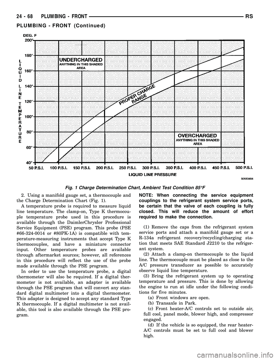
2. Using a manifold gauge set, a thermocouple and
the Charge Determination Chart (Fig. 1).
A temperature probe is required to measure liquid
line temperature. The clamp-on, Type K thermocou-
ple temperature probe used in this procedure is
available through the DaimlerChrysler Professional
Service Equipment (PSE) program. This probe (PSE
#66-324-0014 or #80PK-1A) is compatible with tem-
perature-measuring instruments that accept Type K
thermocouples, and have a miniature connector
input. Other temperature probes are available
through aftermarket sources; however, all references
in this procedure will reflect the use of the probe
made available through the PSE program.
In order to use the temperature probe, a digital
thermometer will also be required. If a digital ther-
mometer is not available, an adapter is available
through the PSE program that will convert any stan-
dard digital multimeter into a digital thermometer.
This adapter is designed to accept any standard Type
K thermocouple. If a digital multimeter is not avail-
able, this tool is also available through the PSE pro-
gram.NOTE: When connecting the service equipment
couplings to the refrigerant system service ports,
be certain that the valve of each coupling is fully
closed. This will reduce the amount of effort
required to make the connection.
(1) Remove the caps from the refrigerant system
service ports and attach a manifold gauge set or a
R-134a refrigerant recovery/recycling/charging sta-
tion that meets SAE Standard J2210 to the refriger-
ant system.
(2) Attach a clamp-on thermocouple to the liquid
line. The thermocouple must be placed as close to the
A/C pressure transducer as possible to accurately
observe liquid line temperature.
(3) Bring the refrigerant system up to operating
temperature and pressure. This is done by allowing
the engine to run at idle under the following condi-
tions for five minutes.
(a) Front windows are open.
(b) Transaxle in Park.
(c) Front heater-A/C controls set to outside air,
full cool, panel mode, blower high, and compressor
engaged.
(d) If the vehicle is so equipped, the rear heater-
A/C controls must be set to full cool and blower
high.
Fig. 1 Charge Determination Chart, Ambient Test Condition 85ÉF
24 - 68 PLUMBING - FRONTRS
PLUMBING - FRONT (Continued)
Page 2220 of 2339
(4) Raise the liquid line (discharge) pressure to
about 1793 kPa (260 psi) by placing a piece of card-
board over part of the front side of the condenser. To
place the cardboard properly, remove the upper radi-
ator sight shield from the front fascia. Cover only
enough of the condenser to raise and maintain the
liquid line pressure at the specified level.
(5) Observe the liquid line (discharge) pressure
and liquid line temperature. Using the Charge Deter-
mination Chart (Fig. 1), determine whether the
refrigerant system is operating within the Proper
Charge Range.
(a) If the refrigerant system is operating in the
Undercharged area of the chart, add 0.057 kilo-
gram (0.125 pound or 2 ounces) of refrigerant to
the system.
(b) If the refrigerant system is operating in the
Overcharged area of the chart, reclaim 0.057 kilo-
gram (0.125 pound or 2 ounces) of refrigerant from
the system.
(6) Recheck the system charge level following each
refrigerant adjustment. Continue this process until
the system readings are in the Proper Charge Range
area on the Charge Determination Chart.
STANDARD PROCEDURE
HANDLING TUBING AND FITTINGS
CAUTION: The system must be completely empty
before opening any fitting or connection in the
refrigeration system. Open fittings with caution
even after the system has been emptied. If any
pressure is noticed as a fitting is loosened,
retighten fitting and evacuate the system again.
A good rule for the flexible hose lines is to keep the
radius of all bends at least 10 times the diameter of
the hose. Sharper bends will reduce the flow of
refrigerant. The flexible hose lines should be routed
so they are at least 3 inches (80 mm) from the
exhaust manifold. Inspect all flexible hose lines to
make sure they are in good condition and properly
routed.
The use of correct wrenches when making connec-
tions is very important. Improper wrenches or
improper use of wrenches can damage the fittings.
The internal parts of the A/C system will remain sta-
ble as long as moisture-free refrigerant and refrig-
erant oil is used. Abnormal amounts of dirt,
moisture or air can upset the chemical stability.
This may cause operational troubles or even seri-
ous damage if present in more than very small
quantities. Before disconnecting a component,
clean the outside of the fittings thoroughly to pre-
vent contamination from entering the refrigerant
system.When opening a refrigeration system, have every-
thing you will need to repair the system ready. This
will minimize the amount of time the system must
be opened. Cap or plug all lines and fittings as
soon as they are opened. This will help prevent the
entrance of dirt and moisture. All new lines and
components should be capped or sealed until they
are ready to be used. Before connecting a compo-
nent, clean the outside of the fittings thoroughly to
prevent contamination from entering the refrigerant
system.
All tools, including the refrigerant dispensing mani-
fold, the manifold gauge set, and test hoses should
be kept clean and dry.
Kinks in the refrigerant tubing or sharp bends in
the refrigerant hose lines will greatly reduce the
capacity of the entire system. High pressures are pro-
duced in the system when it is operating. Extreme
care must be exercised to make sure that all connec-
tions are pressure tight. Dirt and moisture can enter
the system when it is opened for repair or replace-
ment of lines or components. The refrigerant oil will
absorb moisture readily out of the air. This moisture
will convert into acids within a closed system.
REFRIGERANT SYSTEM SERVICE EQUIPMENT
WARNING: EYE PROTECTION MUST BE WORN
WHEN SERVICING AN AIR CONDITIONING REFRIG-
ERANT SYSTEM. TURN OFF (ROTATE CLOCKWISE)
ALL VALVES ON THE EQUIPMENT BEING USED
BEFORE CONNECTING TO, OR DISCONNECTING
FROM THE REFRIGERANT SYSTEM. FAILURE TO
OBSERVE THESE WARNINGS MAY RESULT IN PER-
SONAL INJURY.
WARNING: REVIEW THE WARNINGS AND CAU-
TIONS IN THE FRONT OF THIS SECTION BEFORE
PERFORMING THE FOLLOWING OPERATION (Refer
to 24 - HEATING & AIR CONDITIONING/PLUMBING -
WARNING) and (Refer to 24 - HEATING & AIR CON-
DITIONING/PLUMBING - CAUTION).
RECOVERY/RECYCLING STATION
When servicing the air conditioning system, a
R-134a refrigerant recovery/recycling/charging sta-
tion that meets SEA Standard J2210 must be used
(Fig. 2). Contact an automotive service equipment
supplier for refrigerant recovery/recycling/charging
equipment. See the operating instructions supplied
by the equipment manufacturer for proper care and
use of this equipment.
RSPLUMBING - FRONT24-69
PLUMBING - FRONT (Continued)