2005 CHRYSLER CARAVAN battery
[x] Cancel search: batteryPage 1298 of 2339
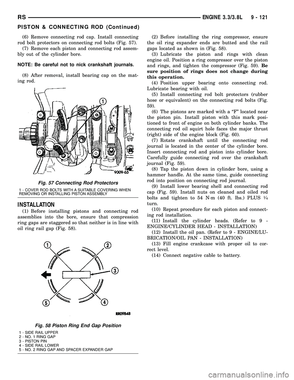
(6) Remove connecting rod cap. Install connecting
rod bolt protectors on connecting rod bolts (Fig. 57).
(7) Remove each piston and connecting rod assem-
bly out of the cylinder bore.
NOTE: Be careful not to nick crankshaft journals.
(8) After removal, install bearing cap on the mat-
ing rod.
INSTALLATION
(1) Before installing pistons and connecting rod
assemblies into the bore, ensure that compression
ring gaps are staggered so that neither is in line with
oil ring rail gap (Fig. 58).(2) Before installing the ring compressor, ensure
the oil ring expander ends are butted and the rail
gaps located as shown in (Fig. 58).
(3) Lubricate the piston and rings with clean
engine oil. Position a ring compressor over the piston
and rings, and tighten the compressor (Fig. 59).Be
sure position of rings does not change during
this operation.
(4) Position upper bearing onto connecting rod.
Lubricate bearing with oil.
(5) Install connecting rod bolt protectors (rubber
hose or equivalent) on the connecting rod bolts (Fig.
59).
(6) The pistons are marked with a ªFº located near
the piston pin. Install piston with this mark posi-
tioned to front of engine on both cylinder banks. The
connecting rod oil squirt hole faces the major thrust
(right) side of the engine block (Fig. 60).
(7) Rotate crankshaft until the connecting rod
journal is located in the center of the cylinder bore.
Insert connecting rod and piston into cylinder bore.
Carefully guide connecting rod over the crankshaft
journal (Fig. 59).
(8) Tap the piston down in cylinder bore, using a
hammer handle. At the same time, guide connecting
rod into position on connecting rod journal.
(9) Install lower bearing shell and connecting rod
cap (Fig. 59). Install nuts on cleaned and oiled rod
bolts and tighten to 54 N´m (40 ft. lbs.) PLUS
1¤4
turn.
(10) Repeat procedure for each piston and connect-
ing rod installation.
(11) Install the cylinder heads. (Refer to 9 -
ENGINE/CYLINDER HEAD - INSTALLATION)
(12) Install the oil pan. (Refer to 9 - ENGINE/LU-
BRICATION/OIL PAN - INSTALLATION)
(13) Fill engine crankcase with proper oil to cor-
rect level.
(14) Connect negative cable to battery.
Fig. 57 Connecting Rod Protectors
1 - COVER ROD BOLTS WITH A SUITABLE COVERING WHEN
REMOVING OR INSTALLING PISTON ASSEMBLY
Fig. 58 Piston Ring End Gap Position
1 - SIDE RAIL UPPER
2 - NO. 1 RING GAP
3 - PISTON PIN
4 - SIDE RAIL LOWER
5 - NO. 2 RING GAP AND SPACER EXPANDER GAP
RSENGINE 3.3/3.8L9 - 121
PISTON & CONNECTING ROD (Continued)
Page 1307 of 2339
(11) Install the timing chain cover (Refer to 9 -
ENGINE/VALVE TIMING/TIMING CHAIN COVER -
INSTALLATION).
(12) Install the oil pick-up tube and oil pan (Refer
to 9 - ENGINE/LUBRICATION/OIL PAN - INSTAL-
LATION).
(13) Install the transaxle to the engine.
(14) Install the engine assembly (Refer to 9 -
ENGINE - INSTALLATION).
CRANKSHAFT OIL SEAL -
FRONT
REMOVAL
(1) Disconnect negative cable from battery.(2) Raise vehicle on hoist. Remove right wheel and
inner splash shield.
(3) Remove accessory drive belt. (Refer to 7 -
COOLING/ACCESSORY DRIVE/DRIVE BELTS -
REMOVAL)
(4) Remove crankshaft damper. (Refer to 9 -
ENGINE/ENGINE BLOCK/VIBRATION DAMPER -
REMOVAL)
(5) Position Special Tool 6341A on crankshaft nose.
Carefully screw the tool into the seal until it engages
firmly (Fig. 78). Be careful not to damage that crank-
shaft seal surface of cover
(6) Remove oil seal by turning the forcing screw
until the seal disengages from the cover (Fig. 79).
INSTALLATION
(1) Position Special Tool C-4992-2 Guide, on the
crankshaft nose (Fig. 80).
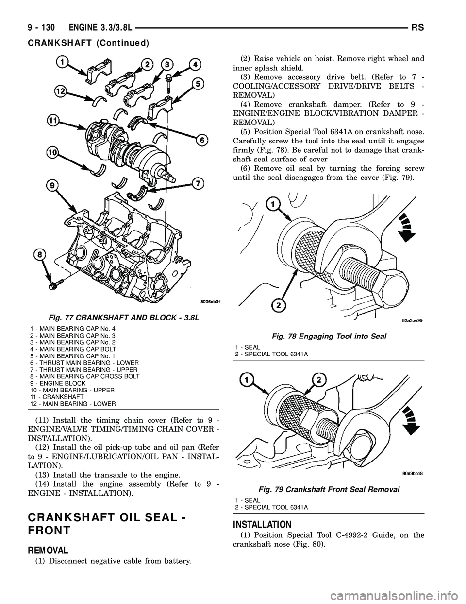
Fig. 77 CRANKSHAFT AND BLOCK - 3.8L
1 - MAIN BEARING CAP No. 4
2 - MAIN BEARING CAP No. 3
3 - MAIN BEARING CAP No. 2
4 - MAIN BEARING CAP BOLT
5 - MAIN BEARING CAP No. 1
6 - THRUST MAIN BEARING - LOWER
7 - THRUST MAIN BEARING - UPPER
8 - MAIN BEARING CAP CROSS BOLT
9 - ENGINE BLOCK
10 - MAIN BEARING - UPPER
11 - CRANKSHAFT
12 - MAIN BEARING - LOWER
Fig. 78 Engaging Tool into Seal
1 - SEAL
2 - SPECIAL TOOL 6341A
Fig. 79 Crankshaft Front Seal Removal
1 - SEAL
2 - SPECIAL TOOL 6341A
9 - 130 ENGINE 3.3/3.8LRS
CRANKSHAFT (Continued)
Page 1308 of 2339
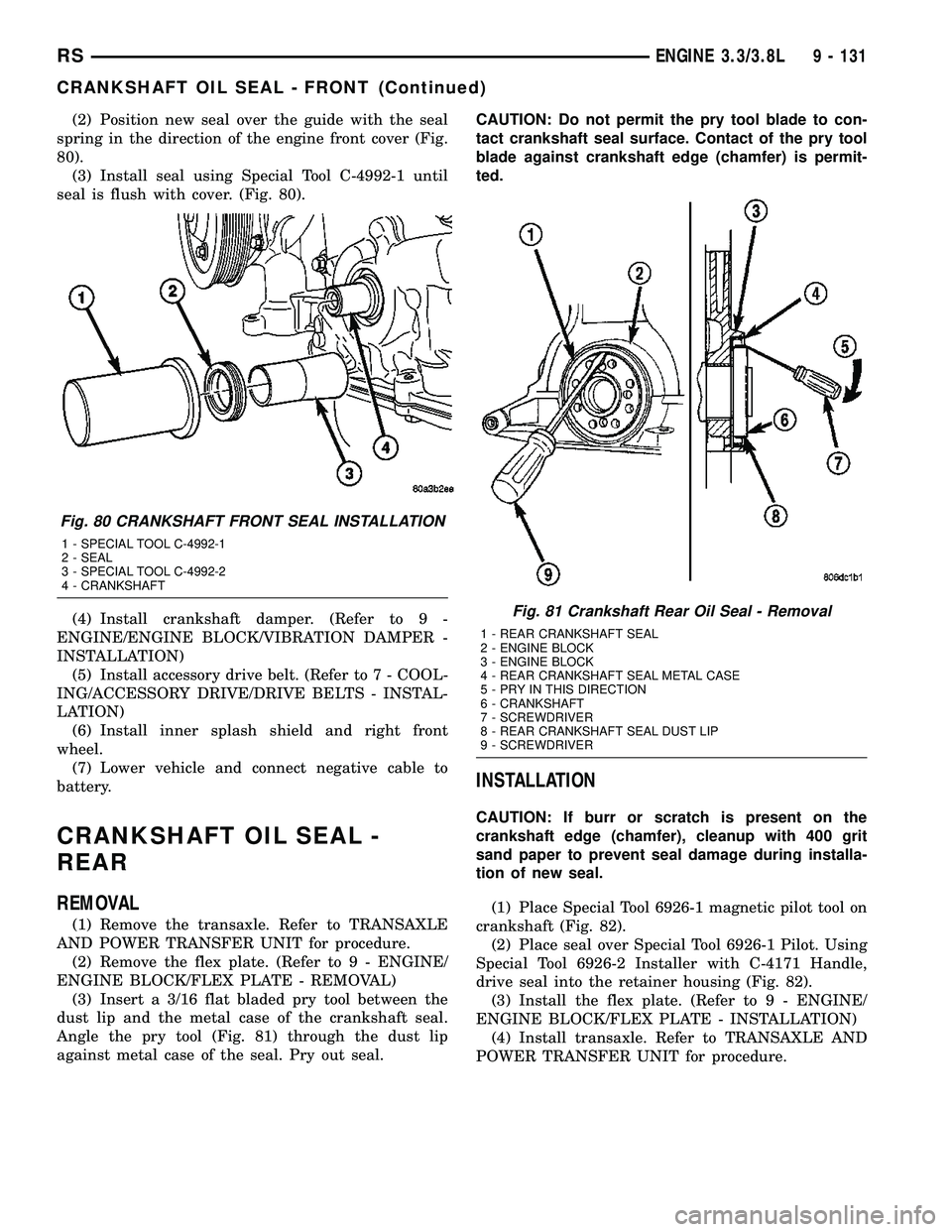
(2) Position new seal over the guide with the seal
spring in the direction of the engine front cover (Fig.
80).
(3) Install seal using Special Tool C-4992-1 until
seal is flush with cover. (Fig. 80).
(4) Install crankshaft damper. (Refer to 9 -
ENGINE/ENGINE BLOCK/VIBRATION DAMPER -
INSTALLATION)
(5) Install accessory drive belt. (Refer to 7 - COOL-
ING/ACCESSORY DRIVE/DRIVE BELTS - INSTAL-
LATION)
(6) Install inner splash shield and right front
wheel.
(7) Lower vehicle and connect negative cable to
battery.
CRANKSHAFT OIL SEAL -
REAR
REMOVAL
(1) Remove the transaxle. Refer to TRANSAXLE
AND POWER TRANSFER UNIT for procedure.
(2) Remove the flex plate. (Refer to 9 - ENGINE/
ENGINE BLOCK/FLEX PLATE - REMOVAL)
(3) Insert a 3/16 flat bladed pry tool between the
dust lip and the metal case of the crankshaft seal.
Angle the pry tool (Fig. 81) through the dust lip
against metal case of the seal. Pry out seal.CAUTION: Do not permit the pry tool blade to con-
tact crankshaft seal surface. Contact of the pry tool
blade against crankshaft edge (chamfer) is permit-
ted.
INSTALLATION
CAUTION: If burr or scratch is present on the
crankshaft edge (chamfer), cleanup with 400 grit
sand paper to prevent seal damage during installa-
tion of new seal.
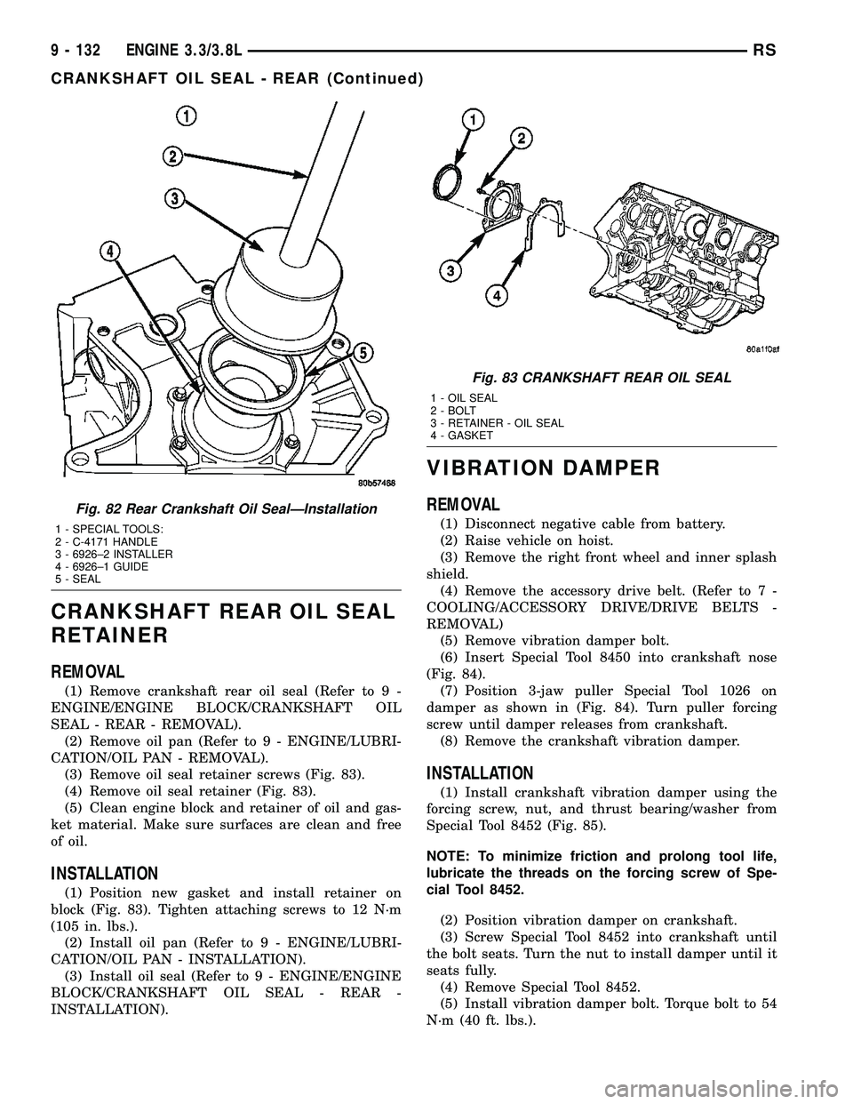
(1) Place Special Tool 6926-1 magnetic pilot tool on
crankshaft (Fig. 82).
(2) Place seal over Special Tool 6926-1 Pilot. Using
Special Tool 6926-2 Installer with C-4171 Handle,
drive seal into the retainer housing (Fig. 82).
(3) Install the flex plate. (Refer to 9 - ENGINE/
ENGINE BLOCK/FLEX PLATE - INSTALLATION)
(4) Install transaxle. Refer to TRANSAXLE AND
POWER TRANSFER UNIT for procedure.
Fig. 80 CRANKSHAFT FRONT SEAL INSTALLATION
1 - SPECIAL TOOL C-4992-1
2 - SEAL
3 - SPECIAL TOOL C-4992-2
4 - CRANKSHAFT
Fig. 81 Crankshaft Rear Oil Seal - Removal
1 - REAR CRANKSHAFT SEAL
2 - ENGINE BLOCK
3 - ENGINE BLOCK
4 - REAR CRANKSHAFT SEAL METAL CASE
5 - PRY IN THIS DIRECTION
6 - CRANKSHAFT
7 - SCREWDRIVER
8 - REAR CRANKSHAFT SEAL DUST LIP
9 - SCREWDRIVER
RSENGINE 3.3/3.8L9 - 131
CRANKSHAFT OIL SEAL - FRONT (Continued)
Page 1309 of 2339
CRANKSHAFT REAR OIL SEAL
RETAINER
REMOVAL
(1) Remove crankshaft rear oil seal (Refer to 9 -
ENGINE/ENGINE BLOCK/CRANKSHAFT OIL
SEAL - REAR - REMOVAL).
(2) Remove oil pan (Refer to 9 - ENGINE/LUBRI-
CATION/OIL PAN - REMOVAL).
(3) Remove oil seal retainer screws (Fig. 83).
(4) Remove oil seal retainer (Fig. 83).
(5) Clean engine block and retainer of oil and gas-
ket material. Make sure surfaces are clean and free
of oil.
INSTALLATION
(1) Position new gasket and install retainer on
block (Fig. 83). Tighten attaching screws to 12 N´m
(105 in. lbs.).
(2) Install oil pan (Refer to 9 - ENGINE/LUBRI-
CATION/OIL PAN - INSTALLATION).
(3) Install oil seal (Refer to 9 - ENGINE/ENGINE
BLOCK/CRANKSHAFT OIL SEAL - REAR -
INSTALLATION).
VIBRATION DAMPER
REMOVAL
(1) Disconnect negative cable from battery.
(2) Raise vehicle on hoist.
(3) Remove the right front wheel and inner splash
shield.
(4) Remove the accessory drive belt. (Refer to 7 -
COOLING/ACCESSORY DRIVE/DRIVE BELTS -
REMOVAL)
(5) Remove vibration damper bolt.
(6) Insert Special Tool 8450 into crankshaft nose
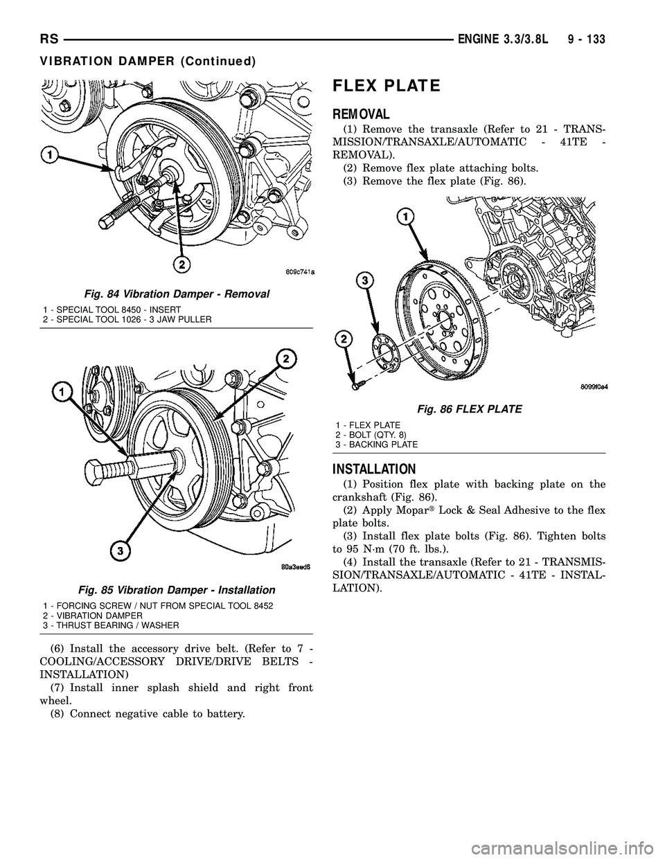
(Fig. 84).
(7) Position 3-jaw puller Special Tool 1026 on
damper as shown in (Fig. 84). Turn puller forcing
screw until damper releases from crankshaft.
(8) Remove the crankshaft vibration damper.
INSTALLATION
(1) Install crankshaft vibration damper using the
forcing screw, nut, and thrust bearing/washer from
Special Tool 8452 (Fig. 85).
NOTE: To minimize friction and prolong tool life,
lubricate the threads on the forcing screw of Spe-
cial Tool 8452.
(2) Position vibration damper on crankshaft.
(3) Screw Special Tool 8452 into crankshaft until
the bolt seats. Turn the nut to install damper until it
seats fully.
(4) Remove Special Tool 8452.
(5) Install vibration damper bolt. Torque bolt to 54
N´m (40 ft. lbs.).
Fig. 82 Rear Crankshaft Oil SealÐInstallation
1 - SPECIAL TOOLS:
2 - C-4171 HANDLE
3 - 6926±2 INSTALLER
4 - 6926±1 GUIDE
5 - SEAL
Fig. 83 CRANKSHAFT REAR OIL SEAL
1 - OIL SEAL
2 - BOLT
3 - RETAINER - OIL SEAL
4 - GASKET
9 - 132 ENGINE 3.3/3.8LRS
CRANKSHAFT OIL SEAL - REAR (Continued)
Page 1310 of 2339
(6) Install the accessory drive belt. (Refer to 7 -
COOLING/ACCESSORY DRIVE/DRIVE BELTS -
INSTALLATION)
(7) Install inner splash shield and right front
wheel.
(8) Connect negative cable to battery.
FLEX PLATE
REMOVAL
(1) Remove the transaxle (Refer to 21 - TRANS-
MISSION/TRANSAXLE/AUTOMATIC - 41TE -
REMOVAL).
(2) Remove flex plate attaching bolts.
(3) Remove the flex plate (Fig. 86).
INSTALLATION
(1) Position flex plate with backing plate on the
crankshaft (Fig. 86).
(2) Apply MopartLock & Seal Adhesive to the flex
plate bolts.
(3) Install flex plate bolts (Fig. 86). Tighten bolts
to 95 N´m (70 ft. lbs.).
(4) Install the transaxle (Refer to 21 - TRANSMIS-
SION/TRANSAXLE/AUTOMATIC - 41TE - INSTAL-
LATION).
Fig. 84 Vibration Damper - Removal
1 - SPECIAL TOOL 8450 - INSERT
2 - SPECIAL TOOL 1026-3JAWPULLER
Fig. 85 Vibration Damper - Installation
1 - FORCING SCREW / NUT FROM SPECIAL TOOL 8452
2 - VIBRATION DAMPER
3 - THRUST BEARING / WASHER
Fig. 86 FLEX PLATE
1 - FLEX PLATE
2 - BOLT (QTY. 8)
3 - BACKING PLATE
RSENGINE 3.3/3.8L9 - 133
VIBRATION DAMPER (Continued)
Page 1319 of 2339
OIL FILTER ADAPTER
REMOVAL
(1) Raise vehicle on hoist.
(2) Remove the oil filter.
(3) Disconnect oil pressure switch electrical con-
nector.
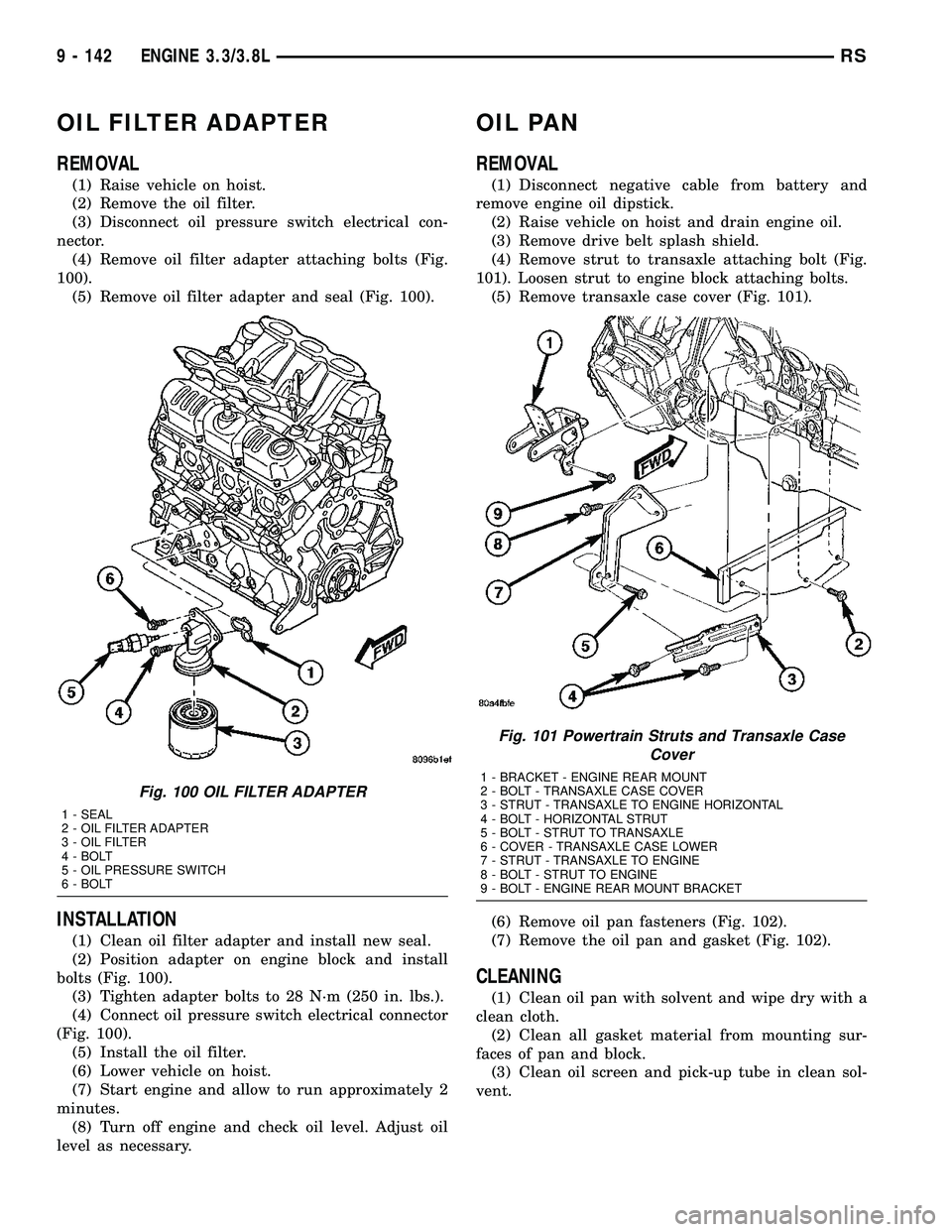
(4) Remove oil filter adapter attaching bolts (Fig.
100).
(5) Remove oil filter adapter and seal (Fig. 100).
INSTALLATION
(1) Clean oil filter adapter and install new seal.
(2) Position adapter on engine block and install
bolts (Fig. 100).
(3) Tighten adapter bolts to 28 N´m (250 in. lbs.).
(4) Connect oil pressure switch electrical connector
(Fig. 100).
(5) Install the oil filter.
(6) Lower vehicle on hoist.
(7) Start engine and allow to run approximately 2
minutes.
(8) Turn off engine and check oil level. Adjust oil
level as necessary.
OIL PAN
REMOVAL
(1) Disconnect negative cable from battery and
remove engine oil dipstick.
(2) Raise vehicle on hoist and drain engine oil.
(3) Remove drive belt splash shield.
(4) Remove strut to transaxle attaching bolt (Fig.
101). Loosen strut to engine block attaching bolts.
(5) Remove transaxle case cover (Fig. 101).
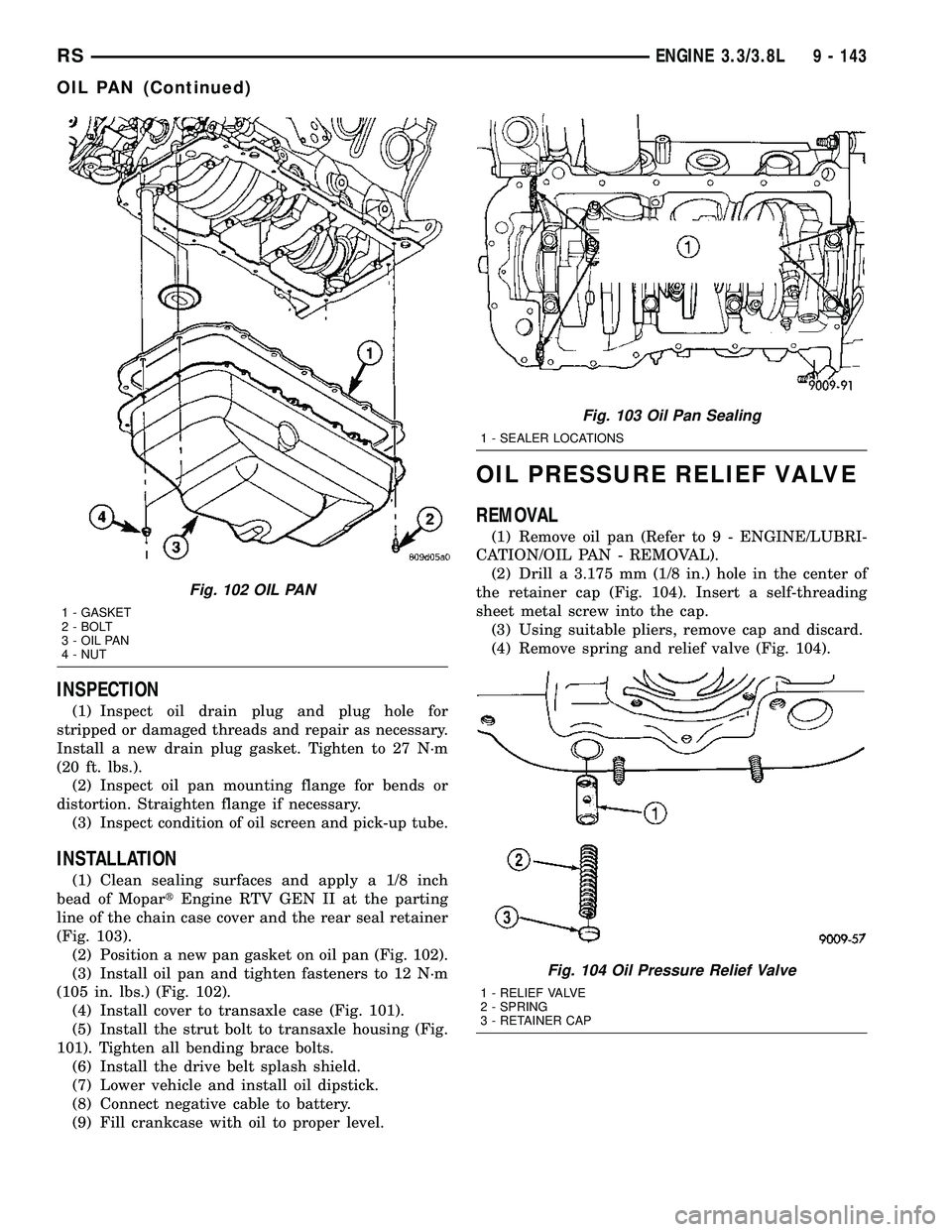
(6) Remove oil pan fasteners (Fig. 102).
(7) Remove the oil pan and gasket (Fig. 102).
CLEANING
(1) Clean oil pan with solvent and wipe dry with a
clean cloth.
(2) Clean all gasket material from mounting sur-
faces of pan and block.
(3) Clean oil screen and pick-up tube in clean sol-
vent.
Fig. 100 OIL FILTER ADAPTER
1 - SEAL
2 - OIL FILTER ADAPTER
3 - OIL FILTER
4 - BOLT
5 - OIL PRESSURE SWITCH
6 - BOLT
Fig. 101 Powertrain Struts and Transaxle Case
Cover
1 - BRACKET - ENGINE REAR MOUNT
2 - BOLT - TRANSAXLE CASE COVER
3 - STRUT - TRANSAXLE TO ENGINE HORIZONTAL
4 - BOLT - HORIZONTAL STRUT
5 - BOLT - STRUT TO TRANSAXLE
6 - COVER - TRANSAXLE CASE LOWER
7 - STRUT - TRANSAXLE TO ENGINE
8 - BOLT - STRUT TO ENGINE
9 - BOLT - ENGINE REAR MOUNT BRACKET
9 - 142 ENGINE 3.3/3.8LRS
Page 1320 of 2339
INSPECTION
(1) Inspect oil drain plug and plug hole for
stripped or damaged threads and repair as necessary.
Install a new drain plug gasket. Tighten to 27 N´m
(20 ft. lbs.).
(2) Inspect oil pan mounting flange for bends or
distortion. Straighten flange if necessary.
(3) Inspect condition of oil screen and pick-up tube.
INSTALLATION
(1) Clean sealing surfaces and apply a 1/8 inch
bead of MopartEngine RTV GEN II at the parting
line of the chain case cover and the rear seal retainer
(Fig. 103).
(2) Position a new pan gasket on oil pan (Fig. 102).
(3) Install oil pan and tighten fasteners to 12 N´m
(105 in. lbs.) (Fig. 102).
(4) Install cover to transaxle case (Fig. 101).
(5) Install the strut bolt to transaxle housing (Fig.
101). Tighten all bending brace bolts.
(6) Install the drive belt splash shield.
(7) Lower vehicle and install oil dipstick.
(8) Connect negative cable to battery.
(9) Fill crankcase with oil to proper level.
OIL PRESSURE RELIEF VALVE
REMOVAL
(1) Remove oil pan (Refer to 9 - ENGINE/LUBRI-
CATION/OIL PAN - REMOVAL).
(2) Drill a 3.175 mm (1/8 in.) hole in the center of
the retainer cap (Fig. 104). Insert a self-threading
sheet metal screw into the cap.
(3) Using suitable pliers, remove cap and discard.
(4) Remove spring and relief valve (Fig. 104).
Fig. 102 OIL PAN
1 - GASKET
2 - BOLT
3 - OIL PAN
4 - NUT
Fig. 103 Oil Pan Sealing
1 - SEALER LOCATIONS
Fig. 104 Oil Pressure Relief Valve
1 - RELIEF VALVE
2 - SPRING
3 - RETAINER CAP
RSENGINE 3.3/3.8L9 - 143
OIL PAN (Continued)
Page 1325 of 2339
STANDARD PROCEDURE - INTAKE MANIFOLD
VACUUM PORT REPAIR
The composite intake manifold vacuum ports can
be repaired. Although, if the manifold plenum cham-
ber is damaged or cracked, the manifold must be
replaced.
To repair a broken or damaged vacuum nipple
(port) on the composite intake manifold, perform the
following procedure:
PARTS REQUIRED TOOLS REQUIRED
´ Brass Nipple ± 1/49
O.D. x 1/89pipe thread
(LDP/Speed Control Port)´ Pipe Tap ± 1/89-18
NPT
´ Drill Bit ± 11/329
´ File/Sandpaper
´ Brass Nipple ± 1/29
O.D. x 1/49pipe thread
(Brake Booster Port)´ Pipe Tap ± 1/49-18
NPT
´ Drill Bit ± 7/169
´ File/Sandpaper
NOTE: While performing this procedure, avoid get-
ting the manifold material residue into the plenum
chamber.
(1) File or sand the remaining port back until a
flat surface is obtained (plane normal to nipple (port)
axis).
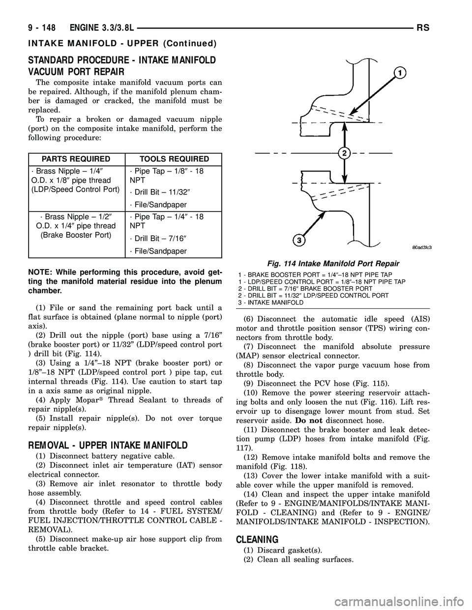
(2) Drill out the nipple (port) base using a 7/16º
(brake booster port) or 11/32º (LDP/speed control port
) drill bit (Fig. 114).
(3) Using a 1/4º±18 NPT (brake booster port) or
1/8º±18 NPT (LDP/speed control port ) pipe tap, cut
internal threads (Fig. 114). Use caution to start tap
in a axis same as original nipple.
(4) Apply MopartThread Sealant to threads of
repair nipple(s).
(5) Install repair nipple(s). Do not over torque
repair nipple(s).
REMOVAL - UPPER INTAKE MANIFOLD
(1) Disconnect battery negative cable.
(2) Disconnect inlet air temperature (IAT) sensor
electrical connector.
(3) Remove air inlet resonator to throttle body
hose assembly.
(4) Disconnect throttle and speed control cables
from throttle body (Refer to 14 - FUEL SYSTEM/
FUEL INJECTION/THROTTLE CONTROL CABLE -
REMOVAL).
(5) Disconnect make-up air hose support clip from
throttle cable bracket.(6) Disconnect the automatic idle speed (AIS)
motor and throttle position sensor (TPS) wiring con-
nectors from throttle body.
(7) Disconnect the manifold absolute pressure
(MAP) sensor electrical connector.
(8) Disconnect the vapor purge vacuum hose from
throttle body.
(9) Disconnect the PCV hose (Fig. 115).
(10) Remove the power steering reservoir attach-
ing bolts and only loosen the nut (Fig. 116). Lift res-
ervoir up to disengage lower mount from stud. Set
reservoir aside.Do notdisconnect hose.
(11) Disconnect the brake booster and leak detec-
tion pump (LDP) hoses from intake manifold (Fig.
117).
(12) Remove intake manifold bolts and remove the
manifold (Fig. 118).
(13) Cover the lower intake manifold with a suit-
able cover while the upper manifold is removed.
(14) Clean and inspect the upper intake manifold
(Refer to 9 - ENGINE/MANIFOLDS/INTAKE MANI-
FOLD - CLEANING) and (Refer to 9 - ENGINE/
MANIFOLDS/INTAKE MANIFOLD - INSPECTION).
CLEANING
(1) Discard gasket(s).
(2) Clean all sealing surfaces.
Fig. 114 Intake Manifold Port Repair
1 - BRAKE BOOSTER PORT = 1/49±18 NPT PIPE TAP
1 - LDP/SPEED CONTROL PORT = 1/89±18 NPT PIPE TAP
2 - DRILL BIT = 7/169BRAKE BOOSTER PORT
2 - DRILL BIT = 11/329LDP/SPEED CONTROL PORT
3 - INTAKE MANIFOLD
9 - 148 ENGINE 3.3/3.8LRS
INTAKE MANIFOLD - UPPER (Continued)