2005 CHRYSLER CARAVAN fuel filter
[x] Cancel search: fuel filterPage 1258 of 2339
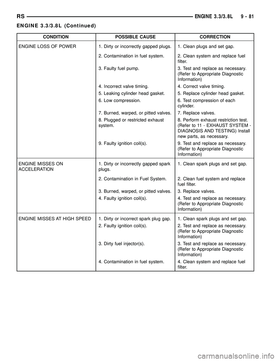
CONDITION POSSIBLE CAUSE CORRECTION
ENGINE LOSS OF POWER 1. Dirty or incorrectly gapped plugs. 1. Clean plugs and set gap.
2. Contamination in fuel system. 2. Clean system and replace fuel
filter.
3. Faulty fuel pump. 3. Test and replace as necessary.
(Refer to Appropriate Diagnostic
Information)
4. Incorrect valve timing. 4. Correct valve timing.
5. Leaking cylinder head gasket. 5. Replace cylinder head gasket.
6. Low compression. 6. Test compression of each
cylinder.
7. Burned, warped, or pitted valves. 7. Replace valves.
8. Plugged or restricted exhaust
system.8. Perform exhaust restriction test.
(Refer to 11 - EXHAUST SYSTEM -
DIAGNOSIS AND TESTING) Install
new parts, as necessary.
9. Faulty ignition coil(s). 9. Test and replace as necessary.
(Refer to Appropriate Diagnostic
Information)
ENGINE MISSES ON
ACCELERATION1. Dirty or incorrectly gapped spark
plugs.1. Clean spark plugs and set gap.
2. Contamination in Fuel System. 2. Clean fuel system and replace
fuel filter.
3. Burned, warped, or pitted valves. 3. Replace valves.
4. Faulty ignition coil(s). 4. Test and replace as necessary.
(Refer to Appropriate Diagnostic
Information)
ENGINE MISSES AT HIGH SPEED 1. Dirty or incorrect spark plug gap. 1. Clean spark plugs and set gap.
2. Faulty ignition coil(s). 2. Test and replace as necessary.
(Refer to Appropriate Diagnostic
Information)
3. Dirty fuel injector(s). 3. Test and replace as necessary.
(Refer to Appropriate Diagnostic
Information)
4. Contamination in fuel system. 4. Clean system and replace fuel
filter.
RSENGINE 3.3/3.8L9-81
ENGINE 3.3/3.8L (Continued)
Page 1265 of 2339
(3) Place a shop towel around the spark plugs
when removing them from the engine. This will catch
any fluid that may possibly be in the cylinder under
pressure.
(4) With all spark plugs removed, rotate engine
crankshaft using a breaker bar and socket.
(5) Identify the fluid in the cylinder(s) (i.e., cool-
ant, fuel, oil or other).
(6) Make sure all fluid has been removed from the
cylinders. Inspect engine for damage (i.e., connecting
rods, pistons, valves, etc.)
(7) Repair engine or components as necessary to
prevent this problem from re-occurring.
CAUTION: Squirt approximately one teaspoon of oil
into the cylinders, rotate engine to lubricate the cyl-
inder walls to prevent damage on restart.
(8) Install new spark plugs.
(9) Drain engine oil and remove oil filter.
(10) Install a new oil filter.
(11) Fill engine with specified amount of approved
oil.
(12) Connect negative battery cable.
(13) Start engine and check for any leaks.
STANDARD PROCEDURE - REPAIR OF
DAMAGED OR WORN THREADS
Damaged or worn threads (excluding spark plug
and camshaft bearing cap attaching threads) can be
repaired. Essentially, this repair consists of drilling
out worn or damaged threads, tapping the hole with
a special Heli-Coil Tap, (or equivalent) and installing
an insert into the tapped hole. This brings the hole
back to its original thread size.
CAUTION: Be sure that the tapped holes maintain
the original center line.
Heli-Coil tools and inserts are readily available
from automotive parts jobbers.
STANDARD PROCEDURE - ENGINE CORE AND
OIL GALLERY PLUGS
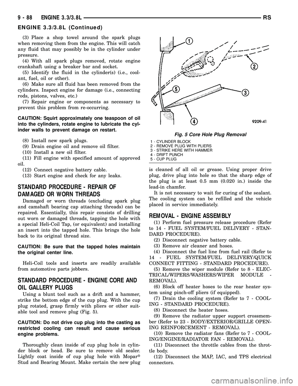
Using a blunt tool such as a drift and a hammer,
strike the bottom edge of the cup plug. With the cup
plug rotated, grasp firmly with pliers or other suit-
able tool and remove plug (Fig. 5).
CAUTION: Do not drive cup plug into the casting as
restricted cooling can result and cause serious
engine problems.
Thoroughly clean inside of cup plug hole in cylin-
der block or head. Be sure to remove old sealer.
Lightly coat inside of cup plug hole with Mopart
Stud and Bearing Mount. Make certain the new plugis cleaned of all oil or grease. Using proper drive
plug, drive plug into hole so that the sharp edge of
the plug is at least 0.5 mm (0.020 in.) inside the
lead-in chamfer.
It is not necessary to wait for curing of the sealant.
The cooling system can be refilled and the vehicle
placed in service immediately.
REMOVAL - ENGINE ASSEMBLY
(1) Perform fuel pressure release procedure (Refer
to 14 - FUEL SYSTEM/FUEL DELIVERY - STAN-
DARD PROCEDURE).
(2) Disconnect negative battery cable.
(3) Remove air cleaner and hoses.
(4) Disconnect the fuel line from fuel rail (Refer to
14 - FUEL SYSTEM/FUEL DELIVERY/QUICK
CONNECT FITTING - STANDARD PROCEDURE).
(5) Remove the wiper module (Refer to 8 - ELEC-
TRICAL/WIPERS/WASHERS/WIPER MODULE -
REMOVAL).
(6) Block off heater hoses to the rear heater sys-
tem using pinch-off pliers (if equipped).
(7) Drain the cooling system (Refer to 7 - COOL-
ING - STANDARD PROCEDURE).
(8) Disconnect the heater hoses.
(9) Remove the radiator upper support crossmem-
ber (Refer to 23 - BODY/EXTERIOR/GRILLE OPEN-
ING REINFORCEMENT - REMOVAL).
(10) Remove the radiator fans (Refer to 7 - COOL-
ING/ENGINE/RADIATOR FAN - REMOVAL).
(11) Disconnect the throttle cables from the throt-
tle body.
(12) Disconnect the MAP, IAC, and TPS electrical
connectors.
Fig. 5 Core Hole Plug Removal
1 - CYLINDER BLOCK
2 - REMOVE PLUG WITH PLIERS
3 - STRIKE HERE WITH HAMMER
4 - DRIFT PUNCH
5 - CUP PLUG
9 - 88 ENGINE 3.3/3.8LRS
ENGINE 3.3/3.8L (Continued)
Page 1270 of 2339
(49) Install the radiator upper support crossmem-
ber (Refer to 23 - BODY/EXTERIOR/GRILLE OPEN-
ING REINFORCEMENT - INSTALLATION).
(50) Install the wiper module (Refer to 8 - ELEC-
TRICAL/WIPERS/WASHERS/WIPER MODULE -
INSTALLATION).
(51) Connect the fuel line to fuel rail (Refer to 14 -
FUEL SYSTEM/FUEL DELIVERY/FUEL LINES -
STANDARD PROCEDURE).
(52) Install the air cleaner and hoses.
(53) Install new oil filter. Fill engine crankcase
with proper oil to correct level.
(54) Connect negative cable to battery.
(55) Fill the cooling system (Refer to 7 - COOLING
- STANDARD PROCEDURE).
(56) Start engine and run until operating temper-
ature is reached.
(57) Adjust transmission linkage, if necessary.
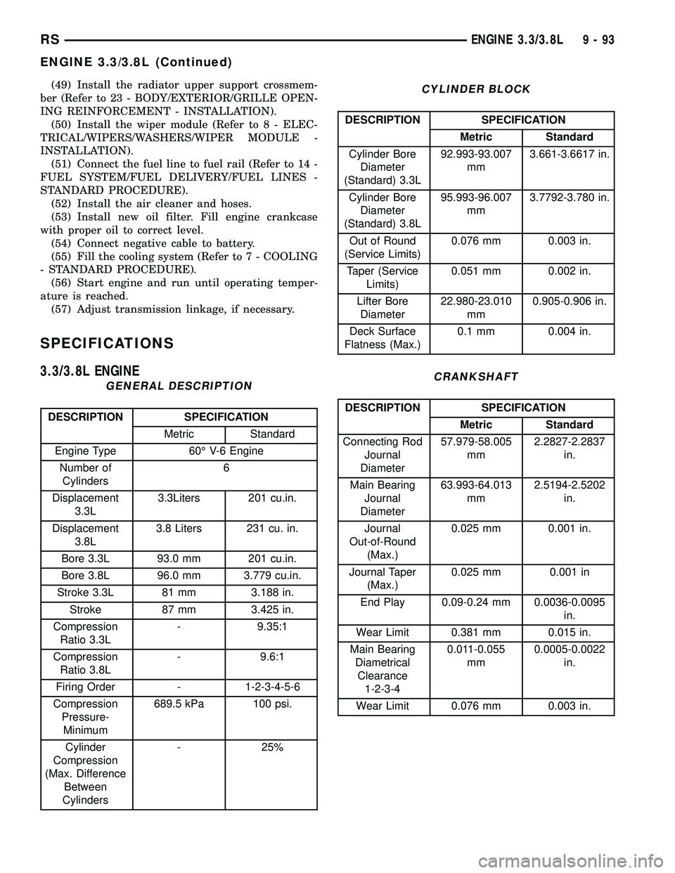
SPECIFICATIONS
3.3/3.8L ENGINE
GENERAL DESCRIPTION
DESCRIPTION SPECIFICATION
Metric Standard
Engine Type 60É V-6 Engine
Number of
Cylinders6
Displacement
3.3L3.3Liters 201 cu.in.
Displacement
3.8L3.8 Liters 231 cu. in.
Bore 3.3L 93.0 mm 201 cu.in.
Bore 3.8L 96.0 mm 3.779 cu.in.
Stroke 3.3L 81 mm 3.188 in.
Stroke 87 mm 3.425 in.
Compression
Ratio 3.3L- 9.35:1
Compression
Ratio 3.8L- 9.6:1
Firing Order - 1-2-3-4-5-6
Compression
Pressure-
Minimum689.5 kPa 100 psi.
Cylinder
Compression
(Max. Difference
Between
Cylinders- 25%
CYLINDER BLOCK
DESCRIPTION SPECIFICATION
Metric Standard
Cylinder Bore
Diameter
(Standard) 3.3L92.993-93.007
mm3.661-3.6617 in.
Cylinder Bore
Diameter
(Standard) 3.8L95.993-96.007
mm3.7792-3.780 in.
Out of Round
(Service Limits)0.076 mm 0.003 in.
Taper (Service
Limits)0.051 mm 0.002 in.
Lifter Bore
Diameter22.980-23.010
mm0.905-0.906 in.
Deck Surface
Flatness (Max.)0.1 mm 0.004 in.
CRANKSHAFT
DESCRIPTION SPECIFICATION
Metric Standard
Connecting Rod
Journal
Diameter57.979-58.005
mm2.2827-2.2837
in.
Main Bearing
Journal
Diameter63.993-64.013
mm2.5194-2.5202
in.
Journal
Out-of-Round
(Max.)0.025 mm 0.001 in.
Journal Taper
(Max.)0.025 mm 0.001 in
End Play 0.09-0.24 mm 0.0036-0.0095
in.
Wear Limit 0.381 mm 0.015 in.
Main Bearing
Diametrical
Clearance
1-2-3-40.011-0.055
mm0.0005-0.0022
in.
Wear Limit 0.076 mm 0.003 in.
RSENGINE 3.3/3.8L9-93
ENGINE 3.3/3.8L (Continued)
Page 1316 of 2339

OIL
STANDARD PROCEDURE
STANDARD PROCEDURE - ENGINE OIL AND
FILTER CHANGE
Change engine oil at mileage and time intervals
described in the Maintenance Schedule. (Refer to
LUBRICATION & MAINTENANCE/MAINTE-
NANCE SCHEDULES - DESCRIPTION)
WARNING: NEW OR USED ENGINE OIL CAN BE
IRRITATING TO THE SKIN. AVOID PROLONGED OR
REPEATED SKIN CONTACT WITH ENGINE OIL.
CONTAMINANTS IN USED ENGINE OIL, CAUSED BY
INTERNAL COMBUSTION, CAN BE HAZARDOUS TO
YOUR HEALTH. THOROUGHLY WASH EXPOSED
SKIN WITH SOAP AND WATER. DO NOT WASH
SKIN WITH GASOLINE, DIESEL FUEL, THINNER, OR
SOLVENTS, HEALTH PROBLEMS CAN RESULT. DO
NOT POLLUTE, DISPOSE OF USED ENGINE OIL
PROPERLY. CONTACT YOUR DEALER OR GOVERN-
MENT AGENCY FOR LOCATION OF COLLECTION
CENTER IN YOUR AREA.Run engine until achieving normal operating tem-
perature.
(1) Position the vehicle on a level surface and turn
engine off.
(2) Open hood, remove oil fill cap (Fig. 97).
(3) Hoist and support vehicle on safety stands.
Refer to Hoisting and Jacking Recommendations.
(Refer to LUBRICATION & MAINTENANCE/HOIST-
ING - STANDARD PROCEDURE)
(4) Place a suitable drain pan under crankcase
drain (Fig. 96).
(5) Remove drain plug from crankcase (Fig. 96)
and allow oil to drain into pan. Inspect drain plug
threads for stretching or other damage. Replace
drain plug and gasket if damaged.
(6) Remove oil filter. (Refer to 9 - ENGINE/LUBRI-
CATION/OIL FILTER - REMOVAL)
(7) Install and tighten drain plug in crankcase.
(8) Install new oil filter. (Refer to 9 - ENGINE/LU-
BRICATION/OIL FILTER - INSTALLATION)
(9) Lower vehicle and fill crankcase with specified
type and amount of engine oil. (Refer to LUBRICA-
TION & MAINTENANCE/FLUID TYPES -
DESCRIPTION)
(10) Install oil fill cap.
Fig. 95 Engine Oiling System
1 - OIL SUPPLY FOR BALL SOCKET THROUGH PUSH ROD 7 - OUTER ROTOR
2 - OIL SUPPLY PASSAGE FROM SHAFT TO ROCKER ARM 8 - INNER ROTOR
3 - ROCKER SHAFT 9 - RELIEF VALVE
4 - OIL FLOWS TO ONLY ONE PEDASTAL ON EACH HEAD; THIRD
FROM REAR ON RIGHT HEAD, THIRD FROM FRONT ON LEFT
HEAD10 - OIL PAN
5 - ROCKER SHAFT TOWER 11 - OIL SCREEN
6 - CRANKSHAFT 12 - OIL PUMP CASE
RSENGINE 3.3/3.8L9 - 139
LUBRICATION (Continued)
Page 1366 of 2339
FUEL SYSTEM
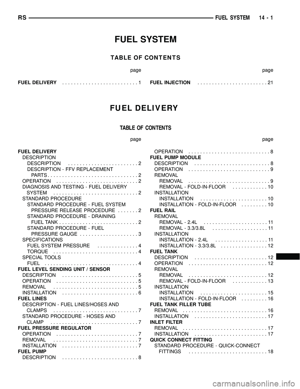
TABLE OF CONTENTS
page page
FUEL DELIVERY..........................1FUEL INJECTION........................21
FUEL DELIVERY
TABLE OF CONTENTS
page page
FUEL DELIVERY
DESCRIPTION
DESCRIPTION........................2
DESCRIPTION - FFV REPLACEMENT
PARTS...............................2
OPERATION............................2
DIAGNOSIS AND TESTING - FUEL DELIVERY
SYSTEM.............................2
STANDARD PROCEDURE
STANDARD PROCEDURE - FUEL SYSTEM
PRESSURE RELEASE PROCEDURE.......2
STANDARD PROCEDURE - DRAINING
FUEL TANK...........................2
STANDARD PROCEDURE - FUEL
PRESSURE GAUGE....................3
SPECIFICATIONS
FUEL SYSTEM PRESSURE..............4
TORQUE.............................4
SPECIAL TOOLS
FUEL................................4
FUEL LEVEL SENDING UNIT / SENSOR
DESCRIPTION..........................5
OPERATION............................5
REMOVAL.............................5
INSTALLATION..........................6
FUEL LINES
DESCRIPTION - FUEL LINES/HOSES AND
CLAMPS.............................7
STANDARD PROCEDURE - HOSES AND
CLAMP..............................7
FUEL PRESSURE REGULATOR
OPERATION............................7
REMOVAL.............................7
INSTALLATION..........................7
FUEL PUMP
DESCRIPTION..........................8OPERATION............................8
FUEL PUMP MODULE
DESCRIPTION..........................8
OPERATION............................9
REMOVAL
REMOVAL............................9
REMOVAL - FOLD-IN-FLOOR............10
INSTALLATION
INSTALLATION.......................10
INSTALLATION - FOLD-IN-FLOOR.........10
FUEL RAIL
REMOVAL
REMOVAL - 2.4L......................11
REMOVAL - 3.3/3.8L...................11
INSTALLATION
INSTALLATION - 2.4L..................11
INSTALLATION - 3.3/3.8L................12
FUEL TANK
DESCRIPTION.........................12
OPERATION...........................12
REMOVAL
REMOVAL...........................12
REMOVAL - FOLD-IN-FLOOR............13
INSTALLATION
INSTALLATION.......................15
INSTALLATION - FOLD-IN-FLOOR.........16
FUEL TANK FILLER TUBE
REMOVAL.............................16
INSTALLATION.........................17
INLET FILTER
REMOVAL.............................17
INSTALLATION.........................17
QUICK CONNECT FITTING
STANDARD PROCEDURE - QUICK-CONNECT
FITTINGS...........................18
RSFUEL SYSTEM14-1
Page 1367 of 2339
FUEL DELIVERY
DESCRIPTION
DESCRIPTION
The front wheel drive car uses a plastic fuel tank
located rear center of the vehicle.
The Fuel Delivery System consists of: the following
items:
²Electric fuel pump module
²Fuel filter
²Tubes/lines/hoses
²Fuel injectors
The in-tank fuel pump module contains the fuel
pump. The pump is serviced as part of the fuel pump
module. Refer to Fuel Pump Module.
The fuel filter is replaceable only as part of the
fuel pump module.
DESCRIPTION - FFV REPLACEMENT PARTS
Many components in a Flexible Fuel Vehicle (FFV)
are designed to be compatible with ethanol. Always
be sure that the vehicle is serviced with correct etha-
nol compatible parts.
CAUTION: Replacing fuel system components with
non-ethanol compatible components can damage
your vehicle and may void the warranty.
OPERATION
The fuel system provides fuel pressure by an
in-tank pump module. The Powertrain Control Mod-
ule (PCM) controls the operation of the fuel system
by providing battery voltage to the fuel pump
through the fuel pump relay. The PCM requires only
three inputs and a good ground to operate the fuel
pump relay. The three inputs are:
²Ignition voltage
²Crankshaft Position (CKP) sensor
²Camshaft Position (CMP) sensor
DIAGNOSIS AND TESTING - FUEL DELIVERY
SYSTEM
(Refer to Appropriate Diagnostic Information)
STANDARD PROCEDURE
STANDARD PROCEDURE - FUEL SYSTEM
PRESSURE RELEASE PROCEDURE
(1) Remove Fuel Pump relay from Power Distribu-
tion Center (PDC). For location of relay, refer to label
on underside of PDC cover.
(2) Start and run engine until it stalls.(3) Attempt restarting engine until it will no
longer run.
(4) Turn ignition key to OFF position.
(5) Return fuel pump relay to PDC.
(6) One or more Diagnostic Trouble Codes (DTC's)
may have been stored in PCM memory due to fuel
pump relay removal. The DRB IIItscan tool must be
used to erase a DTC.
STANDARD PROCEDURE - DRAINING FUEL
TANK
Two different procedures may be used to drain fuel
tank (lowering tank or using DRBIIItscan tool).
The quickest draining procedure involves lowering
the fuel tank.
WARNING: RELEASE FUEL SYSTEM PRESSURE
BEFORE SERVICING FUEL SYSTEM COMPONENTS.
SERVICE VEHICLES IN WELL VENTILATED AREAS
AND AVOID IGNITION SOURCES. NEVER SMOKE
WHILE SERVICING THE VEHICLE. THIS MAY
RESULT IN PERSONAL INJURY OR DEATH.
As an alternative procedure, the electric fuel pump
may be activated allowing tank to be drained at fuel
rail connection. Refer to DRBIIItscan tool for fuel
pump activation procedures. Before disconnecting
fuel line at fuel rail, release fuel pressure. Refer to
the Fuel System Pressure Release Procedure in this
group for procedures. Disconnect the fuel line at the
fuel rail and remove the plastic retainer from the
fuel rail. Take plastic retainer and install it back into
the fuel line from body. Check the O-ring and make
sure that it is in place and not damaged. Attach end
of special test hose tool number 6539 at fuel line con-
nection from the body line. Position opposite end of
this hose tool to an approved gasoline draining sta-
tion. Activate fuel pump and drain tank until empty.
When done remove the special test hose tool number
6539 from the body line. Remove the plastic retainer
from the special test hose tool number 6539 and rein-
stall it into the fuel line from the body. Check the
O-ring and make sure that it is in place and not
damaged. Install the fuel line to the fuel rail.
If electric fuel pump is not operating, tank must be
lowered for fuel draining. Refer to following proce-
dures.
(1) Remove fuel filler cap.
(2) Perform the Fuel System Pressure Release pro-
cedure.
(3) Disconnect negative cable from battery.
(4) Raise vehicle and support.
(5) Certain models are equipped with a separate
grounding wire (strap) connecting the fuel fill tube
assembly to the body. Disconnect wire by removing
screw.
14 - 2 FUEL DELIVERYRS
Page 1369 of 2339
SPECIFICATIONS
FUEL SYSTEM PRESSURE
400 kpa 34 kpa (58 psi 5 psi)
TORQUE
DESCRIPTION N´m Ft. Lbs. In. Lbs.
Fuel Filler Neck Clamp 3.3 30
Fuel Rail 2.4L 22 195
Fuel Rail 3.3/3.8L 11.8 105
Fuel Tank Strap 54 40
Fuel Tank T Strap 28.2 250
Fuel Filter Bolt 4.5 40
SPECIAL TOOLS
FUEL
Pressure Gauge Assembly C±4799±B
Fuel Pressure Test Adapter 6539
Spanner Wrench 6856
LOCKRING REMOVER/INSTALLER #9340
Fuel Line Adapter 1/4
14 - 4 FUEL DELIVERYRS
FUEL DELIVERY (Continued)
Page 1374 of 2339
²Fuel supply line connection
The inlet strainer, fuel pressure regulator
and fuel level sensor are the only serviceable
items. If the fuel pump or electrical wiring har-
ness requires service, replace the fuel pump
module.
The electric fuel pump is located in and is part of
the fuel pump module. It is a positive displacement,
gerotor type, immersible pump with a permanent
magnet electric motor.
OPERATION
The pump draws fuel through a strainer and
pushes it through the motor to the outlet. The pump
contains one check valve. The check valve, in the
pump outlet, maintains pump pressure during engine
off conditions. The fuel pump relay provides voltage
to the fuel pump.
The fuel pump has a maximum deadheaded pres-
sure output of approximately 880 kPa (130 psi). The
regulator adjusts fuel system pressure to approxi-
mately 400 34 kPa (58 5 psi).
FUEL PUMP ELECTRICAL CONTROL
Voltage to operate the electric pump is supplied
through the fuel pump relay. For an electrical opera-
tional description of the fuel pump refer to fuel Pump
RelayÐPCM Output.
ELECTRICAL PUMP REPLACEMENT
The electric fuel pump is not serviceable. If the
fuel pump or electrical wiring harness needs replace-
ment, the complete fuel pump module must be
replaced. Perform the Fuel System Pressure Release
procedure before servicing the fuel pump.
REMOVAL
REMOVAL
WARNING: RELEASE FUEL SYSTEM PRESSURE
BEFORE SERVICING FUEL SYSTEM COMPONENTS.
SERVICE VEHICLES IN WELL VENTILATED AREAS
AND AVOID IGNITION SOURCES. NEVER SMOKE
WHILE SERVICING THE VEHICLE.
(1) Remove fuel filler cap and perform Fuel Sys-
tem Pressure Release procedure.
(2) Disconnect negative cable from auxiliary
jumper terminal.
(3) Drain fuel tank, refer to the Fuel Tank proce-
dure in the Fuel Delivery section.
(4) Remove fuel tank, refer to the Fuel Tank
removal section.
(5) Clean top of tank to remove loose dirt and
debris.
(6) Using a brass punch and hammer remove lock-
nut to release pump module (Fig. 13).
Fig. 12 FUEL PUMP MODULE Ð NON FOLD-IN-
FLOOR
1 - INLET STRAINER
2 - FUEL RESERVOIR
3 - FUEL PRESSURE REGULATOR
4 - FUEL LEVEL SENSOR
5 - FILTER
6 - GROUND STRAPS
Fig. 13 FUEL PUMP MODULE LOCKING RING
RSFUEL DELIVERY14-9
FUEL PUMP MODULE (Continued)